Note : Les descriptions sont présentées dans la langue officielle dans laquelle elles ont été soumises.
CA 02587999 2007-05-08
US20050463
DISHWASHER WITH UTENSIL RACK AND SLIDES THEREFOR
CROSS-REFERENCE TO RELATED APPLICATION
This application is a continuation-in-part of U.S. Patent Application No.
11/092,453 filed March 29, 2005.
BACKGROUND OF THE INVENTION
Field of the Invention
The invention relates generally to a household dishwasher with a utensil rack
and
a slide for supporting the utensil rack.
Description of the Related Art
Automatic dishwashers are well known, especially those for use in household
environments. A typical automatic dishwasher comprises a cabinet that defines
a
washing chamber, which is accessible through a moveable door. Typically, an
upper rack
and a lower rack for holding utensils to be cleaned are provided within the
washing
chamber. Both the upper and lower racks are slidably mounted within the
washing
chamber in such a manner that at least a major portion of the racks can be
slid
substantially beyond the washing chamber to ease the loading of the racks.
A problem associated with conventional dishwasher racks relates to the slides
that
mount the racks to the side walls of the dishwasher cabinet. Usually, the
racks include
wheels or similar devices mounted to the sides thereof, and the wheels ride
within a slide
movably mounted to the cabinet. To remove the rack from the dishwasher, the
user pulls
the rack out of the wash chamber by sliding the wheel toward the end of the
slide and,
once the rack reaches the end of the slide, removes the wheels from the slide,
usually by
slightly lifting the rack to lift the wheel over a detent in the slide while
continuing to pull.
However, with such a configuration, it is easy for the user to accidentally
pull the wheel
over the detent while pulling the rack out of the wash chamber in a normal
fashion and
-1-
CA 02587999 2007-05-08
US20050463
thereby unintentionally remove the rack from the slide. It is therefore
desirable to have
an automatic dishwasher with a slide that prevents undesired removal of the
rack.
SUMMARY OF THE INVENTION
An automatic dishwasher according to another embodiment of the invention
comprises an open-faced cabinet comprising opposing side walls and defining a
wash
chamber; a door movably mounted to the cabinet for selectively closing the
wash
chamber; a utensil rack comprising opposing sides; at least one track defining
an
elongated raceway and comprising a stop terminating at a forward end of the
raceway and
an access opening to the raceway; and a wheel assembly comprising at least one
wheel
slidably received within the raceway and sized for insertion and removal
through the
access opening. One of the track and wheel assembly is mounted to one of the
cabinet
and utensil rack and the other of the track and wheel assembly is mounted to
the other of
the cabinet and utensil rack to slidably mount the utensil rack to the
cabinet, and the
wheel moves along the raceway to the access opening for removal through the
access
opening. A closure can be provided for closing the access opening.
BRIEF DESCRIPTION OF THE DRAWINGS
In the drawings:
Fig. 1 is a perspective view of a household dishwasher according to one
embodiment of the invention comprising two conventional utensil racks and a
third
utensil rack positioned within a wash chamber of the dishwasher, wherein the
third
utensil rack is mounted to the dishwasher by a pair of slides and comprises a
frame that
supports a pair of basket elements, which are shown in an upper position on
the frame.
Fig. 2 is a perspective view of the dishwasher of Fig. 1 with the third
utensil rack
according to one embodiment of the invention slid exteriorly from the wash
chamber.
Fig. 3 is an exploded view of the slides and the third utensil rack of Fig. 2
according to one embodiment of the invention.
-2-
CA 02587999 2007-05-08
US20050463
Fig. 4 is a perspective view of one of the basket elements of Fig. 2 according
to
one embodiment of the invention.
Fig. 5 is a front view of the dishwasher of Fig. 1, with a traditional upper
rack
shown in phantom for clarity, and the third utensil rack according to one
embodiment of
the invention shown in an upper position.
Fig. 6 is a perspective view of the dishwasher similar to Fig. 2, except that
the
basket elements are shown in a lower position on the frame.
Fig. 7 is a front view of the dishwasher similar to Fig. 5, except that the
basket
elements are in the lower position on the frame.
Fig. 8 is an enlarged exploded view of a track and closure of the slides of
Fig. 3
according to one embodiment of the invention.
Fig. 9A is enlarged view of the region labeled 9A in Fig. 6 with the closure
on the
slide shown in a closed position.
Fig. 9B is enlarged view similar to Fig. 9A, except that the closure on the
slide is
shown in an opened position and a wheel on the third rack is aligned with an
access
opening in the top of the slide.
Fig. 10 is an enlarged perspective view of a wheel support from the third
utensil
rack of Fig. 3 according to one embodiment of the invention.
Fig. 11 is an enlarged perspective view similar to Fig. 9B with the wheel
being
removed from the slide through the access opening according to one embodiment
of the
invention.
Fig. 12 is an enlarged perspective view of an alternative slide according to
one
embodiment of the invention having an access opening at the end of the slide.
Fig. 13 is a perspective view of a utensil rack with an alternative embodiment
pair
of slides according to one embodiment of the invention.
Fig. 14 is an exploded view of the slide and a wheel support of Fig. 13
according
to one embodiment of the invention.
Fig. 15 is a perspective view of the slide of Fig. 13, wherein the slide is
shown in
an initial position.
-3-
CA 02587999 2007-05-08
US20050463
Fig. 16 is an exploded view of the slide of Fig. 14.
Figs. 17-19 are perspective views similar to Fig. 15 showing an exemplary
operation of the slide as it moves from the initial position of Fig. 15.
Fig. 20 is an enlarged view of the region labeled XX of Fig. 19 showing a
closure
on the slide in a closed position.
Fig. 21 is a perspective view similar to Fig. 20 showing the closure on the
slide in
an opened position.
Fig. 22 is a perspective view similar to Fig. 20 of an alternative embodiment
slide.
DESCRIPTION OF EMBODIMENTS OF THE INVENTION
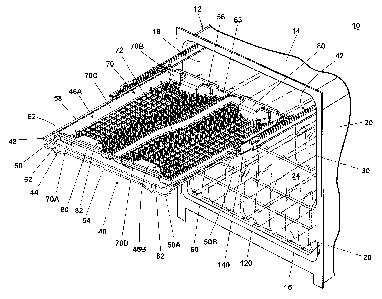
Referring now to the figures, Fig. 1 shows a household dishwasher 10 according
to one embodiment of the invention comprising a cabinet 12 having spaced upper
and
lower walls 14, 16 joined by opposing side walls 18, 20 and a rear wal122 to
form an
open-faced wash chamber 24. A door 26 movably mounted to the cabinet 12 is
movable
between an open position, as shown in Fig. 1, wherein the user can access the
wash
chamber 24, and a closed position, wherein the door 26 closes the open face of
the wash
chamber 24 in a conventional fashion. The dishwasher 10 further comprises a
lower, first
utensil rack 28 and a higher, second utensil rack 30 slidably mounted the side
walls 18,
of the cabinet 12. The first and second utensil racks 28, 30 are preferably
conventional
20 utensil racks commonly utilized in present day household dishwashers for
holding various
utensils, such as plates, bowls, other tableware, and beverage containers.
Usually, the
first utensil rack 28 is adapted to hold plates, bowls, and large items, such
as pots and
pans, and the second utensil rack 30 is spaced a sufficient distance above the
first utensil
rack 28 to accommodate the items in the first utensil rack 30. The second
utensil rack 30
commonly holds beverage containers, such as glasses and cups, and other small
items.
However, the first and second utensil racks 28, 30 can be arranged in the
dishwasher 10
in any suitable fashion and can hold any utensils that can be washed in the
dishwasher 10.
During operation of a wash cycle of the dishwasher 10, the door 26 is in the
closed
position, and the first and second utensil racks 28, 30 are disposed within
the wash
-4-
CA 02587999 2007-05-08
US20050463
chamber 24 and exposed to washing fluid, such as water, and wash aids, such as
detergents and rinse aids. When dishwasher 10 is not operating, the user can
move the
door 26 to the open position and slide the first and second utensil racks 28,
30 from the
wash chamber to empty or fill the first and the second utensil racks 28, 30.
As shown in Fig. 2, according to one embodiment of the invention, the
dishwasher
can further comprise a third utensil rack 40 slidably mounted to the cabinet
12 by a
pair of slides 42. The third utensil rack 40 can be positioned above the
second utensil
rack 30 and near the upper wall 14 within the wash chamber 24 and can move
relative to
the wash chamber 24 in the same manner as described above for the first and
second
10 utensil racks 28, 30. The third utensil rack 40 comprises a frame 44 that
supports a pair
of removable basket elements 46A, 46B, which can hold several types of
utensils having
various sizes and shapes.
Referring now to Fig. 3, the frame 44 comprises an upper U-shaped wire 48 and
a
generally rectangular lower peripheral wire 50 joined by a plurality of spaced
and
generally vertical connecting wires 52. The peripheral wires 48, 50 form
spaced front and
rear ends 54, 56 connected by opposing sides 58, 60. The U-shaped wire 48 is
oriented
such that it opens at the rear end 56, and the lower peripheral wire 50 is
formed by a pair
of opposed, U-shaped front and rear lower peripheral wires 50A, 50B that join
at the
opposing sides 58, 60. The frame 44 further comprises a front upper support
rai162 and a
rear upper support rai163 that extend between and above the opposing sides 58,
60 of the
upper peripheral wire 48 and are parallel to and spaced from the front end 54
and the rear
end 56, respectively. Additionally, the frame 44 includes a first pair of
opposing lower
support rails 64 and a second pair of opposing lower support rails 66 on the
opposing
sides 58, 60 of the frame 44. The first pair of lower support rails 64 is
integral with the
front upper support rai162, and, similarly, the second pair of lower support
rails 66 is
integral with the rear upper support rai163. Each of the lower support rails
64, 66 is
elongated and generally U-shaped and depends from the upper peripheral wire 48
such
that it extends below the lower peripheral wire 50. Thus, the upper support
rails 62, 63
are vertically spaced from the lower support rails 64, 66. The upper and lower
peripheral
-5-
CA 02587999 2007-05-08
US20050463
wires 48, 50, the upper support rails 62, 63, and the lower support rails 64,
66 are
preferably metal wires coated with polymeric materials that can withstand the
environment of the wash chamber 24 and protect the metal wires from corrosion.
Alternatively, the upper and lower peripheral wires 48, 50, the upper support
rails 62, 63,
and the lower support rails 64, 66 can be composed entirely of polymeric
materials.
Refemng now to Fig. 4, according to one embodiment of the invention, the
basket
elements 46A, 46B, which rest on the frame 44, each comprise an upstanding
peripheral
wall 70 and a grid formed by a plurality of intersecting ribs 72 that form a
bottom wall
surrounded by the peripheral wall 70. The intersecting ribs 72 are spaced from
one
another a distance suitable for holding utensils such as silverware, spatulas,
and the like.
Further, the bottom wall optionally includes at least one small item support
area 68
comprising intersecting support ribs 86 that are spaced closer than the
intersecting ribs 72
to support small items, such as corn cob holders, that can potentially fall
between the
intersecting ribs 72. As shown in Fig. 4, the small item support areas 68 are
preferably
located in corners of basket elements 46A, 46B, but they can be located in any
suitable
region of the bottom wall.
The peripheral wall 70 comprises parallel and spaced first and second edges
70A,
70B joined by spaced third and fourth edges 70C, 70D. Each of the first and
second
edges 70A, 70B are substantially straight and can include a cany handle 80
formed
integrally therewith. Each of the handles can comprise a lateral hook or
flange 82 sized
to receive the upper and lower support rails 62, 63, 64, 66. The third edge
70C is
generally straight and perpendicular to the first and second edges 70A, 70B,
while the
fourth edge 70D can comprise an intermediate curve 74 to form a first basket
element
portion 76 and a second basket element portion 78 that is wider than the first
basket
element portion 76. As a result of this configuration, utensils of different
length can be
efficiently arranged within the basket elements 46A, 46B. As shown in Fig. 4,
relatively
short utensils A, such as standard forks and spoons, can be placed in the
first basket
element portion 76 in an orientation parallel to the first and second edges
70A, 70B,
while medium length utensils B, such as table knives, can fit in the second
basket element
-6-
CA 02587999 2007-05-08
US20050463
portion 78 also in an orientation generally parallel to the first and second
edges 70A, 70B.
Additionally, the basket elements 46A, 46B are sized so that relatively long
utensils C,
such as spatulas, mixing spoons, chef knives, and the like, can be arranged
across both
the first and second basket element portions 76, 78 in an orientation parallel
to the third
edge 70C and generally perpendicular to the relatively short utensils A and
the medium
length utensils B. As illustrated in Fig. 4, the relatively long utensils C
are longer than
the medium length utensils B, which are longer than the relatively short
utensils A.
However, the utensils can be placed in any suitable location of the basket
elements 46A,
46B. For example, the relatively short utensils A can be placed in the second
basket
element portion 78, if desired.
Each basket element 46A, 46B can further comprise a plurality of tines 88
projecting upward from the intersecting ribs 72 to support and separate
individual
utensils. The tines 88 can be arranged in groups so that the user can
efficiently position
utensils of different length in different areas of the basket elements 46A,
46B. A first tine
group 90 extends along the fourth edge 70D for holding utensils in an
orientation parallel
to the first and second edges 70A, 70B, and a second tine group 92 is disposed
along the
second edge 70B for holding utensils in an orientation parallel to the third
edge 70C.
Preferably, the tines 88 in the first tine group 90 are spaced to hold
relatively thin utensils,
such as table knives, spoons, and forks (i.e., the relatively short utensils A
and the
medium length utensils B), while the tines 88 in the second tine group 92 are
spaced
farther apart to accommodate wider utensils, such as spatulas (i.e., the
relatively long
utensils C). Further, the tines 88 are preferably arranged in pairs of tines
to form two
parallel rows 88A, 88B of tines 88. As a result of this configuration, the
utensils
positioned between the tines 88 are held by the tines 88 at two locations
along the length
thereof, and, therefore, the rows 88A, 88B of tines 88 prevent pivotal
movement of the
utensils and maintain the utensils in the orientation generally parallel to
the first and
second edges 70A, 70B or parallel to the third edge 70C. Additionally, the
second group
of tines 92 includes a third row 88C of tines 88 along the first edge 70A for
securing both
ends of the relatively long utensils C to prevent the pivotal movement
thereof.
-7-
CA 02587999 2007-05-08
US20050463
Referring back to Fig. 2, according to one embodiment of the invention, the
fourth
edges 70D of the basket elements 46A, 46B are complementary and matingly abut
one
another when the basket elements 46A, 46B are seated on the frame 44. As a
result, the
first edges 70A, the second edges 70B, and the third edges 70C of both of the
basket
elements 46A, 46B form a generally rectangular periphery with a minor
discontinuation at
the interface between the basket elements 46A, 46B. Further, because the
basket
elements 46A, 46B are complementary, the basket elements 46A, 46B mate to form
a
whole, generally rectangular basket. The whole basket is defined by the
rectangular
periphery and has a surface area slightly less than the area defined between
the front and
rear ends 54, 56 and the opposing sides 58, 60 of the frame 44. In particular,
the whole
basket corresponds to a single basket sized to span in one direction between
the upper
support rails 62, 63 and in the other direction a distance slightly less than
the distance
between the first and second pairs of opposing lower support rails 64, 66. In
the
illustrated embodiment, the first basket element portion 76 of the first
basket element
46A aligns with the second basket element portion 78 of the second basket
element 46B,
and the second basket element portion 78 of the first basket element 46A
aligns with the
first basket element portion 76 of the second basket element 46B to form the
whole
basket, which has a constant width equal to the sum of the individual widths
of the basket
element portions 76, 78. Preferably, the basket elements 46A, 46B are
identical in shape
and size so that each of the basket elements 46A, 46B accounts for about one
half of the
whole basket. Further, production costs are minimized when the basket elements
46A,
46B are identical because only a single mold design is required for all of the
basket
elements 46A, 46B.
The basket elements 46A, 46B are adjustably mounted to the frame 44 to
accommodate utensils held by the second utensil rack 30 and utensils held by
the basket
elements 46A, 46B and to efficiently utilize the limited space in the wash
chamber 24. In
particular, the basket elements 46A, 46B can be vertically adjustable on the
frame 44 and,
therefore, within the wash chamber 24. As shown in Figs. 2 and 5, according to
one
embodiment of the invention, the basket elements 46A, 46B can be mounted in an
upper
-8-
CA 02587999 2007-05-08
US20050463
position wherein the flanges 82 on the first and second edges 70A, 70B rest on
the upper
support rails 62, 63. As shown in Figs. 6 and 7, according to one embodiment
of the
invention, the basket elements 46A, 46B can be mounted in a lower position,
wherein the
flanges 82 on the first and second edges 70A, 70B rest on the first and second
pairs of
opposing lower support rails 64, 66. A comparison of Figs. 5 and 7 shows that
the basket
elements 46A, 46B are located higher in the wash chamber 24 when in the upper
position.
Further, the bottom walls formed by the intersecting ribs 72 of the basket
elements 46A,
46B are spaced from the second utensil rack 30 a greater distance when the
basket
elements 46A, 46B are in the upper position than when the basket elements 46A,
46B are
in the lower position, but clearance between the bottom walls and the upper
wall 14 of the
cabinet 12 is greater when the basket elements 46A, 46B are in the lower
position than
when in the upper position. Mounting the basket elements 46A, 46B in the upper
and the
lower positions is, therefore, a compromise between spacing between the second
utensil
rack 30 and the third utensil rack 40 and clearance between the third utensil
rack 40 and
the upper wall 14 of the cabinet 12. Additionally, the basket elements 46A,
46B in the
upper position are oriented generally orthogonal to the basket elements 46A,
46B in the
lower position because the portions of the frame 44 that support the basket
elements 46A,
46B in these two positions are oriented orthogonal to one another. Such an
arrangement
facilitates mounting the basket elements 46A, 46B to the frame 44 since the
upper
support rails 62, 63 do not interfere with the basket elements 46A, 46B when
mounting
them on the first and second pairs of opposing lower support rails 64, 66 and
vice-versa.
Referring particularly to Fig. 8 and generally to Fig. 3, the slides 42 that
slidably
mount the third utensil rack 40 to the cabinet 12 each comprise a track 100
having a
generally vertical middle wall 102 with an aperture 103 near a front end
thereof and pairs
of upper and lower L-shaped flanges 104, 106 extending along the middle wall
102 to
define an inner raceway 110 on an interior side (i.e., the side closer to the
third utensil
rack 40) of the middle wall 102 and an outer raceway 110 on an outer side
(i.e., the side
farther from the third utensil rack 40) of the middle wall 102. The raceways
110, 112
terminate at a pair of stops in the form of front flanges 108 at the front end
of the track
-9-
CA 02587999 2007-05-08
US20050463
100. The upper flange 104 that partially defines the inner raceway 110 is
spaced from the
front flange 108 on the interior side of the middle wall 102 to form an access
opening 114
therebetween. A closure 120 pivotally mounted to the upper and lower flanges
104, 106
of the track 100 selectively blocks the access opening 114. The closure 120
comprises
parallel upper and lower walls 122, 124 joined by a side wall 126 and a front
wall 128
orthogonal to the side wall 126. The side wall 126 and the front wall 128 form
a grip 130
sized to be grasped between a user's fingers for pivotally moving the closure
120.
Additionally, the closure 120 includes a detent 132 that extends from the side
wall 126
and is sized to mate with the aperture 103. The closure 120 is movable between
a closed
position, as shown in Fig. 9A, wherein the upper wall 122 blocks the access
opening 114,
and an opened position, as illustrated in Fig. 9B, wherein the closure 120 is
pivoted away
from the track 100 so that the upper wall 122 is spaced from the access
opening 114.
Referring particularly to Fig. 10 and generally to Fig. 3, a wheel support 140
couples each opposing side 58, 60 of the third utensil rack 40 to its
corresponding slide
42. Each wheel support 140 is an elongated, generally rectangular member with
front and
rear wheels 142, 144 rotatably mounted to an outer side thereof. The wheels
142, 144 are
sized for receipt within the access opening 114 and the inner raceway 110. The
wheel
support 140 further includes a pair of parallel grooves 146 on an interior
side thereof for
receiving the upper and lower peripheral wires 48, 50 of the frame 44. Snap
clamps 150
adjacent the grooves 146 are sized to securely receive at least one of the
upper and lower
peripheral wires 48, 50 to prevent lateral translation of the wheel support
140 relative to
the frame 44. Additionally, the interior side of the wheel support 140
includes sets of
vertically aligned U-shaped projections 148 between the grooves 146 sized to
receive
brackets 152 for sandwiching the frame 44 between the wheel support 140 and
the
brackets 152 to thereby mount the wheel support 140 to the frame 44. The wheel
support
140 also comprises an upwardly and outwardly extending overhang 154 to
facilitate
mounting the wheel support 140 to the track 100.
An exemplary description of the assembly and operation of the third utensil
rack
40 and the slides 42 follows. It will be apparent to one of ordinary skill
that the assembly
-10-
CA 02587999 2007-05-08
US20050463
and operation can proceed in any logical order and is not limited to the
sequence
presented below. The following description is for illustrative purposes only
and is not
intended to limit the invention in any way.
Each of the slides 42 is mounted to the dishwasher 10 by attaching the track
100
to a conventional slide mount (not shown) on the corresponding opposing side
wall 18,
20. The slide mount can be any suitable type of device that couples the track
100 to the
corresponding opposing side wall 18, 20. For example, the slide mount can
comprise one
or more wheels mounted to the side walls 18, 20. Typically, the track 100
receives the
slide mount within the outer raceway 112 so that the track 100 can slide
relative to the
cabinet 12. Next, the wheel supports 140 are mounted to the opposing sides 58,
60 of the
frame 44 by aligning the upper and lower peripheral wires 48, 50 with the
grooves 146,
snapping the lower peripheral wire 50 into the snap clamps 150, and inserting
the
brackets 152 into the projections 148 to clamp the upper and lower peripheral
wires 48,
50 between the wheel support 140 and the brackets 150. After the wheel
supports 140 are
secured to the frame 44, the user pivots the closures 120 on the slides 42 to
the opened
position so that the rear wheels 144 can be inserted into the inner raceways
110 through
the access openings 114. The user then pushes the frame 44 towards the wash
chamber
24 so that the rear wheels 144 travel along the inner raceway 110 until the
front wheels
142 are aligned with the access openings 114, as shown in Fig. 11. After the
user inserts
the front wheels 142 into the inner raceway 110 through the access openings
114, the user
pivots the closures 120 toward the track 100 to the closed position, wherein
the detents
132 mate with the apertures 103, and the upper walls 122 block the access
openings 114
to prevent inadvertent removal of the front wheels 142 from the inner raceways
110, as
shown in Fig. 9A. In this position, the overhangs 154 of the wheel supports
140 rest on
the upper flanges 104 of the track 100 to help support the frame 44 on the
slides 42.
When the slides 42 are mounted to the cabinet 12 and the frame 44 is mounted
to the
slides 42, the third utensil rack 40 is thereby mounted to the dishwasher 10
and can slide
relative to the wash chamber 24.
-11-
CA 02587999 2007-05-08
US20050463
The user can mount the basket elements 46A, 46B to the frame 44 in either the
upper position or the lower position depending on the desired configuration of
the utensil
racks 28, 30, 40 in the wash chamber 24, the sizes of the utensils in the
second utensil
rack 30, and the sizes of the utensils to be held in the third utensil rack
40. To maximize
the space between the second utensil rack 30 and the basket elements 46A, 46B,
the
basket elements 46A, 46B are placed adjacent one another in the upper
position, as shown
in Figs. 2 and 5, with the flanges 82 on the upper support rails 62, 63.
Further, the basket
elements 46A, 46B are positioned with their complementary, fourth edges 70D in
abutting contact to form the whole basket. However, if the user desires to
maximize the
clearance between the basket elements 46A, 46B and the upper wall 14 of the
cabinet 12
to fit larger utensils in the third utensil rack 40, the basket elements 46A,
46B are rotated
90-degrees and placed adjacent one another in the lower position, as
illustrated in Figs. 6
and 7, with the flanges 82 on the first and second opposing pairs of lower
support rails
64, 66. As in the upper position, the basket elements 46A, 46B are positioned
with their
complementary, fourth edges 70D in abutting contact to form the whole basket.
With the basket elements 46A, 46B in either the upper position or the lower
position, the user can fill the basket elements 46A, 46B with various shapes
and sizes of
utensils, including the relatively short utensils A, the medium length
utensils B, and the
relatively long utensils C, as described above. The utensils can be arranged
in the basket
elements 46A, 46B in any suitable fashion to maximize the quantity of utensils
held by
the third utensil rack 40 without compromising the ability of the dishwasher
10 to clean
the utensils. Additionally, the user can place small items, such as corn cob
holders, in the
small item support areas 68. During operation of a wash cycle, the tines 88
surrounding
the small item support areas 68 help retain the small items in the small item
support areas
68.
After the wash cycle is complete, the user pulls the third utensil rack 40
from the
wash chamber to empty the basket elements 46A, 46B. The front stop flanges 108
limit
the forward movement of the frame 44 relative to the slides 42. Next, the user
removes
the utensils from the third utensil rack 40 in any suitable manner. For
example, the user
-12-
CA 02587999 2007-05-08
US20050463
can either manually remove each utensil from the basket elements 46A, 46B
while the
basket elements 46A, 46B are mounted to the frame 44, the user can remove at
least one
of the basket elements 46A, 46B with the utensils therein and empty the at
least one
basket element 46A, 46B at a location separate from the dishwasher 10, or the
user can
remove at least one of the basket elements 46A, 46B with the utensils therein
and use the
at least one basket element 46A, 46B for utensil storage, such as by placing
the at least
one basket element 46A, 46B in a drawer.
If the user desires to remove the entire frame 44 from the dishwasher, the
user
pivots the closures 120 away from the tracks 100 to the opened position, as
shown in Fig.
9B, to unblock the access openings 114. The closures 120 in the illustrated
embodiment
advantageously remain mounted to the tracks 100 during movement between the
closed
and opened positions and while in the opened position. Next, the user aligns
the front
wheels 142 with the access openings 114 and lifts the frame 44, such as by
pivoting the
frame 44, to thereby lift the front wheels 142 through the access openings
114, as
illustrated in Fig. 11. Thereafter, the user pulls the frame 44 further from
the wash
chamber 24 until the rear wheels 144 are aligned with the access openings 114
and lifts
the frame 44, such as by pivoting the frame 44, to thereby lift the rear
wheels 144 through
the access openings 114 and disconnect the frame 44 from the slides 42.
An alternative slide 42' is illustrated in Fig. 12, where components similar
to those
of the first embodiment slide 42 are identified with the same numeral bearing
a prime ()
symbol. The slide 42' is substantially identical to the first embodiment slide
42, except
that the track 100' does not include the front flange stops 108, and the upper
and the lower
flanges 104', 106' extend all the way to the end of the track 100'. As a
result, the access
opening 114' is defined between the ends of the upper and lower flanges 104',
106', and
the closure 120' in the closed position functions as the stop while blocking
the access
opening 114'.
Alternatively, the access opening 114 can be located elsewhere in the track
100.
For example, the access opening 114 can be formed between the lower flange 106
and the
-13-
CA 02587999 2007-05-08
US20050463
front flange stop 108 if the lower flange 106 is sufficiently spaced from the
front end of
the track 100.
An alternative embodiment of slides 200 is illustrated in Fig. 13. The slides
200
are shown in Fig. 13 in conjunction with the second utensil rack 30; however,
it is within
the scope of the invention to utilize the slides 200 with the first utensil
rack 28, the third
utensil rack 40, or any other utensil rack. The remaining description of the
slides 200 is
presented with respect to one of the slides 200, with it being understood that
the
description can apply to both of the slides 200. A wheel support 202 couples
the slide
200 to a side of the second utensil rack 30.
Referring to Fig. 14, which is an exploded view of the slide 200 and the wheel
support 202, the wheel support 202 carries a front whee1204 and a rear wheel
206 on a
support plate 208. The front wheel 204 and the rear wheel 206 of the
illustrated
embodiment each include a circumferential groove 210. A wheel support bracket
212
attached to the support plate 208 mounts the wheel support 202 to the second
utensil rack
30.
The slide 202 includes a rai1220 and a track 222 slidable relative to the rail
202.
The rai1220 includes a generally vertical wall 224 having bracket retainers
226 that
receive slide brackets 228, which couple the rai1220 to one of the cabinet
side walls 18,
20. According to the illustrated embodiment, the bracket retainers 226 fixedly
couple the
slide brackets 228 to the rail 220, and the bracket retainers 226 are fixedly
coupled to the
one of the cabinet side walls 18, 20; thus, the rail 220 is fixedly mounted to
the one of the
cabinet side walls 18, 20.
Referring now to Fig. 16, which is a perspective view of the slide 200 the
rail 220
further includes upper and lower flanges 230, 232 extending along the vertical
wall 224 to
define a rail raceway 234. Each of the upper and lower flanges 230, 232 forms
a channel
236. The channe1236 in the upper flange 230 extends upward, and the channel
236
formed in the lower flange 232 extends downward; thus, the channels 236 extend
away
from the rail raceway 234. Further, the channels 236 extend along the entire
length of the
upper and lower flanges 230, 232, except at the ends of the upper and lower
flanges 230,
-14-
CA 02587999 2007-05-08
US20050463
232, where a projection 238 juts downward and upward from the upper and lower
flanges
230, 232, respectively, into the rail raceway 234. The rail 220 further
includes a track
stop 239 mounted to the vertical wall 224 and protruding into the rail raceway
234.
The track 222 includes a generally vertical wall 240 with upper and lower
flanges
242, 244 that together define a track raceway 246. Each of the upper and lower
flanges
242, 244 forms a channe1248. The channel 248 in the upper flange 242 extends
downward, and the channel 248 formed in the lower flange 232 extends upward;
thus, the
channels 248 extend towards the track raceway 246. The channels 248 extend
along the
entire length of the upper and lower flanges 242, 244, except at rear ends of
the upper and
lower flanges 242, 244, where a projection 250 juts upward and downward from
the
upper and lower flanges 242, 244, respectively, away from the track raceway
246. The
track raceway 246 terminates at a front stop 252 and a rear stop 254 in the
form of flanges
at ends of the track 222. The front stop 252 in the illustrated embodiment is
generally L-
shaped. The upper flange 242 that partially defines the track raceway 246 is
spaced from
the front stop 252 to form an access opening 256 therebetween. The track 222
further
includes a position limiter 258 formed in the vertical wall 240 and extending
away from
the track raceway 246
A closure 260 pivotally mounts to the track 222, particularly to the upper and
lower flanges 242, 244 of the track 222, and selectively blocks the access
opening 256.
The closure 260 includes parallel upper and lower walls 262, 264 joined by a
side wall
266 and a front wall 268 orthogonal to the side wall 266. The side wall 266
and the front
wall 268 form a grip 270 sized to be grasped between a user's fingers for
pivotally
moving the closure 260. The closure 260 further includes a wheel retainer in
the form of
a projection 274 depending from the upper wal1262 into the track raceway 246.
The
closure 260 is movable between a closed position (Fig. 20), where the upper
wall 262
blocks the access opening 256, and an opened position (Fig. 21), where the
closure 260 is
pivoted relative to the track 222 so that the upper wall 262 is spaced from
the access
opening 256. The closed and opened positions will be described in more detail
below.
-15-
CA 02587999 2007-05-08
US20050463
When the closure 260 is in the closed position, the projection 2741inearly
aligns with the
channel 248 in the track upper flange 242.
A bearing assembly comprising a bearing cage 280 comprising a plurality of
ball
bearings 282 slidably couples the track 222 and rail 220 for relative slidable
movement.
Refemng to Fig. 15, when the slide 200 is assembled, the rail raceway 234
receives the track 222 with the bearing assembly positioned between the upper
and lower
flanges 230, 232 of the rai1220 and the upper and lower flanges 242, 244 of
the track
222. In particular, the bearing cage 280 sits between the channels 236 on the
rail 220 and
the channels 248 on the track 222. The projections 238 at the ends of the
channels 236 on
the rail 220 retain the bearing cage 280 in the rail raceway 234 (i.e., the
projections 238
prevent the bearing cage 280 from sliding forwardly or rearwardly out of the
rail raceway
234). When the track 222 is coupled to the wheel support 202 to couple the
slide 200 to
the second utensil rack 30, the track raceway 246 receives the front and rear
wheels 204,
206. The front and rear wheels 204, 206 are illustrated in phantom in Fig. 15
to show the
positioning of the front and rear wheels 204, 206 within the track raceway
246. The
grooves 210 on the front and rear wheels 204, 206 receive the inwardly
extending
channels 248 of the track upper and lower flanges 242, 244 such that the front
and rear
wheels 204, 206 can roll along the channels 248, which act as a guide to
facilitate
retaining the front and rear wheels 204, 206 in the track raceway 246.
An exemplary operation of the slide 200 will be described with respect to
Figs. 15
and 17-21. It will be apparent to one of ordinary skill that the operation can
proceed in
any logical order and is not limited to the sequence presented below. The
following
description is for illustrative purposes only and is not intended to limit the
invention in
any way.
Fig. 15 illustrates the slide 200 in an initial position with the front and
rear wheels
204, 206 located as far rearwardly as possible within the track raceway 246
and with the
position limiter 258 on the track 222 abutting the track stop 239 on the
rai1220 (not
shown). This position coincides with the utensil rack 30 being completely
received
within the chamber 24 of the dishwasher 10. The interaction between the
position limiter
-16-
CA 02587999 2007-05-08
US20050463
258 and the track stop 239 prevents further rearward movement of the track 222
relative
to the rail 220. In this position, a front end of the track 222 and the
closure 260 are both
received within the rail raceway 234. When the user desires to move the second
utensil
rack 30 relative to the cabinet 12, the user pulls the second utensil rack 30
forwardly, and
the front and rear wheels 204, 206 consequently roll forwardly in the track
raceway 246
along the channels 248 until the front whee1204 abuts the front stop 252, as
shown in
Fig. 17. When the front wheel 204 approaches the front stop 252, the groove
210 on the
front wheel 204 rolls off of the channe1248 in the upper flange 242 and into
engagement
with projection 274 on the closure 260. As the user continues to pull the
second utensil
rack 30, the front wheel 204 transfers the forward force to the track 222 via
the front stop
252, and the track 222 slides forwardly relative to the bearing cage 280 and
the rail 220
until the projections 250 on the track 222 abut a rear end of the bearing cage
280, as
illustrated in Fig. 18. As the user continues to pull the second utensil rack
30, the track
222 transfers the forward force to the bearing cage 280 via the projections
250, and the
bearing cage 280 slides forwardly with the track 222 relative to the rail 220
until the front
end of the bearing cage 280 abuts the projections 238 at the forward end of
the rail 220,
as illustrated in Fig. 19. At this point, the slide 200 is at its most
extended position
relative to the cabinet 12 as is the second utility rack 30.
When the slide 200 fully extends from the cabinet 12, as shown in Fig. 19, or
when the slide 200 is in any other position where the front wheel 204 abuts or
nearly
abuts the front stop 252, and the closure 260 is in the closed position
blocking the access
opening 256, the groove 210 on the front whee1204 receives the projection 274
on the
closure 260. Fig. 20, which is an enlarged view of the region labeled XX in
Fig. 19, best
illustrates the mating relationship between the front whee1204 and the
projection 274.
The relationship between the front wheel 204 and the projection 274 prevents
lateral
movement of the front wheel 204 relative to the track 222 and the track
raceway 246.
Thus, the projection 274 prevents the front wheel 204 from popping out of the
track
raceway 246 thereby avoiding accidental removal of the second utensil basket
30 from the
slide 220.
-17-
CA 02587999 2007-05-08
US20050463
If the user desires to remove the second utensil rack 30 from the slide 200,
the
user moves the closure 260 from the closed position of Fig. 20 to the opened
position.
Before the user can move the closure 260, however, the user must ensure that
the front
wheel 204 does not mate with the projection 274 on the closure 260. If the
front wheel
204 and the projection 274 mate, then the user pushes the second utensil rack
30 rearward
until at least the front wheel 204 no longer engages the projection 274, as
illustrated in
Fig. 21.
Once the front wheel 204 and the projection 274 no longer mate, the user can
move the closure to the opened position shown in Fig. 21, such as by pivoting
the closure
260 relative to the track 222. The closure 260 in the illustrated embodiment
advantageously remains mounted to the track 222 during movement between the
closed
and opened positions and while in the opened position. Moving the closure 260
spaces
the upper wall 262 of the closure 262 from the access opening 256 such that
the user can
thereafter pull the second utensil rack 30 forwardly and upwardly through the
access
opening 256, as indicated by an arrow in Fig. 21. The upward movement of the
second
utensil rack 30 corresponds to lifting, such as by pivoting, the second
utensil rack 30
relative to the track 222. As a result of this configuration, the user must
perform two
actions to remove the second utensil rack 30 from the slide 200. The user
first slides the
second utensil rack 30 in a first direction to align the front whee1204 with
the access
opening 256 and then lifts the second utensil rack 30 in a second direction,
such as by
pivoting, to move the front wheel 204 through the access opening 256. The two
actions
can be performed in a sequential fashion wherein the sliding and the lifting
are distinct
actions or wherein the sliding and the lifting chronologically overlap (i.e.,
the lifting
begins while the sliding is being executed). Requiring movement of the second
utility
rack 30 in two different directions facilitates accidental removal of the
second utility rack
from the slide 200.
After the front whee1204 passes through the access opening 256, the user can
continue to pull the second utensil rack 30 forwardly and upwardly to pass the
rear wheel
206 through the access opening 256 in the same manner. The second utensil rack
30
-18-
CA 02587999 2007-05-08
US20050463
removed from the slide 200 can be mounted to the slide 200 and pushed
rearwardly into
the cabinet 12 by repeating the above procedure in a reverse order.
The alternative embodiment slides 200 can include features described above
with
respect to the previous embodiment slides 42. For example, the access opening
258 can
be positioned between the upper and lower flanges 242, 244 of the track 222.
When the
access opening 258 is located between the upper and lower flanges 242, 244,
the closure
260 can form the front stop for the front whee1204. Furthermore, the closure
260 can
include a detent that mates with an aperture on the track 222 for retaining
the closure 260
in the closed position. Additionally, the closure need not have the projection
274, which
would eliminate the need to back up the utensil rack 30 prior to opening the
closure 260.
Another alternative embodiment slide 200 is illustrated in Fig. 22. The slide
200
is identical to the embodiment of the slides 200 shown in Figs. 13-2 1, except
that the
slide 200 of Fig. 22 does not include the closure 260, and the access opening
256 in the
track upper flange 222 is spaced from the front stop 252. The access opening
256 can be
spaced from the front stop 252 any suitable distance. For example, the access
opening
256 can be spaced from the front stop 252 a distance at least equal to a
diameter of the
front wheel 204, as illustrated in Fig. 22.
The operation of the slide 200 of Fig. 22 is substantially identical to the
operation
of the slides 200 of Fig. 13-21, except for the portion related to removal of
the front
whee1204 from the track raceway 246. To remove the front whee1204 from the
track
raceway 246, the user first aligns the front wheel 204 with the access opening
256. If the
front wheel 204 is positioned adjacent to the front stop 252, the user must
slide the front
wheel 204 rearward to align the front whee1204 with the access opening 204.
Next, the
user lifts the front whee1204, such as by pivoting the second utensil rack 30,
through the
access opening 256. After the front whee1204 passes through the access opening
256, the
user can pull the second utensil rack 30 forwardly and upwardly to pass the
rear wheel
206 through the access opening 256 in the same manner.
Spacing the access opening 256 from the front stop 252 requires the user to
purposely slide the second utensil rack 30 rearward prior to moving the front
whee1204
-19-
CA 02587999 2007-05-08
US20050463
through the access opening 256. Requiring the rearward movement helps to
prevent
accidental removal of the front wheel 204 from the track raceway 246 when the
slide 200
does not include the closure 260 for selectively closing the access opening
256.
However, it is within the scope of the invention for the access opening 256 to
be located
in any suitable position, such as directly adjacent to the front stop 252, as
is shown with
respect to the embodiments of Figs. 11 and 21.
Furthermore, the track raceway 246 of the illustrated embodiment and the other
embodiments of the slides can be substantially unobstructed such that the
front wheel 204
can freely slide along the track raceway 246 to the access opening 256. In
other words,
there are no detents or other structures to impede movement of the front wheel
204 within
the track raceway 246. The positioning of the access opening 256 and the
employment of
the closure 260, either alone or in combination with one another, are
sufficient to control
the movement of the front wheel 204 and the removal of the front wheel 204
from the
slide 200, thereby negating a need for detents or other structures.
The complementary basket elements 46A, 46B have been described with respect
to the number, shape, and size shown in the figures. However, it is within the
scope of
the invention for the whole basket to be formed by more than two basket
elements and for
the basket elements to be shaped and sized in any suitable manner as long as
they are
complementary and together form the whole basket. For example, the whole
basket can
be formed by two or more rectangular basket elements having straight edges, a
first L-
shaped basket element and a second square or rectangular basket element, two
triangular
basket elements, or basket elements similar to the basket elements 46A, 46B
but having a
fourth edge 70D with a different contour. Additionally, the basket elements
46A, 46B are
not limited to use with the frame 44; the basket elements 46A, 46B can be
utilized with
any suitable frame or utensil rack and are not required to be vertically
adjustable within
the wash chamber 24. Similarly, the frame 44 can mount a unitary whole basket
rather
than separate basket elements so that the unitary whole basket is vertically
adjustable
within the wash chamber 24.
-20-
CA 02587999 2007-05-08
US20050463
While the third utensil rack 40 has been shown and described as being located
near the upper wall 14 of the cabinet 12 and in conjunction with the first and
the second
utensil racks 28, 30, it is within the scope of the invention to utilize the
third utensil rack
40 in any location within the wash chamber 24, such as adjacent the lower wall
16 or in
the middle of the wash chamber 24, and with or without other utensil racks.
Furthermore,
the slides 42 are not limited for use with the third utensil rack 40; rather,
the slides 42 can
be used with the first utensil rack 28, the second utensil rack 30, or any
other suitable
utensil rack.
The grid of the basket elements 46A, 46B has been described as being formed by
the plurality of intersecting ribs 72; however, it is within the scope of the
invention for
the grid to be formed by other structures having apertures or gaps that allow
wash liquid
to pass through the bottom wall of the basket elements 46A, 46B. For example,
the grid
can be a molded panel with circular, rectangular, or other shaped apertures
formed
therein.
While the third utensil rack 40 and the slides 42 have been described and
shown
as for use in the dishwasher 10 comprising the cabinet 12 and the door 26
movably
mounted to the cabinet 12, the dishwasher 10 can be any type of appliance for
washing
dishes and is not limited to the dishwasher 10 shown in the figures. For
example, the
dishwasher can be a drawer-type dishwasher, wherein the wash chamber is formed
in an
open-top drawer that is slidably mounted to a cabinet. Further, the slides 42
can be used
to slidably mount the drawer to the cabinet, if desired.
The third utensil rack 40 accommodates various shapes and sizes of utensils
for
effective cleaning thereof without dramatically sacrificing capacity of the
first and second
utensil racks 28, 30. Because the basket elements 46A, 46B are vertically
adjustable, the
third utensil rack 40 can be arranged to accommodate the sizes of utensils in
the second
utensil rack 30. In the preferred embodiment, various portions of the frame
44, such as
the upper support rails 62, 63 and the lower support rails 64, 66, function as
height
adjusters for adjustably mounting the basket elements 46A, 46B to the frame
44.
However, the height adjusters can also be located on the basket elements 46A,
46B. For
-21-
CA 02587999 2007-05-08
US20050463
example, the basket elements 46A, 46B can include multiple hooks vertically
spaced on
the peripheral wall 70 such that the basket elements 46A, 46B can be mounted
to a
portion of the frame 44 in different vertical orientations depending on which
hooks mate
with the portion of the frame 44.
While the invention has been specifically described in connection with certain
specific embodiments thereof, it is to be understood that this is by way of
illustration and
not of limitation, and the scope of the appended claims should be construed as
broadly as
the prior art will permit.
-22-