Note : Les descriptions sont présentées dans la langue officielle dans laquelle elles ont été soumises.
CA 02588360 2007-05-11
APPARATUS FOR SPLITTING WOOD
Field of the Invention
The present invention relates to an improved apparatus for the simultaneous
cutting and splitting of wood into smaller pieces through the application of
constant force of a splitting wedge onto the surface of a wood piece when in
use.
Background of the Invention
Various log splitting devices have been devised and used for splitting logs
such
as conventional hand tools such as saws and axes or hand held wedges which
are driven into a log in order to split the wood. Such devices, while
inexpensive,
require skilled manual labour, significant physical exertion and are very time
intensive with regard to the use of hand tools. Other log splitting devices
which
have become fairly commonplace for splitting logs include large hydraulic
cylinders which, generally speaking, is powered by an electric or gasoline
engine
and are typically aimed at commercial use, complex and expensive.
Typical of the prior art is Canadian Patent Application 2,146,291 (abandoned),
which broadly teaches an automotive mechanical or manually actuated jack for
use in splitting wood. As illustrated, the device includes a conventional
automotive mechanical jack to which an axe head is attached. The mechanical
jack, during the act of splitting the log or piece of wood, raises the base of
the
device and the wood to force the piece of wood into the axe head, such that
the
axe contacts and cuts into the center of the piece of wood to split the log.
Another reference typical of the prior art is US Patent 5,535,795 to Bunn,
which
generally teaches the use of a conventional automotive jack for use in a log
splitting apparatus. Bunn generally discloses an apparatus which includes the
use of any type of jack arranged such that the wedge member is attached to the
1
CA 02588360 2007-05-11
jack member and when manually actuated, the jack member moves downwardly
such that the wedge splits the wood from a central point of the log. The jack
is
manually raised or lowered by means of the jack handle or lever.
Other background references include US 1,283,195 to Hunter, which discloses a
motorized log splitting device, which includes a wedge which is forced into
the
center of a log to be split. US Patent 111,333 to Fitch discloses a log
splitter,
mounted in a horizontal orientation, to impart a force to the piece of wood to
be
split, including wood retaining means. U.S. 6,092,572 to Green, which
discloses
a vertically oriented wood splitter using a manually operated hydraulic jack,
where the jack is raised using a lever or handle member to raise the piece of
wood to force the wood into the axe head.
Other references include US 5,526,855 to Graham; US 4,951,726 to Sieverin and
US 4,102,373 to Winiasz; all of which disclose powered horizontal and vertical
splitters, which force the head of an axe or other wedge shaped device into
the
center of the log to be split.
Despite past attempts in this field, there remains a need for a simple,
portable,
cost efficient log splitter which is sufficiently powerful to cut or split
pieces of
wood or logs, and yet is simple and lightweight in construction. Preferably,
such
an improved wood splitting device has the ability to be easily and quickly
dismantled for easy transportation and set up, simple to use and also to place
in
storage when not in use, for example home use or camping.
SUMMARY OF THE INVENTION
In accordance with a preferred embodiment of the present invention there is
provided a portable log splitter comprising an inner non-moveable elongated
hollow rigid frame member, an outer hollow elongated moveable rigid frame
member having a pair of opposed ends and at least partially surrounding said
2
CA 02588360 2007-05-11
inner frame member, said outer frame member being axially along said inner
frame member, wood splitting means secured to said outer frame member at a
point spaced from the opposed ends thereof, and drive means mounted for axial
movement positioned and fixedly secured within said inner frame member, said
drive means being fixedly secured to said outer rigid frame for effecting
axial
movement of said outer frame member relative to said inner frame member
whereby movement of said wood splitting means is effected to permit said wood
splitting means to engage at least the outer circumference of a log to be
split
when a log is placed between a substrate and said wood splitting means.
Desirably, the log splitter includes a base adapted to releasably engage the
inner
elongated frame member.
Preferably, the inner hollow frame member further includes detent means for
operative engagement with the drive means.
In accordance with any of the above aspects, the outer frame member includes
releasable mounting means proximate one of the opposed ends for receiving and
releasably securing the wood splitting means.
In accordance with a further preferred embodiment, the drive means may include
manual actuation means, mechanical drive means or drive means which is
powered. Preferably, the manual actuation means includes a handle which is
operatively connected to the drive means.
In accordance with any of the above aspects, the splitting means is preferably
a
splitting wedge or an axe head.
In accordance with the above preferred embodiment, the drive means includes
an elongated screw member having opposed ends, a mounting plate in operative
3
CA 02588360 2007-05-11
association with the detent means of the inner rigid frame member at least one
corresponding nut member and attached to the elongated screw member.
Desirably, the same further includes an assembly cap for mounting on one of
the
opposed ends of the outer rigid frame to secure the drive means and the outer
rigid frame to the inner rigid frame at one end thereof.
In accordance with the above aspect, the log splitter may further include a
handle
operatively associated with the drive means that when actuated, effects
rotation
of the elongated screw member to effect movement of the outer rigid frame
member relative to the inner rigid frame member.
In accordance with any of the above noted aspects, the rigid frame members are
preferably hollow steel tube members. Desirably, the inner and outer rigid
frame
members include at least one aperture adapted to receive corresponding locking
means.
A preferred alternative embodiment, the log splitter includes attachment means
for attachment to a vehicle, for example attachment means with corresponds to
a
vehicle hitch or other similar device.
In a further preferred alternative embodiment, the portable log splitter may
further
include attachment means for attaching the log splitter to a vertical surface
of a
structure, such as a wall.
In accordance with any of the above aspects, the log splitter is preferably in
the
form of a kit which is easily assembled and disassembled.
These and other aspects and features of the preferred embodiment of the
present invention are illustrated in the accompanying drawing figures in
which:
4
CA 02588360 2007-05-11
BRIEF DESCRIPTION OF THE DRAWINGS
Figure 1 is a perspective of the log splitting apparatus in accordance with a
preferred embodiment of the present invention;
Figure 2 is a schematic view of the elements of the log splitting apparatus of
Figure 1; and
Figure 3 is a side view of the log splitting apparatus of Figure 1.
Detailed Description of the Preferred Embodiment
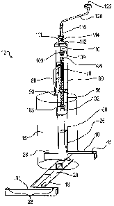
As illustrated in the accompanying drawing Figures, there is provided an
improved log splitting device generally identified by reference numeral 10.
Like
components or features are designated by like reference numerals, through the
various figures as described in greater detail hereinbelow.
As illustrated in Figure 1, the log splitting apparatus 10 includes a
horizontally
oriented supporting base including a primary frame or support member 20 having
opposed ends 22 and 24. Support for member 20, in use, acts as a log support
upon which a piece of wood or log is positioned for cutting and splitting. As
illustrated, support member 20 includes a vertically oriented projection or
extension 26 adapted to receive a further frame member, the vertically
oriented
projection 26 being located proximate one end of the member and slightly
spaced therefrom. As shown, member 26 is at a generally right angle to the
surface of the support member 20.
In a preferred embodiment, member 26 includes at least one aperture or other
similar means to releasably secure the further frame member thereto, such that
the further member may be raised or lowered in order to adjust the height of
the
other frame member.
5
CA 02588360 2007-05-11
The opposed ends of the support member 20 are adapted to receive a pair of
horizontally oriented end members 30 and 40, which as illustrated, are of a
generally T- shaped configuration and are adapted to be removably attached to
opposed ends 22 and 24. End member 30 and 40 include a projection or
extending member (32 and 42, respectively) for insertion into support member
20.
As illustrated in Figure 1, the supporting base is adapted to provide a stable
support upon which the weight of a log or piece of wood to be cut rests and is
cut
and/or split thereupon. As shown, member 20 is in an "in use" orientation, or
horizontally disposed, with the end members 30 and 40 extending providing a
stable base with the projection or extension 26 extending generally vertically
from
the frame member. In a preferred embodiment, the frame members are tubular
members, and may be of a suitable material, such as metal, steel, alloys,
plastic,
etc., or other suitable material known in the art.
As illustrated in the drawing figures, and in particular Figures 1 and 2, the
base or
frame members include suitable apertures or other means to releasably engage
with the corresponding or mating frame members such that the log splitter is
able
to be quickly assembled and disassembled for storage or transportation. As
illustrated, base or frame members 20, 26, 30 and 40 include apertures 18
through which pins or other locking means can be inserted to releasably secure
the assembly for use. As illustrated, the end members 30 and 40 may also
include apertures 28 adapted to receive nails, stakes or other suitable means
to
secure the base of the apparatus into the ground, such as when camping, to
increase the stability of the apparatus.
In a preferred embodiment, vertically extending projection 26 is adapted to
receive a first supporting member or inner tubular portion 50. Supporting
member
50 is releasably connected to extension 26 to support thereon a secondary
6
CA 02588360 2007-05-11
supporting member, discussed in greater detail below. As illustrated, the
inner
tubular member 50 includes opposed ends 52 and 54, where open end 52 is
adapted to be placed over the projection 26 and secured thereto, such as
through the use of suitable pins 18 or other locking means. Locking means or
pins 18 permit member 50 to be raised or lowered in relation to member 26, in
order to accommodate larger or smaller sized logs or pieces of wood to be cut
or
split.
Opposite end 54 is adapted to receive the mechanical drive means, discussed in
greater detail below. In a preferred embodiment, the inner tubular portion 50
includes proximate end 54 detent means, such as indentations 56, about the
periphery, best seen in Figure 2. Indentations 56 cooperate with the
mechanical
drive means, discussed below.
The apparatus 10 includes an outer or secondary supporting member 60, located
in operative relationship with the tubular member 50. The outer tubular member
60 is adapted to be placed over the inner tubular member 50. As illustrated in
the
Figures, and more particularly Figure 2, member 60 includes opposed ends 62
and 64. End 62 is adapted to matingly correspond with member 50 and when
assembled, slides over end 54 into an operative position thereon. End 64 is
adapted to receive an assembly cap 112 which helps secure and house the
brake nut assembly 111.
Mounting means 70 is provided to releasably secure the splitting wedge or axe
head 80. As illustrated, mounting means 70 includes mounting plate 72 attached
or otherwise secured to the outer tubular member 60. The plate 72 preferably
includes a groove or track 74 which releasably engages with the splitting
wedge
80. This allows for easy removal of the wedge 80 for sharpening or
replacement.
Preferably, the mounting plate 72 further includes a spring button 76 to allow
the
wedge or axe head 80 to be easily removed or installed. The axe head 80 may
7
CA 02588360 2007-05-11
be of a common shape (i.e., wedge shaped) and is adapted to slide into the
track
of the mounting bracket. The blade portion 90, when in use, is adapted to cut
into
the piece of wood 15 to effect splitting of the wood.
In a preferred embodiment, a mechanical drive means generally referred to by
reference numeral 100 is adapted to tubular member 50 which is secured therein
via detent means or indentations 56. As illustrated, the preferred embodiment
of
the mechanical drive means 100 includes at one end thereof a ball screw end
stop 102, suitable torque absorber 103 and a screw rod 104 to which is
attached
at the opposite end thereof a ball screw nut or other similar means 106 and a
screw or ball screw mounting plate 108 and a suitable torque absorber 103, and
a shaft collar 109. As illustrated, the ball screw plate rests against
indentations
56.
Outer or secondary tubular member 60 is adapted for placement over inner tube
50, all of which is secured via assembly cap 112 through member 109 to the
mechanical drive means inside tubular member 50. Assembly cap 112 includes
an upper portion 114 including an aperture which is adapted to house a backnut
brake assembly 111 and to receive a further assembly 116 which is adapted to
receive a crank arm 120 including handle 122 for manual actuation of the
mechanical drive means to raise and lower the outer tubular portion 60 to
effect
the cutting and splitting of a piece of wood or log 15. Mechanical drive means
100, when in use exerts constant pressure or force via the wedge 80 on to the
piece of wood or log 15. Member 116, in a preferred embodiment, is preferably
a
male hex or other similar means which is an operative relationship with the
drive
screw of the mechanical drive.
As such, the mechanical drive is adapted that it can be manually raised or
lower
by means of a removable/swivel type handle such as the crank arm 120 and
handle 122 as illustrated in Figure 2. Alternatively, the drive may also be
actuated through the use of a ratchet and socket, adjustable wrench, or open
8
CA 02588360 2007-05-11
ended wrench. Further, a drive bit may be used in combination with an electric
motor such as attached to a drill or other means to effect the raising and
lowering
of the wedge into the piece of wood.
In operation and use, the apparatus 10 is positioned on the ground or other
generally horizontal surface with the base members 20, 30 and 40 supporting
the
generally vertically extending members 50 and 60. A log or other piece of wood
is then placed immediately below the wedge 80 on top of horizontally
extending member 20 and maintained in such a position while a user, either
10 manually or otherwise, lowers the axe head to engage the blade portion 90
to the
upper surface of the log 15. As illustrated, the blade 90 contacts the piece
of
wood or log 15 at the edge of the log. In particular, the wedge via blade 90
engages the outer circumference of the log to be split when the log is placed
between the frame 20 and the wedge 80.
In operation, a user then may actuate the mechanical drive means to effect
lowering of the outer tubular member 60 about the lower or inner member 50 to
cut and split the piece of wood via wedge 80 to begin splitting and cutting of
the
log 15. As the user manually or otherwise actuates or effects movement of the
drive, this causes the splitting wedge or axe to apply a constant force to
cause
the piece of wood 15 to split. The user continues this action until the wedge
splits
the log 15. Advantageously, it has been found that the use of the tubular
frame
20 assists in localizing the force exerted by the wedge 80 to the log 15 thus
assisting in a more efficient split and cut of the piece of wood or log 15. As
noted
hereinabove, the constant pressure exerted by the mechanical drive means via
the wedge 80 to the piece of wood 15 applies a constant force engaging at
least
a portion of the outer circumference of the log to effect a more efficient
splitting
and cutting of the wood.
The height of the first tubular member 50 may be raised or lowered via locking
means (for example pins 18) releasably inserted in to apertures 18 to
9
CA 02588360 2007-05-11
accommodate different sizes or pieces of wood to be cut. This allows the
height
of the member 50 to be quickly and securely adjusted to different sizes of
logs or
wood. Through the continued manual actuation of the mechanical drive means
results in the wedge completely splitting the log or piece of wood. The split
portions of the piece of wood or log 15 typically fall to either side of the
generally
horizontal member 20 after which the wedge can be manually or otherwise
mechanically raised to accommodate a new log to allow the user to repeat the
process to cut and split additional pieces of wood.
In an alternative embodiment, the user operated handle may be replaced with
motorized means to effect the raising and lowering of the wedge. This may be
powered through a motor, drill or other suitable drive means.
The base 20 preferably includes means to allow the apparatus to be used free
standing, or in an alternative embodiment, wall or floor mounted with the use
of
suitable brackets or mounting means. Alternatively, the apparatus 10 may be
used in combination with a conventional hitch receiver of a vehicle.
In an alternative embodiment, the backnut brake assembly 111 may be located
within an upper part of the outer member 60, for example, resting on a plate
that
is fastened (through suitable means such as welding) to the inside of the
outer
member at a desired height. Alternatively, indentations or other suitable
means
could be provided to hold the plate in place. In a further preferred
embodiment,
the end cap assembly 112 may be smaller cap, such that it could be separate
from the backnut brake assembly.
In a further alternative aspect, flange bearings or similar means may be
provided
to assist the torque absorbers 103 to allow the ballscrew to be free turning
once it
bottoms or tops out. Desirably, a further flange bearing could be added to the
shaft 110 to prevent the shaft collar 109 from being in constant contact with
the
top of the outer member, thus preventing metal-to-metal contact.
CA 02588360 2007-05-11
As noted above, the present invention provides advantages over the prior art
and
for that matter other hand tools as commonly used to split or cut wood such as
an axe or splitting wedge. The present invention also provides a safer device
and
method for splitting wood than, for example, someone using an axe to split the
wood which could potentially cause injury by users who are unskilled or
inexperienced with the proper use of an axe or splitting wedge.
While one embodiment of the present invention has been described in the
foregoing description, it is to be understood that other embodiments are
possible
within the scope of the claimed invention.
11