Note : Les descriptions sont présentées dans la langue officielle dans laquelle elles ont été soumises.
CA 02590037 2009-03-10
-1-
APPARATUS FOR MANUFACTURING ROD-SHAPED SMOKING ARTICLES
Technical Field
The present invention relates to an apparatus for
manufacturing rod-shaped smoking articles such as
cigarettes and substitutive cigarettes, and more
specifically, to a manufacturing apparatus capable of
adding an additive to smoking material for rod-shaped
smoking articles.
Background Art
For instance, Japanese Patent No. 3472591 (published as Japanese
Patent application no. 06-007139 on January 18, 1994) discloses a
substitutive cigarette. This substitutive cigarette
includes a fuel element and an aerosol-generating chip.
The fuel element and the aerosol-generating chip are each
formed into a rod. When the substitutive cigarette
disclosed in the document is smoked, the fuel element is
first ignited. The burning heat of the fuel element heats
the aerosol-generating chip, and the heated aerosol-
generating chip generates aerosol. Such aerosol is inhaled
by a smoker through a filter of the substitutive cigarette.
An aerosol-generating source disclosed in the document
is produced by the following procedure.
First, filling material obtained by adding an aerosol-
generating substance to particles of smoking material is
prepared. Such filling material is supplied to a
manufacturing apparatus with a wrapping material, or web.
The manufacturing apparatus wraps the filling material in
the web and forms an aerosol-generating rod. Thereafter,
CA 02590037 2009-03-10
-2-
the aerosol-generating rod is cut into pieces of a given
length, and in result, discrete aerosol-generating chips
are obtained.
Since the filling material is prepared outside the
manufacturing apparatus, the manufacture of substitutive
cigarettes requires a preparation device for preparing the
filling material in addition to the manufacturing apparatus.
Equipment for manufacturing substitutive cigarettes is
therefore large-scale.
For that reason, it can be considered to prepare a
solution containing an additive such as an aerosol-
generating substance and to add this solution to the
smoking material in the manufacturing apparatus.
For the addition of the solution to the smoking
material, technologies disclosed, for example, in Japanese
Patent Application Publication No. 53-18800 published February 21, 1978
and Japanese Patent No. 3209985 (published as Patent Application No.
2000-106860 of April 18, 2000) can be employed. The former technology
discharges solution such as water from the inside of a
tongue arranged in a manufacturing apparatus, and by so
doing, prevents a gum-like film from being formed in the
inside of the tongue. The tongue compresses and molds the
smoking material into a rod in cooperation with a molding
bed and garniture tape of the manufacturing apparatus
before the smoking material is wrapped in the web.
According to the latter technology, when the smoking
material is sucked in layers by a suction band of the
manufacturing apparatus, and this material layer is
injected with a liquid flavor additive.
CA 02590037 2009-03-10
-3-
However, both the technologies have only one injection
position for an additive in a transfer path of the smoking
material, so that they are not capable of efficiently
adding the additive to the smoking material running through
the transfer path at high speed.
Furthermore, if the former technology is employed, a
liquid additive discharged from the tongue is contained
only in the upper portion of the rod-shaped smoking
material. Accordingly, when the rod-shaped smoking
material is subsequently wrapped in the web, and the
aerosol-generating rod is produced, a lap portion formed by
superposing the side edges of the web on each other gets
damp too much with the liquid additive. As a result, an
adhesion defect is prone to occur in the lap portion, so
that it is impossible to stably produce the aerosol-
generating rod, or rod-shaped smoking article.
If the latter technology is employed, in a process of
forming a material layer on the suction band, the liquid
additive is injected into the material layer. Therefore,
the unit length weight of the material layer becomes heavy,
and moreover, the injected liquid additive hampers the
suction band from sucking the smoking material.
Consequently, the formation of the material layer, namely
that of the rod-shaped smoking article, becomes unstable.
Disclosure of the Invention
It is an object of the present invention to provide an
apparatus for manufacturing rod-shaped smoking articles,
which is capable of effectively adding a liquid additive
into smoking material while securing stable manufacture of
the rod-shaped smoking articles.
CA 02590037 2009-03-10
-4-
In order to accomplish the object, the invention relates to an
apparatus for manufacturing rod-shaped smoking articles of the present
invention,
said apparatus comprising:
a forming section including a forming path, for forming a material layer made
up of particles of smoking material on the forming path, and delivering the
material
layer along the forming path, said forming section further including a pair of
guide
members disposed in the terminal end portion thereof, for guiding both sides
of the
material layer;
a wrapping section including a wrapping path, for receiving the material layer
from the forming path of said forming section, forming a rod in which the
material
layer is continuously wrapped in a web in the process where the material layer
travels along the wrapping path, and delivering the formed rod, said wrapping
section in which the rod has a lap portion formed by bonding both side edges
of the
web together in a state where the side edges are superposed upon each other;
a cutting section for cutting the rod delivered from said wrapping section
into
rod-shaped smoking articles having given length; and
an addition device for adding a liquid additive to the material layer in an
area
between a terminal end portion of the forming path and a start end portion of
the
wrapping path, wherein:
said addition device is disposed in the area and includes a plurality of
injection openings for injecting the additive into the material layer and the
injection openings are spaced from each other in a traveling direction of the
material layer and also in a circumferential direction of the material layer;
said wrapping section further includes:
a compression member disposed in the start end portion of the
wrapping path, for compressing the material layer from above, and
a web shield located in a start end portion of the wrapping path, for
separating the material layer and the web from each other, said web shield
extending from the start end portion. _of the wrapping path toward said
CA 02590037 2009-03-10
.
-5-
compression member and partly overlaps with said compression member,
and
at least two among the guide member, the compression member and the
web shield have respective injection openings.
In the above-mentioned manufacturing apparatus, when
the material layer runs through the area between the
terminal end portion of the forming path and the start end
portion of the wrapping path, the liquid additive, or more
specifically, a liquid flavor additive containing alcohols,
is injected from the injection openings into the material
layer. For example, glycerin, propylene glycol (PG),
menthol dissolved in alcohol or the like may be used as a
liquid flavor additive of the above-mentioned kind.
Since the injection openings are spaced from each
other in the traveling and circumferential directions of
the material layer, the additive can be efficiently
injected into the material layer.
The injection openings are located in the area between
the terminal end portion of the forming path and the start
end portion of the wrapping path. Therefore, the injection
of the additive does not adversely affect the formation of
the material layer on the forming path. Moreover, it is
possible to easily secure spaces for the injection openings.
Since the addition device has the plurality of
injection openings, a total injection amount of the
additive required in the material layer can be apportioned
to each injection opening, which makes it possible to
reduce an injection amount of the additive to be injected
from each injection opening.
More specifically, the forming section may include a
of members dis osed in the terminal end
pair guide p portion
of the forming path, for guiding both sides of the material
CA 02590037 2009-03-10
- 5a -
layer. The wrapping section may further include a
compression member disposed in the start end portion of the
wrapping path, for compressing the material layer from
above and a web shield placed in the start end portion of
the wrapping path,-for separating the material layer and
the web from each other. In this case, at least two among
the guide member, the compression member and the web shield
have the respective injection openings.
In this case, the injection openings of the guide
member, the compression member and the web shield can
inject the additive into the material layer from the sides,
above and beneath of the material layer.
In a case that the compression member has the
injection opening, the injection opening is preferably
positioned so as to avoid a portion of the material layer,
which is covered with the lap portion of the web, the injection opening of the
compression member injects the additive into the material layer on said web
shield. In this case, the injected additive never wets the lap portion of
the web. However, when the web shield has the injection
opening, the injection opening is preferably positioned
upstream from the compression member as viewed in the
traveling direction of the material layer. Again, the
injected additive never humidifies the web.
Since the web and the lap portion of the web do not
get damp with the additive, the rod is stably formed.
CA 02590037 2007-06-11
- 6 -
Furthermore, when the material layer passes the
injection opening of the web shield, the material layer is
not compressed yet. This makes it possible to inject the
additive into material layer through the injection opening
of the web shield without difficulty.
The addition device may further include regulation
means for controlling the injection amount of the additive
to be injected from the injection openings according to
traveling speed of the rod. In this case, the addition
device can evenly add the additive into the rod-shaped
smoking article regardless of speed of manufacturing the
rod.
The addition device may further include control means
for intermittently halting the injection of the additive
for the purpose of avoiding the injection of the additive
into predetermined cut points of the rod. In this case,
the addition device prevents the additive from adhering to
a cutter of the cutting section.
As the injection opening, a jet orifice of a spray
nozzle or a discharge orifice of a microsolenoid valve may
be used. The spray nozzle and the microsolenoid valve are
small in size, so that they can be disposed near a travel
path of the material layer.
The above-mentioned additive is a liquid flavor
additive containing an alcohol. Liquid flavor additive of
this kind may include, for example, glycerin, propylene
glycol (PG), or menthol dissolved in alcohol, etc.
Brief Description of the Drawings
FIG. 1 is a view schematically showing a configuration
of a manufacturing apparatus;
FIG. 2 is a view showing a part of the manufacturing
apparatus of FIG. 1 in an enlarged scale;
FIG. 3 is a cross sectional view of a guide block
CA 02590037 2007-06-11
- 7 -
disposed in a terminal end portion of a molding path of FIG.
2;
FIG. 4 is a cross sectional view showing a web shield
of FIG. 2;
FIG. 5 is a cross sectional view, taken along line
crossing in an upstream end of a tongue of FIG. 2;
FIG. 6 is a cross sectional view of a rod;
FIG. 7 is a view showing areas applied with a liquid
flavor additive and areas not applied with a liquid flavor
additive in the rod;
FIG. 8 is a view showing a spray nozzle having a jet
orifice; and
FIG. 9 is a view showing a microsolenoid valve having
a discharge orifice.
Best Mode of Carrying out the Invention
FIG. 1 schematically shows an apparatus for
manufacturing rod-shaped smoking articles.
The manufacturing apparatus has the same configuration
as a configuration of an apparatus for manufacturing
cigarette rods. Therefore, the basic configuration of the
manufacturing apparatus will be briefly described below.
The manufacturing apparatus has a forming section 10
for a material layer. The forming section 10 is placed on
the right side of FIG. 1. The forming section 10 has an
endless suction band 12. The suction band 12 extends
between a driving roller 14 and a driven roller 16. The
rollers 14 and 16 are spaced from each other in a
horizontal direction. When the driving roller 14 is
rotated, the suction band 12 runs in one direction, and a
lower band portion of the suction band 12 forms a forming
path for the material layer.
A chimney 18 is disposed immediately under the suction
band 12 so as to be located on the side of the driven
CA 02590037 2007-06-11
- 8 -
roller 16. Particles of smoking material are supplied from
a supply source, not shown, into the chimney 18. The
chimney 18 blows up the smoking material contained in the
inside thereof toward the suction band 12.
The smoking material that has been blown up is sucked
by the running suction band 12 to be stratified on a lower
surface thereof. This forms a material layer K on the
suction band 12. Accordingly, the material layer K
proceeds with the suction band 12 and is transferred in the
left direction in FIG. 1.
The smoking material here is shred tobacco obtained by
cutting a sheet-like reconstituted tobacco, shred tobacco
subjected to an expanding process or a mixture of these two
kinds of shred tobacco.
A wrapping section 20 is adjacently disposed at the
left side of the forming section 10.
The wrapping section 20 includes endless garniture
tape 22. The garniture tape 22 extends between a pair of
tape rollers 24 and 26. The tape rollers 24 and 26 are
also spaced from each other in the horizontal direction.
An upper tape portion of the garniture tape 22 passes over
a bed, not shown, and forms a wrapping path in cooperation
with a molding groove of the bed. The wrapping path
horizontally extends in alignment with the forming path.
There is secured given space between a start end portion of
the wrapping path and a terminal end portion of the forming
path.
A lower tape portion of the garniture tape 22 is
guided by a plurality of guide rollers 28 and passes around
a tape drum 30. The garniture tape 22 runs when the tape
drum 30 is rotated. The tape drum 30 is rotated by a motor,
not shown. Rotation of the motor is controlled by an
electronic control unit (ECU) 32.
CA 02590037 2007-06-11
- 9 -
The tape drum 30 has a drum shaft to which a rotary
encoder 34 is fixed. The rotary encoder 34 detects
rotation speed of the tape drum 30, namely, running speed
of the garniture tape 22, and supplies a signal indicative
of the running speed to the electronic control unit 32.
There is disposed a roller-shaped web guide 36 in
between the start end portion of the wrapping path and the
terminal end portion of the forming path. The web guide 36
directs web W such as paper that is drawn out from a web
roll onto the upper tape portion of the garniture tape 22.
The wrapping section 20 includes a shoe 38 and a
tongue 40 in the start end portion of the wrapping path.
The shoe 38 and the tongue 40 are successively arranged in
the order named from the driving roller 14 side. The shoe
38 has a wedge-shaped edge located close to the driving
roller 14 and peels off the material layer K from the
suction band 12. The material layer K that has been peeled
off is supplied onto the web W in the start end portion of
the wrapping path.
After being transferred onto the web W, the material
layer K passes through the tongue 40 with the garniture
tape 22 and the web W as the garniture tape 22 runs. In
this process, the tongue 40 compresses the material layer K
from above in cooperation with the bed and forms an upper
portion of the material layer K into a circular arc in
cross-section.
In the process where the garniture tape 22 runs from
the start end portion of the wrapping path toward the
tongue 40, the molding groove of the bed gradually forms
the garniture tape 22, or web W, in the shape of letter U
in cross-section. As a result, the molding groove
compresses a lower portion of the material layer K in
cooperation with the tongue 40 and molds the lower portion
CA 02590037 2007-06-11
- 10 -
into a circular arc in cross-section. In short, the
material layer K is compressed from above and beneath to be
formed into a rod-shape.
In the wrapping path, a short holder 42, a long holder
44 and a heater unit 46 are successively arranged
downstream of the tongue 40. When the web W passes through
the short holder 42 and the long holder 46 with the
material layer K, the holders 42 and 44 continuously wrap
the material layer K in the web W through the garniture
tape 22, to thereby form a rod KR.
More specifically, the short holder 42 bends one side
edge of the web W in the shape of a circular arc so that
the one side edge of the web W is placed over the material
layer K. In this process, the other side edge of the web W
is applied with glue by a glue-application nozzle, not
shown. Subsequently, the long holder 44 bends the other
side edge of the web W in the circular arc-like shape as
with the one side edge and places the other side edge of
the web W over the material layer K. As a result, both the
side edges of the web W are superposed on each other and
bonded together with glue, thereby forming a lap portion of
the rod KR.
Thereafter, when the rod KR passes through the heater
unit 46, the glue applied to the lap portion is dried by
the heater unit 46. The rod KR is then continuously
delivered from the wrapping section 20.
A cutting section 48 is placed downstream of the
wrapping section 20. The cutting section 48 includes a
cutter casing 50 that allows the rod KR to pass
therethrough and a rotatable cutter disc 52 contained in
the cutter casing 50. The cutter disc 52 has one or more
cutter blades, not shown, in an outer circumferential edge
thereof. The cutter blades are arranged at regular
CA 02590037 2007-06-11
- 11 -
intervals in a circumferential direction of the cutter disc
52.
The rod KR is cut into pieces with given length as the
cutter disc 52 rotates. This produces discrete rod-shaped
smoking articles A. The cutter disc 52 and the tape drum
30 are connected to each other through a power transmission
path, not shown. The cutter disc 52 rotates at rotation
speed corresponding to rotation speed of the tape drum 30,
namely, running speed of the rod KR. Consequently, the
cutter disc 52 can cut the rod KR into pieces with given
length regardless of the running speed of the rod KR.
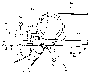
FIG. 2 shows in more detail an area between the
terminal end portion of the forming path to the start end
portion of the wrapping path.
The forming path has a pair of guide blocks 54 in the
terminal end portion thereof. The guide blocks 54 are
arranged in both sides of the forming path under the
driving roller 16, to thereby guide both sides of the
material layer K.
A web shield 56 extends from the guide blocks 54
toward the tape roller 24 of the wrapping path. The web
shield 56 is spaced apart with a given gap from the web W
between the web guide 36 and the tape roller 24. The web
shield 56 guides the shred layer K to transfer from the
forming path onto the web W and separates the web W and the
material layer K from each other until the web W is
superposed on the garniture tape 22.
As is apparent from FIG. 2, the tongue 40 extends over
the tape roller 24 and the web guide 36, and has an
upstream end that is located above the web guide roller 36.
The guide blocks 54, the web shield 56 and the tongue
are provided with respective injection openings of an
addition device 57 of one embodiment. The addition device
CA 02590037 2007-06-11
- 12 -
57 will be described below.
The addition device 57 includes an electromagnetic-
activation injector 58. The injector 58 is fixed to an
outer surface of one of the guide blocks 54. The injector
58 has a supply port, which is connected to an additive
supply source, or more specifically to a flavor additive
supply source 60, through a supply hose. The flavor
additive supply source 60 stores a liquid flavor additive
such as menthol that is dissolved, for example, in glycerin,
propylene glycol (PG) or alcohol. The liquid flavor
additive is in a pressurized state in the flavor additive
supply source 60. Therefore, the liquid flavor additive is
directed from the supply source 60 through the supply hose
to the injector 58. The injector 58 is filled with the
liquid flavor additive.
The injector 58 is electrically connected to the
electronic control unit 32. The electronic control unit 32
supplies a control signal toward the injector 58, to
thereby control opening and closing of the injector 58.
When opened, the injector 58 ejects the liquid flavor
additive from a jet orifice thereof.
As is obvious from FIG. 3, the jet orifice of the
injector 58 is connected to an inner channel 62 of the
guide block 54. The inner channel 62 has an injection
opening 64 that opens in an inner surface of the guide
block 54. Accordingly, the liquid flavor additive ejected
from the jet orifice of the injector 58 is injected from
the injection opening 64 into the material layer K through
the inner channel 62.
As shown by an arrow in FIG. 3, it is possible to
inject the liquid flavor additive into the material layer K
from the other guide block 54. In this case, another inner
channel with an injection opening is formed in the other
CA 02590037 2007-06-11
- 13 -
guide block 56. This inner channel is connected to the
flavor additive supply source 60 through an injector
similar to the above-mentioned injector.
The addition device 57 includes an electromagnetic-
activation injector 66 that is fixed to an outer surface of
the web shield 56. The injector 66 is also connected to
the flavor additive supply source 60 and the electronic
control unit 32. As is clear from FIG. 4, there is formed
an inner channel 68 -in the web shield 56. The inner
channel 68 is connected to a jet orifice of the injector 66
and has an injection opening 70 that opens in an upper
surface of the web shield 56. Therefore, when the injector
66 is opened, the liquid flavor additive is ejected from
the injection opening 70. The ejected liquid flavor
additive is injected into the material layer K from a lower
surface of the material layer K. As is apparent from FIG.
2, the injection opening 70 is located immediately above
the web guide 36.
As illustrated in FIG. 5, the addition device 57
includes an electromagnetic-activation injector 72 that is
fixed to an outer surface of the tongue 40. The injector
72 is mounted on an upper surface of an upstream end of the
tongue 40. The injector 72 is also connected to both the
flavor additive supply source 60 and the electronic control
unit 32. A jet orifice of the injector 72 is connected to
an inner channel 74 formed in the tongue 40. The inner
channel 74 has an injection opening 76 that opens in a
lower surface of the tongue 40. When the injector 72 is
opened, the liquid flavor additive is ejected from the
injection opening 76. The ejected liquid flavor additive
is injected into the material layer K from an upper surface
of the material layer K.
As is evident from FIG. 5, the injection opening 76 is
CA 02590037 2007-06-11
- 14 -
located so as to deviate from the center of a lower surface
of the tongue 40, avoiding the center of the lower surface
of the tongue 40. For this reason, when the rod KR is
molded, it is possible, as illustrated in FIG. 6, to inject
the liquid flavor additive into the material layer K from
the injection opening 76 while avoiding a region of the
material layer K which is covered with the lap portion L of
the web W.
The electronic control unit 32 controls amount of the
liquid flavor additive that is injected from the injectors
58, 66 and 72 into the material layer K. More specifically,
the electronic control unit 32 increases or decreases
opening of each injector according to the running speed of
the garniture tape 22, or of the rod KR. Therefore, the
injectors 58, 66 and 72 can inject the liquid flavor
additive evenly per unit length of the material layer K.
Based upon cut timing of the rod KR, the electronic
control unit 32 activates the injectors 58, 66 and 72 so
that they are closed intermittently and individually, and
discontinues the injection of the liquid flavor additive
from the injection openings 64, 70 and 76 into the material
layer K. As a result, as illustrated in FIG. 7, addition
areas added with the liquid flavor additive, which are
shown with slant lines, and non-addition areas that are not
added with the liquid flavor additive, which are shown in
white, are alternately formed in the material layer K of
the rod KR. An interval between the two adjacent non-
addition areas is equal to length of a single rod-shaped
smoking article A. The rod KR is cut in the center of the
non-addition area, that is, at a cutting position CP. In
this manner, the discrete rod-shaped smoking articles A are
produced from the rod KR. As viewed in the running
direction of the material layer K, the injection openings
CA 02590037 2007-06-11
- 15 -
64, 70 and 76 are located in different positions, so that
timing in which the injectors 58, 66, 72 are activated into
the closed positions is individually determined in
accordance with distances between the respective injection
openings and the cutter disc 52 in the cutting section 48
and the running speed of the material layer K.
As evidenced by the foregoing explanation, since the
three injection openings 64, 70 and 76 are spaced from each
other in the running and circumferential directions of the
material layer K, the material layer K receives the
injection of the liquid flavor additive from different
positions. Therefore, the amount of the liquid flavor
additive to be injected from each of the injection openings
into the material layer K is reduced to one third of total
addition amount of the liquid flavor additive required in
the material layer K. Consequently, even if the material
layer K runs at high speed, it is possible to fully enhance
the efficiency of addition of the liquid flavor additive
into the material layer K.
TABLE 1 below shows results of measurement in which
the efficiency of addition of the liquid flavor additive
was measured in respect to various cases where the number
of the injection openings, the disposition of the injection
openings, and injection amounts of the liquid flavor
additive injected from the injection openings are varied.
TABLE 1 also shows evaluations of flavor and taste of the
rod-shaped smoking articles A.
CA 02590037 2007-06-11
- 16 -
44
o 0
- 4+ uo u7 Ln Ln un u-)
41
0, (~ C; . 'T 1, 'r . . ~r . .
~ d M ~ M
w
0
U ~ CO lfl r I 00 CSl lfl l- O tf) 00 f--i [-
~ AJ CO CO 61 00 OO 61 00 M Ol 00 61 61
=rl
O O O O O O O O O O O O
-~
W
W
T3
r-I
-H
~ I I I ~ ~ ~ I I N I I ~
.~ .~ m
v
4J
~
0
U
0
O ~ M t1~
-r-1 ~ O O = = i.n if) l-
U ~ I O ~ ~ N N 1-1
M (n
-n ='-1
H
~
.~
~
U)
04
0
O ~ p (M Lf)
U O O I tf) ~
H M M
-r-~
4--)
W 41
O F.
O
O
-rl
+)
0 ~ O
U Ln
rl =N
W =-I
ro
o
`-' H
CA 02590037 2009-03-10
-17-
The efficiency of addition indicates proportion of
content of the liquid flavor additive in the rod-shaped
smoking article A to the injection amount of the liquid
flavor additive injected from the injection opening. When
the. rod-shaped smoking article A was evaluated,
substitutive cigarettes as disclosed in Japanese Patent No.
3472591 (Japanese Patent Application published under No. 06-007159 on
January 18, 1994) were produces using the rod-shaped smoking article
A, and the substitutive cigarettes were smoked by three
evaluation experts. When smoking, the experts judged mass
of aerosol containing a flavor additive generated from the
rod-shaped smoking article A, that is, mass of a mainstream
smoke of the substitutive cigarettes. The result of this
judgment is the evaluation of the rod-shaped smoking
article A. The experts made the judgment on a scale of one
to ten, with 5 being the highest score.
As is obvious from TABLE 1, both the efficiency of
addition of the liquid flavor additive and the evaluation
of a smoking flavor are high in proportion to the increase
of the number of the injection openings. Regarding the
total injection amount of the liquid flavor additive, the
evaluation is high as the total injection amount is
increased.
If the guide block 54, the web shield 56 and the
tongue 40 have the injection openings 64, 70 and 76,
respectively, the material layer K receives the injection
of the liquid flavor additive from three places, that is,
lateral, lower and upper surfaces thereof. Therefore, the
injected liquid flavor additive is more evenly distributed
in the material layer K. This is a significant factor for
high scores on the evaluation of the rod-shaped smoking
article A.
The injection openings 64, 70 and 76 are all disposed
in an area between from the terminal end portion of the
CA 02590037 2007-06-11
- 18 -
forming section 10 to the start end portion of the wrapping
section 20. For this reason, the injection of the liquid
flavor additive from the injection openings 64, 70 and 76
does not adversely affect the forming of the material layer
K, so that the material layer K is stably formed on the
suction belt 12.
When the liquid flavor additive is injected from the
injection opening 70 into the material layer K, the web
shield 56 prevents the web W from directly getting wet with
the liquid flavor additive. In addition, when the liquid
flavor additive is injected from the injection opening 76
into the material layer K, the lap portion L of the rod KR
does not get wet with the liquid flavor additive.
Accordingly, there generates no tear in the web W or poor
adhesion in the lap portion L. It is possible to stably
perform the wrapping of the material layer K in the web W,
that is, the forming of the rod KR.
Since the injection openings 70 and 76 are arranged
upstream from the tongue 40, the material layer K is not
compressed by the tongue 40 when passing through the
injection openings 70 and 76. Consequently, the liquid
flavor additive ejected from the injection openings 70 and
76 is injected into the material layer K without difficulty.
The amount of the liquid flavor additive that is
injected from the injection openings 64, 70 and 76 into the
material layer K is increased or decreased according to the
running speed of the material layer K. As a result, the
amounts of the liquid flavor additive that is added into
the respective rod-shaped smoking articles A are the same
regardless of speed of manufacturing the rod KR.
Since the rod KR is cut in the non-addition areas (see
FIG. 7) that are not added with the liquid flavor additive,
the liquid flavor additive does not adhere to the cutter
CA 02590037 2007-06-11
- 19 -
blade of the cutter disc 52 during cutting. Consequently,
the cutter blade is not deteriorated in durability.
The present invention is not limited to the foregoing
one embodiment, and may be modified in various ways. For
instance, the addition device 57 may include injection
openings provided to two of the guide block 54, the web
shield 56 and the tongue 40.
As illustrated in FIGS. 8 and 9, the inner channel may
have a spray nozzle 78 or a solenoid valve 82 in the
opening end thereof. In this case, a spray orifice 80 of
the spray nozzle 78 or a discharge orifice 84 of the
microsolenoid valve 82 serve as an injection opening of the
addition device 57. Instead of the spray nozzle 78 and the
microsolenoid valve 72, an ink jet nozzle may be utilized.
The spray nozzle 78, the microsolenoid valve 82 or the ink
jet nozzle can be disposed close to the flow of the
material layer, as compared to the injectors 58, 66 and 72.
Accordingly, when the non-addition areas shown in FIG. 7
are secured, it is possible to form the non-addition areas
with high accuracy.
The manufacturing apparatus of the present invention
is applicable to manufacture of common cigarette rods,
other than the manufacture of elements of the substitutive
cigarettes. In that case, the material layer is made up of
a mixture of shred tobacco, shreds obtained by cutting a
sheet-like reconstituted tobacco, and shred tobacco
subjected to an expanding process. As to the liquid flavor
additive, a liquid flavor corresponding to a brand of the
cigarette rod is used.
When the liquid flavor is added to the material layer
on the manufacturing apparatus of cigarette rods, it is
possible to omit the step of adding flavor to smoking
material using a rotor-type flavor adding machine and the
CA 02590037 2007-06-11
- 20 -
subsequent step of curing the smoking material by means of
a silo or the like.
Furthermore, the manufacturing apparatus of the
present invention may be used for addition of various kinds
of liquid additives other than liquid flavor additive.