Note : Les descriptions sont présentées dans la langue officielle dans laquelle elles ont été soumises.
CA 02590424 2007-05-31
WO 2006/058551 PCT/EP2004/013713
METHOD, SYSTEM AND DEVICE FOR IMPARTING A PREDETERMINED
ROTATION TO AN OPTICAL FIBRE
The present invention relates to the field of optical fibre processing, in
particular to the
techniques of optical fibre manufacturing wherein the optical fiber is rotated
about its
axis for lowering the polarization mode dispersion (PMD) of the optical fibre
or of an
optical link comprising the optical fibre.
More specifically, the present invention applies to any process in which an
optical fibre
is advanced in a predetermined direction and a rotation about its axis is
imparted to it
during its advance. This process may be, for example, a process for producing
an optical
fibre (typically a drawing process) or a process for manufacturing an optical
cable by a
plurality of optical fibres. In optical fiber and optical cable manufacturing,
various techniques are known for
applying a torsional rotation to an optical fiber about its axis. Such
rotation has been
demonstrated useful for various applications, such as for example for
manufacturing a
multimode optical fiber having an increased fiber bandwidth or for
manufacturing an
optical fiber, or an optical cable containing an optical fiber, having a
reduced
polarization mode dispersion (PMD).
It is known that the "single mode fiber" commonly used in communication
systems is
not purely single mode and that, rather, it supports two modes with
perpendicular
polarizations. These two polarizations form an orthogonal basis set and any
configuration of light that propagates through a single mode fiber can be
represented by
a linear superposition of these two modes.
If the fiber is perfectly circularly symmetric in both geometry (including
optical
properties such as the refractive index) and internal and applied stress, the
two
polarization modes are degenerate and propagate with the same group velocity.
However, a typical optical fiber is not perfectly circularly symmetric, in
part because of
various factors present during manufacturing. Imperfections, such as geometric
deformation and stress asymmetry, break the degeneracy of the two modes. For
example, the cross section of a typical optical fibre may be slightly
elliptical in shape.
CONFIRMATION COPY
CA 02590424 2007-05-31
WO 2006/058551 PCT/EP2004/013713
2
As a result, the two polarization modes propagate with different propagation
constants.
The difference between the propagation constants is termed birefringence.
Birefringence causes the polarization state of light propagating in the fiber
to evolve
periodically along the length of the fiber. The distance required for the
polarization to
retunl to its original state is the fiber beat length, which is inversely
proportional to the
fiber birefringence. Typical beat lengths observed in practice range from as
short as 2-3
millimetres (a high birefringence fiber) to as long as 10-100 meters (a low
birefringence
fiber).
In addition, the presence of birefringence means that the two polarization
modes travel
at different group velocities and have a time delay difference after
travelling the same
distance, the difference increasing as the birefringence increases. The
differential, time
delay between the two polarization modes is called polarization mode
dispersion, or
PMD, which typically scales as the square root of fiber length for long
distances (unit of
measure ps/Am). PMD causes signal distortion that is very harmful for high bit
rate
systems and analog communication systems. This phenomenon is therefore
undesirable
in systems of optical signal transmission, especially in those operating over
long
distances.
Various methods to reduce PMD have been disclosed which involve imparting a
rotation into the fiber during manufacturing. The rotation causes the
intenrnal geometric
and/or stress asymmetries of the fiber to rotate about the fiber's axis as one
progresses
down that axis. This assures that the asymmetries are 'averaged' during the
propagation
of the optical radiation along the fiber, thus reducing the impact of PMD.
More in
details, the rotation induces an internal coupling between the two
orthogonally polarized
modes.
A rotation imparted to a fiber may result in an imparted 'spin' or 'twist', or
a
combination thereof.
The 'spin' is a permanent torsional deformation impressed on the fiber when
the fiber
material in a hot zone is caused to be torsionally deformed, resulting in the
deformation
being frozen into the fiber as it cools from its molten state, without the
generation of
torsional stress.
CA 02590424 2007-05-31
WO 2006/058551 PCT/EP2004/013713
3
The 'twist' refers to the rotation introduced onto the cooled optical fiber.
In this case, a
combination of rotation of the asymmetries and of torsional stress will occur
because the
fiber becomes relatively rigid compared to its molten state. Twist can be
undone or
reduced by applying a rotation in the other direction, whereas spin is
permanent.
Extreme amounts of twist can cause microscopic cracks, and contribute or cause
the
ultimate physical destruction of the fiber. Consequently, it is desirable to
reduce or
eliminate twist introduced on the fiber. One method of reducing twist on
optical fiber is
to respool the fiber by unwinding it and rewinding the fiber.
Techniques have been developed which rely on spinning the fiber as it is drawn
(see,
e.g., patent application US2004/0163418). The process of drawing an optical
fibre is
typically carried out by heating a glass preform to a temperature above the
softening
point and drawing downwards the molten material so as to produce the optical
fibre
itself. The fibre is. then typically made to pass through a diameter monitor,
then through
a coating applicator, where a polymer coating is applied to the optical fibre
which has
now substantially cooled, and then through a coating concentricity monitor, a
curing
station and a coating diameter monitor. Below, drive and guide means pull the
fibre and
guide it towards a take-up spool. A spinning device is typically placed
downwardly the
coating apparatus and it may comprise for example a roller or other elements
apt to
impart an angular movement to the fiber and to provide spin. By performing the
spinning during drawing, i.e., when the root of the preform is substantially
molten,
essentially pure rotation is performed on the fiber asymmetries.
For the purpose of the present invention, the term 'spinning device' will
refer to any
device which is apt to impart to a fiber a torsional rotation about its axis,
independently
by the fact that it is used to impart a spin or a twist.
In the art, various techniques and devices for rotating an optical fiber are
known.
For example, US Patent 5,298,047 proposes a method for imparting a torque to
the
optical fibre during the drawing process, wherein the torque is imparted by
altering the
angle of take-up rollers, which pull the fiber from the preform, making a
guide roller of
the optical fibre, having its axis perpendicular to the axis of advance of the
fibre, move
in a suitable way, by alternate oscillations in the clockwise and counter-
clockwise
directions.
CA 02590424 2007-05-31
WO 2006/058551 PCT/EP2004/013713
4
Patent application US 6,324,872 proposes a spinning device (see Figs. 4
thereof)
comprising a pair of elements, located on opposite sides of the optical fibre
drawing
axis, each having its own surface region for contact with the fibre. At least
one of the
two surface regions is moved in a direction transverse to the direction of
drawing in
such a way that the two surface regions are in motion relative to each other
and therefore
impart to the optical fibre a rotation about its axis. For example, the pair
of elements
may consist of a pair of rollers with their axis of rotation perpendicular to
the drawing
direction, at least one of which is capable of moving in a reciprocating way
along its
own axis so as to impart an alternating spin to the fiber.
Generally, the amount of actual spin which is actually introduced into the
optical fibre is
different from the theoretical amount that would be introduced if 100% of the
rotation
would be transferred from the spinning device to the fiber. According to the
Applicant,
there are various known factors affecting the rotational transfer imparted
into the fiber,
for example:
- the long span of fiber between the neck-down region and the spinning device;
- the presence of devices along this span of fiber such as rollers or coating
apparatus,
which cause frictional forces to arise;
- the viscous drag characteristics of the coating;
- the viscous drag characteristic of the neck-down itself;
- temperature differential of the fiber along its length; and
- the undesired application of non-negligible twist by the drawing system.
Thus, while the spinning device imparts an angular movement at a given point
along the
draw line, a typically lower angular movement is imparted near the neck-down
region.
The Applicant has also observed that the above difference may also occur
because of
mechanical effects in the spinning device, e.g., slippage at the interface
between the
fiber and the spinning device. For example, the fiber may slip on the rollers
that impart
the spin.
The existence of the imparted spin can be readily ascertained, e.g., by
microscopic
examination of bubbles in the fiber to determine rotation of the core, or by
means of a
travelling magneto-optic modulator. An alternative technique for controlling
the internal
rotation of the principal axes of a birefringent optical fibre during the
process of
CA 02590424 2007-05-31
WO 2006/058551 PCT/EP2004/013713
fabricating the fibre consists in laterally illuminating the optical fibre
with a He-Ne laser
beam in such a way as to generate interference fringes by means of the
backscattered
light. A rotation of the optical fibre causes a shift of the fringes, owing to
the ellipticity
of the fibre or any anisotropy of the refractive index due to stresses. It is
then possible to
5 determine the rotation of the principal axes of birefringence of the optical
fibre by
measuring the shift of the fringes.
In Patent Application US2002/0178758 of the same Applicant, it is proposed a
technique for on-line measurement of the actual rotation imparted to an
optical fibre
during the processing of the fibre. The actual rotation imparted to the
optical fibre is
determined on the basis of the measurement of the diameter of the optical
fibre. This is
because, when the diameter of an optical fibre advancing in a predetermined
direction
and made to rotate about its axis is measured, the asymmetries and
anisotropies of the
optical fibre cause an oscillation of the measured value between a minimum and
a
maximum value, with a frequency which is correlated with the velocity of
rotation of the
fibre. This scheme uses real time Fourier analysis of the fiber diameter data
as obtained
by transverse on-line measurements of the optical fiber shortly after is it
drawn from the
preform. The system uses power spectrum analysis to correlate the signals with
the spin
rate.
The information on the spin rate has been used to retroactively control the
spin imparted
to the optical fibre, in such a way as to produce a fibre with an actual spin
corresponding
to the one predefined according to the specifications and therefore with a
predetermined
response in terms of PMD. In case of an alternate spin function (e.g.
sinusoidal) having
a time frequency of inversion v (in inverse seconds), a feed-back loop
controls,
responsively to the actual spin measurement data, the frequency of inversion v
of the
spinning device. Depending on the spinning device used, it has also been
suggested to
control the maximum excursion of the moving member of the spinning device
(called
'amplitude'), as an alternative or in addition to the variations of the
inversion frequency
V.
An alternative technique for real time determination of spin and twist rate
used to alter
the spin rate or draw rate is disclosed in Patent US 6,791,678, which is based
on
filtering the diameter measurement signal to get the spin or twist data.
CA 02590424 2007-05-31
WO 2006/058551 PCT/EP2004/013713
6
The Applicant has now found that controlling with a feed-back loop the
amplitude
and/or the inversion frequency of the spinning device could be not as
effective as
expected in order to guarantee the target spin rate. If the spinning device
does not work
properly, e.g. if the fiber interacts weakly with the spinning device, such a
feedback
action could fail to set the desired rotation of the fiber. Moreover, an
attempt to increase
the actual rotation simply by increasing the inversion frequency, as described
in cited
patent application US2002/0178758, could result in an increase of the
amplitude of
vibration of the fiber out of the drawing axis, so increasing the amount of
breaks during
drawing and/or during the subsequent mechanical screening.
The Applicant has also found that an additional problem affects the transfer
to the
optical fiber of the spinning function ideally imparted by the spinning
device. This
additional problem relates to the variation of the frictional force between
the optical
fiber and the spinning device during the processing of the fiber, thus causing
a variable
degree of slippage of the fiber on the spinning device. This problem may
affect the
actual rotation rate at an extent greater than the one that can be
counterbalanced by
controlling the amplitude and/or frequency spinning parameters.
The Applicant has found that controlling the amplitude and/or the frequency of
the
spinning device may be insufficient and that it is important to control the
frictional force
of the spinning device in order to suitably control the degree of slippage of
the fiber onto
the spinning device itself. This control of the slippage of the fiber may
exemplarily be
aimed at avoiding the slippage itself, or at reducing it at a suitable level.
The friction
control can be achieved via a feed-back loop fed by the on-line measurement of
the
actual rotation rate. The amplitude and/or frequency of the spinning device
may be
controlled in addition to the frictional force. In other words, the Applicant
has realized
that adjusting the frictional force responsively to a real time measurement of
the actual
spin imparted to the fiber with a feed-back system allows to timely adjust the
spinning
conditions so that the spin really obtained in the fiber satisfactorily
corresponds to the
target spin function designed for the fiber.
Patent application US 6,324,872, already cited, discloses that the two rollers
of the
spinning device are arranged at the same point along the longitudinal extent
of the fiber
path, on opposite sides of the path, so that the rollers define a nip
therebetween. A
CA 02590424 2007-05-31
WO 2006/058551 PCT/EP2004/013713
7
micrometer adjustment and locking device are provided for controlling the
position of
second roller in the cross-path directions. First roller is biased by a spring
in the cross-
path direction toward the second roller. An adjustable stop limits movement of
the first
roller in the cross-path direction. This stop assures that the distance
between the two
rollers will always be at least equal to a predetermined minimum, and thus
assures that
the rollers will not crush the fiber. If the diameter of the fiber is slightly
greater than this
predetermined minimum distance, the carriage will remain engaged with the
stop. The
resilient circumferential surfaces of the rollers will compress slightly, and
the fiber will
be forcibly engaged with both circumferential surfaces. If the fiber diameter
substantially exceeds the predetermined minimum, first roller will move in the
cross-
path direction away from second roller against the bias of spring. In either
case, a fiber
extending along path between the rollers will be engaged forcibly between the
rollers at
'nip.
The Applicant has found that the interaction strength (i.e. the frictional
force) between
the fiber and the spinning device can be actively controlled so as to
compensate the
variations that the interaction strength would otherwise suffer during the
process itself.
The frictional force between the fiber and the spinning device corresponds to
the
product of the compression force acting on the fiber and the coefficient of
friction
between the material covering the surface of the moving member of the spinning
device
and the material covering the optical fiber surface (e.g. the coating).
Accordingly, the
Applicant has found that, in order to guarantee the correct spinning rate, it
is not
sufficient to maintain a specific, predetermined compression force during the
spinning
of fiber, because unpredictable variations of the coefficient of friction
during the process
could cause variations of the frictional force which are likely to
substantially alter the
real spin function applied to the fiber.
The Applicant has experienced that, for a given choice of materials (which may
be
optimised with respect to the coefficient of friction therebetween), the
coefficient of
friction typically varies during the process, mainly due to:
- possible instantaneous variations of the degree of curing of the fiber
coating (which
may be different from the final degree of curing);
CA 02590424 2007-05-31
WO 2006/058551 PCT/EP2004/013713
8
- possible instantaneous variations of the temperature of the fiber coating
and of the
surface of the moving member of the spinning device;
- possible variations of the degree of wear of the surface material of the
moving
member;
- possible variations of the elastic moduli of the materials (e.g. fiber
coating and moving
member coating) which causes a variable extension of the contact surface for
the same
compression force; and
- possible variations of the viscous modulus of the above materials which may
cause
different degrees of dissipation of the adhesion energy.
According to the invention, the Applicant has found a solution which comprises
an on-
line tuning of the frictional force in function of the measured final result
(on the fiber) of
the rotating action of the spinning device. In a preferred embodiment, such
tuning
comprises an adjusting of the gap between the two elements, engaging the
fiber, of the
spinning device. The Applicant has verified that such a gap is a useful
parameter to get
the target rotation, once the appropriate oscillation frequency and amplitude
of the
spinner device have been set. Such fine adjusting can be electronically
controlled and
can be performed almost instantaneously without interruption of the process.
In a first aspect, the present invention relates to a method of imparting a
predetermined
rotation to an optical fibre, the method comprising the steps of advancing the
optical
fibre in a predetennined direction, imparting to the optical fibre, during the
step of
advancing, a rotation about its axis through a frictional force acting on the
optical fiber,
measuring a parameter related to the imparted rotation during the step of
advancing the
optical fibre and controlling, during the step of advancing the optical fibre,
said
frictional force responsively to the measured parameter, so as to achieve the
predetermined rotation.
Typically, said frictional force is generated by the contact of the surface of
the optical
fiber with the surface of a moving member imparting the rotation to the
optical fiber. In
this case the frictional force is typically the product of a compression force
of the optical
fiber against said surface of the moving member and a coefficient of friction
between
the surface of the optical fiber and the surface of the moving member, and,
preferably,
the step of controlling the frictional force comprises controlling said
compression force.
CA 02590424 2007-05-31
WO 2006/058551 PCT/EP2004/013713
9
A feasible and practical way of measuring the parameter related to the
imparted rotation
comprises the step of ineasuring the diameter of the optical fiber and,
preferably,
generating a measurement signal related to the diameter of the optical fiber,
generating a
frequency spectrum of said measurement signal and evaluating said parameter
from said
frequency spectrum.
In a particular embodiment, the step of controlling the frictional force of
the method
above comprises the steps of comparing the measured parameter to a
predetermined
value related to the predetermined rotation and controlling the frictional
force in
response to said comparison. Preferably, in case the measured parameter is
less than the
predetermined value, the frictional force is increased. This embodiment has
the
advantage to guarantee an actual rotation always above a target minimum
threshold
value.
Preferably, the parameter related to the imparted rotation is the average
rotation. The
Applicant has found that the measure of this specific parameter is accurate
enough for
this purpose.
In one embodiment, the step of measuring the parameter related to the imparted
rotation
further comprises the step of evaluating a quality parameter of said frequency
spectrum
and the step of controlling the frictional force comprises, in case said
evaluated quality
parameter is less than or equal to a predetermined threshold value, the step
of increasing
the frictional force. The use of a quality parameter for feedback control is
particularly
advantageous because of its reliability and accuracy.
In a second aspect, the invention relates to a method of producing an optical
fiber
comprising the steps of heating a glass preform beyond its softening point,
drawing the
optical fibre from said preform in a drawing direction, applying a protective
coating to
the optical fibre and imparting a predetermined rotation to the optical fibre
according to
any of the methods above.
In a third aspect, the invention relates to a system for imparting a
predetermined axial
rotation to an optical fiber advancing in a direction, the system comprising a
spinning
device suitable to be rotationally coupled to the optical fiber through a
frictional force,
CA 02590424 2007-05-31
WO 2006/058551 PCT/EP2004/013713
an actuator operatively associated with said spinning device to adjust said
frictional
force, a measurement device apt to measure, while the optical fiber is
advancing in said
direction, a parameter related to the fiber rotation and a control unit
connected with said
measurement device and with said actuator to drive in operation said actuator
5 responsively to said measured parameter, so as to achieve the predetennined
rotation.
Preferably, the control unit includes a circuit suitable to compare said
measured
parameter with a predetermined value related to the predetermined rotation and
to
generate a control signal responsive to said comparison in order to drive said
actuator.
10 In a fourth aspect, the invention relates to a device for rotating an
optical fiber about its
axis, the device comprising a contact member apt to apply a frictional force
to the
surface of the optical fiber and to impart a rotation to the optical fiber
about its axis by
said frictional force, and an actuator member operatively connected to said
contact
member, characterized in that the actuator member is electronically
controllable in
response to an external electronic signal to vary said frictional force.
ln a configuration, the device comprises a further contact member apt to
define, together
with said contact member, a gap to receive the optical fiber, wherein the
actuator
member is apt to act on the contact member to control said gap. Preferably,
the device
further comprises a first support member carrying said contact member, a
second
support member carrying said further contact member and an elastic member
acting on
the first support member to thrust said first support member towards said
second support
member, wherein said actuator member acts between said first and second
support
against the action of said elastic member to control said gap. In an
embodiment, said
actuator member is a piezoelectric member.
In an alternative configuration, the device comprises a further contact member
apt to
contact the optical fibre opposite said contact member, wherein said actuator
member is
apt to control a biasing force between the contact member and the further
contact
member.
CA 02590424 2007-05-31
WO 2006/058551 PCT/EP2004/013713
11
The invention is described in detail below with reference to the attached
figures, in
which a non-restrictive example of application is shown. In particular,
- Figure 1 shows a flow chart relating to some steps of the method according
to the
present invention;
- Figure 2 shows a drawing system in which a process of drawing an optical
fiber using
the method according to the present invention is carried out;
- Figures 3 and 4 show a side view and a top view, respectively, of a spinning
device in
accordance with one aspect of the present invention.
- Figure 5 shows the average rotation measured during a drawing process in
accordance with the present invention;
- Figure 6 shows the average rotation measured during a drawing process
without the
use of the feedback control of the present invention;
- Figure 7 shows the average rotation and the spectrum quality measured during
a
drawing process in accordance with the present invention.
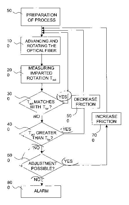
The method for imparting a rotation to . an optical fiber according to the
present
invention will be described with reference to the flow chart in Fig. 1.
In a preliminary step of the method (block 50), certain process parameters may
be set for
the preparation of the process.
First, it may be set a target rotation Ttar which is to be imparted to the
optical fiber, for
example in order to have a desired value of PMD or for other purposes.
For the purposes of the present invention, the term "rotation" denotes the
ratio between
the angular velocity of rotation dO/dt of the optical fibre (where 0 is the
angle -in
radians- of rotation of the optical fibre measured with respect to a fixed
reference point)
and the velocity of fiber advancing, vf. The rotation defined in this way,
multiplied by
the factor 1/27r, can be expressed in turns/m. The rotation as a function of
distance along
the fiber is directly derivable from the corresponding rotation as a function
of time
through the fiber draw velocity (and vice versa). The advancing velocity vf is
normally
constant in the general case, but can be variable.
Advantageously, the target rotation Ttar may be set by properly choosing a
target value
or a target range of values for one or more parameters related to the rotation
imparted.
Advantageously, suitable parameters may be the maximum rotation Tmax,act or
the
CA 02590424 2007-05-31
WO 2006/058551 PCT/EP2004/013713
12
average rotation Tave,aet (in turns/m), which will be defined below. A minimum
value
TMM for the actual average rotation Tave,act may for example be established.
Such
minimum average rotation TMIN may be set, e.g., at about 1 turns/m or at about
1.5
turns/m. In addition or in alternative, a target maximum average rotation TMAX
may be
set, e.g. at about 4 turns/m or at about 3 turns/m.
A further process parameter which may be set is the advancing velocity v f of
the optical
fiber. A still further process parameter which may be set is an initial value
of the
frictional force acting on the optical fibre in order to impart the rotation.
For example an
initial value So may be set for a parameter S of the spinning device, such
parameter
being related to the frictional force acting on. the optical fibre during the
rotation. For
example, this parameter may be the width 8 of the gap defined by two moving
members
which forcibly engage the fiber in order to impart the rotation, as will be
explained
below. Depending on the type of the spinning device used, other parameters may
be
used, as described below.
Depending on the spinning device used, initial values of other parameters of
the
spinning device may be set, such as for example the inversion frequency v and
the
maximum excursion A of the moving member of the spinning device in its
movement
which produces the rotation of the optical fibre. For example, if the spinning
device
comprises a pair of rollers of which at least one can be moved along its
rotation axis, the
maximum excursion A corresponds to the maximum longitudinal relative
displacement
of the at least one roller starting from an equilibrium position. The maximum
excursion
of the moving member of the spinning device determines the value 6maX,aet of
the actual
maximum angle of rotation of the optical fibre.
The value of the inversion frequency v may be selected according to the target
rotation
Ttar (for example the predetermined value TMM and/or TMAx) and the advancing
velocity
vf. A possible range is from 1 Hz to 15 Hz.
On completion of the preliminary step, the process begins (block 100) making
the
optical fiber advancing in a predetermined direction and rotating about its
axis through a
frictional force having the initial value of frictional force set in the
previous step. For
example, a spinning device is made to act on the fiber with the initial value
80 of the
parameter of the spinning device related to the frictional force.
CA 02590424 2007-05-31
WO 2006/058551 PCT/EP2004/013713
13
According to the invention, the actual rotation Tact imparted to the optical
fibre is
measured on line (block 200) during the advancing of the optical fibre. In
this step, the
maximum rotation Tmax,act actually imparted to the optical fibre or,
preferably, the actual
average rotation Tave,act~ may be measured.
According to the invention, the result of this measurement is used to
retroactively
control the actual rotation imparted to the optical fibre, by adjusting the
value of the
frictional force acting on the fiber and responsible of the fiber rotation.
For example, the
value of the parameter S of the spinning device related to the frictional
force is finely
control led.
In detail, the measured actual rotation Tact is compared to the predefined
target rotation
Tta, (block 300). For example, it is checked whether the measured value of the
average
rotation Tave,act is in the predetermined range (block 300). If the measured
actual rotation
Tact is compliant with the predetermined target rotation Ttar (YES output of
block 300),
it is not necessary to vary the actual rotating frictional force. Consequently
the
processing of the fibre may continue without modifications (block 100) and the
previous
steps (blocks 200 and 300) are repeated.
If the measured actual rotation Tact is outside the predetermined
specifications for the
rotation Ta, (NO output of block 300), then a further check is performed
(block 400) to
determine if the actual rotation Tact exceeds the predetermined rotation Ttai.
For
example, a check may be made as to whether Tave,act > TMAX.
If the actual rotation exceeds the predetermined rotation, e.g. Tave,act is
greater than
TMAX (YES output of block 400), the frictional force is decreased, in such a
way that a
certain degree of slippage is allowed and the average actual rotation Tave,act
is decreased
(block 500). The process continues with the rotation of the optical fibre
(block 100) in
the new conditions, and with the repetition of the steps 200, 300 and 400 of
Fig. 1.
If the actual rotation is below the predetermined rotation, e.g. Tave,act is
less than TM1N
(NO output of block 400), preferably a further step (block 600) determines
whether it is
possible to further increase the frictional force exerted onto the fiber. For
exainple, it is
assessed if the frictional force would not reach a limit which may cause the
fiber break
or be mechanically damaged or weakened. If this limit has not been reached,
and
therefore if the frictional force can be increased further (YES output of
block 600), the
CA 02590424 2007-05-31
WO 2006/058551 PCT/EP2004/013713
14
frictional force is increased in such a way as to reduce the slippage and
increase the
actual rotation (block 700), e.g the average actual rotation Ta,,e,act. The
process continues
with the rotation of the fibre (block 100) in the new conditions and with the
repetition of
the steps previously described.
If the operating limit of the frictional force exerted onto the fiber, e.g. by
the spinning
device, has been reached, in other words if the frictional force cannot be
increased
further (NO output of block 600), an alarm signal is generated. The
corresponding
optical fiber is then identified and further processed. The process may be
interrupted or
may continue with the repetition of the steps 100-600 of Fig. 1.
Depending on the. type of spinning device used, variations of the inversion
frequency v
and /or of the maximum excursion A of the moving member of the spinning device
may
also be introduced, in addition to the variations of the frictional force, to
control the
actual rotation Taa, as described in cited application US2002/0178758. '
The adjustment of the friction force (steps 500 and 700) responsively to the
feedback
signal may be performed either by an operator or, more preferably,
automatically.
Figure 2 shows schematically a drawing system 1 for drawing an optical fibre 3
exemplarily using the method of the present invention.
The optical fiber 3 may be any kind of optical fiber, for example single mode,
multimode, dispersion compensating, specialty fiber, etc, made of any suitable
material
such as glass or polymer.
The drawing system 1 comprises a plurality of parts essentially aligned along
a drawing
direction, typically vertical. The drawing system 1 comprises a furnace 4
capable of
heating a preform 2 to beyond its softening point. The preform may be formed
before or
contemporarily to the drawing process by any suitable technique, e.g. OVD, VAD
or
MCVD. The fumace 4 may be of any type capable of producing the controlled
softening
of the preform 2, such as an induction furnace.
The drawing system 1 typically also comprises a pulling device 7 capable of
pulling the
optical fibre 3 downwards at a predetermined velocity vf (called the drawing
velocity)
and a take-up spool 8 on which the optical fibre 3 is wound at the end of the
drawing
process.
CA 02590424 2007-05-31
WO 2006/058551 PCT/EP2004/013713
Advantageously, a coating device 5 for the application of a protective coating
to the
optical fibre 3 is placed along the path of the fiber.
The drawing system 1 also comprises a spinning device 6, preferably positioned
between the coating device 5 and the pulling device 7, apt to impart a
rotation to the
5 optical fibre 3 about its axis 9. The spinning device 6 is characterized by
the fact of
being apt to impart a torsional force to the optical fiber about its axis 9
via a frictional
force. Typically, it is provided with at least one moving member capable of
contactingly
interact with the external surface of the optical fibre 3, so that a
frictional force is
generated between the surface of the moving member and the surface of the
optical fiber
lo (e.g. the fiber coating). The frictional force has at least a component
which is directed
along an axis perpendicular to the fiber axis 9, so as to cause the fiber 3
rotating about
its axis.
The frictional force is typically the product of a compression force which
thrust the fiber
against the spinning device and the coefficient of friction between the
material covering
15 the surface of the spinning device in contact with the optical fiber and
the material
covering the optical fiber surface (e.g. the coating).
The spinning device 6 may be of any kind suitable to apply to the fiber a
torque via a
frictional force. For example, the device may include a rotating member, such
as a
roller, configured so that its rotational axis may tilt with respect to a
predetermined
direction perpendicular to the fiber axis, as described in cited US Patent
5,298,047. In
this configuration, the compression force depends by the tension of the fiber
(called
'drawing tension') and by the deflection of the fiber with respect to the
unperturbed
fiber axis due to the presence of the moving roller. Accordingly, a way to
control the
frictional force, for a given drawing tension, is to finely adjust the
transversal position 6
of the tilting roller with respect to the fiber axis. In order to increase the
frictional force,
it is possible to advance the tilting roller so as to increase the above fiber
deflection.
This increases the compression force of the fiber against the tilting roller
and hence the
frictional force, for given tension and frictional coefficient. Conversely,
withdrawing the
tilting roller in order to reduce the fiber deflection will decrease the
compression force
and hence the frictional force.
CA 02590424 2007-05-31
WO 2006/058551 PCT/EP2004/013713
16
The spinning device 6 may alternatively be, for example, any of the types
described in
the previously cited patent US 6,324,872. In particular, the device 6 may
include a pair
of elements reciprocally facing at the opposite sides of the optical fiber 3
and having
surfaces interacting with the optical fibre. For example the elements may be
rollers, each
of which having its axis perpendicular to the drawing axis 9, and wherein at
least one
roller is moved in a reciprocating way along its own axis, in such a way as to
impart an
alternating spin to the optical fibre 3. For example, the spinning device 6 is
capable of
imparting to the optical fibre 3 an alternating spin with a predetermined
constant
inversion frequency v (in inverse seconds).
In the configuration comprising a pair of elements reciprocally facing at the
opposite
sides of the optical fiber, two cases may be considered for the generation of
the
compression force. In the first case, the two elements rigidly define a gap
therebetween.
For example, the force biasing the two elements one toward the other is much
greater
than the compression force typically acting on the fiber during spinning and a
stop limits
the movement of one element toward the other under the biasing force, so as to
define
the gap. The 'gap' is defined as the distance between the surfaces of the
first and the
second element at the point where the fiber is to be located, in absence of
the fiber 3.
The gap is typically smaller than the diameter of the coated fiber. When the
fiber is
inserted in the gap between the two elements, the two elements substantially
maintain
their original relative distance. The elastic reactions of the fiber coating
and the roller
coating generate the required compression force between the fiber and the
engaging
members. The compression force is hence a function of the width of the gap
between the
first and the second element. Increasing this gap typically result in a
decrease of the
compression force and hence of the frictional force, and viceversa. Further
below, an
example of a spinning device 6 according to this embodiment will be described
in
details with reference to Fig. 3 and 4.
In the second case, the biasing force of the two elements is not counteracted
by a stop
and it directly determines the compression force. For example the two elements
are
biased by a spring and the elastic force of the spring is controlled by way,
e.g., of
controlling the degree of compression, such as varying the position of one end
of the
spring.
CA 02590424 2007-05-31
WO 2006/058551 PCT/EP2004/013713
17
Accordingly, an alternative way to control the frictional force is to adjust
the force
biasing the two members. In this case, in order to increase or decrease the
frictional
force, the biasing force is increased or decreased, respectively. This
increases or
decreases the compression force of the fiber against the roller. Of course,
the present
invention contemplates also hybrid configurations combining the two above
cases,
wherein the control of the compression force may depend by a combination of
adjustment of the gap and of the biasing force.
Various functions may be applied to the rotation of the optical fiber 3 via
the spinning
device 6, such as constant spin rate or variable spin rate functions.
For example, it is preferable to use a pure sinusoid rotation function
resulting in
substantially equal and opposite rotations being introduced onto the fiber for
a given
cycle. Other non-uniform spin functions may be used that are not substantially
sinusoidal and have sufficient variability, e:g., sufficient harmonic content,
to provide a
substantial reduction in PMD for a plurality of beat lengths. For example, a
spin
function can be constructed as a weighted sum of sinusoidal components of
different
frequencies with the number of components and their weights being chosen to
produce
an overall function that achieves PMD reduction. The spin function can also be
randomly generated. In certain embodiments, the spin function is a frequency-
modulated
or an amplitude-modulated sinusoidal function. Preferably, spin functions are
selected
for producing a net twist of zero during drawing.
In the following text it will be exemplarily assumed that the rotation
imparted to the
optical fibre 3 by the spinning device 6 varies according to a sinusoidal law.
It will be
assumed that the optical fibre 3 has, as a result of the action of the device
6, an actual
angle of rotation Oact (measured with respect to a fixed reference point)
expressed by the
relation 9act = Omax,act' sln(27Cvt), where 0max,act is the maximum actual
angle of rotation
and v is the frequency of inversion of the rotation, and that the optical
fibre therefore
undergoes an actual rotation Tact expressed by the relation Tact = Tmax,act '
cos(27cvt),
where Tmax,act =V/Vf ' emax,act is the maximum actual rotation.
The drawing system 1 also comprises a measurement device 10 apt to measure the
actual rotation imparted to the optical fiber 3 in the proximity, and
downstream, of the
neckdown of the preform 2. The measurement may be advantageously placed in any
CA 02590424 2007-05-31
WO 2006/058551 PCT/EP2004/013713
18
position along the path of advancing of the optical fiber 3 where it is needed
to measure
the actual rotation imparted to the fiber 3.
The fiber rotation's measurement device 10 may be of any kind apt to the
purpose, for
example it may comprise a diameter monitoring device capable of measuring the
diameter of the optical fibre 3 (either bare or coated) during its passage and
a processing
unit capable of processing the signal generated by the diameter monitoring
device in
order to generate a fiber rotation measurement, as described in cited Patent
Application
US 2002/0178758 of the same Applicant. The diameter monitor device may
comprise
an optical sensor, for example of the interferometric type, located on the
axis 9. The
diameter monitor is apt to generate an electrical signal responsive of the
diameter of the
optical fibre 3 to be sent to the processing unit. For example, the diameter
monitor
generates an electrical signal via an array of photodiodes receiving the
interference
fringes obtained by directing a laser beam on to the optical fibre. This
signal is sent to
comparator means which generate a number of electrical pulses correlated with
the
fringe pattern. Subsequently, means of counting the pulses supply, according
to the
number of pulses detected, a signal indicating the diameter of the optical
fibre.
Another technique for optically measuring the diameter of an optical fibre
during the
process of its fabrication comprises the steps of transversely illuminating a
portion of
optical fibre with a light beam, measuring the amplitude of the shadow
produced by the
portion of optical fibre in a predetermined angular sector about the optical
fibre, and
determining, from this measurement, the variations of diameter during the
process.
The diameter monitoring device advantageously makes a periodic measurement of
the
diameter of the fibre during the advancing of the optical fibre 3 through it.
The diameter
monitoring device operates at a predetermined measurement frequency, for
example
higher than or equal to 500 Hz. The diameter monitoring device generates a
signal
comprising the sequence of the measured values of diameter. Then, the
processing unit
calculates the normalized power spectrum P(f) of the signal as a function of
frequency f,
which typically comprises a plurality of peaks. Advantageously, the peaks of
the power
spectrum are compared with a preset power threshold PTH (e.g. equal to about
0.1), in
order to eliminate contributions of the spectrum having a power below this
threshold
and, consequently, to reduce the noise. The processing unit then identifies,
among the
CA 02590424 2007-05-31
WO 2006/058551 PCT/EP2004/013713
19
peaks above the threshold PTH, the peak having the maximum frequency fmax. The
processing unit finds, from the value of the maximum frequency fmax, the
maximum
actual rotation Tmax,aa imparted to the optical fibre 3, given by
T = _ f max [turns/m]
(1).
max,act 2 . v
f
For the purpose of accuracy of the measurement and of control of the process,
it is
preferable to calculate the average actual rotation Ta,,e,act imparted to the
optical fibre 3,
which can be determined by:
Tave,act - fave [turns/m] (2),
f
wherein fave is the average frequency of the set of peaks above the threshold
PTH,
provided by the following relation:
Y_ P(fOfk
f - fth<fk<fmax (3),
ave - P(f k
fth<fk fmax )
wherein fth is a cutoff frequency (e.g. 10 Hz) so as to cut some noise near
the zero
frequency.
Each power spectrum P(f) has a large number of peaks, among which the peaks
located
at integer multiples of the inversion frequency v are identified as the
'signal peaks'. The
Applicant believes that signal peaks arise from, e.g., elliptical cross-
section of the fiber,
non elliptical asymmetries (e.g. egg-like cross-section) or phase shift
between diameter
measurement and spin function. In addition, there are numerous undesired peaks
(which
represent a kind of noise), due for example to vibrations and oscillations of
the optical
fibre. The signal peaks therefore represent a subset of the total set of
peaks. If the
number of these undesired peaks is high, the noise associated with them may
make the
measurement of the imparted rotation inaccurate. As described below with
reference to
Fig. 7, the presence of this noise is believed to be an indicator of spinning
conditions not
satisfactory and this noise can conveniently be used to activate a regulation
action based
on that.
Advantageously, the processing unit calculates the average power spectrum
Pa,,e(f) of a
predetermined number of power spectra stored in the processing unit. The
average of a
CA 02590424 2007-05-31
WO 2006/058551 PCT/EP2004/013713
plurality of spectra acquired in a time interval in which the frequency of
inversion of the
rotation is essentially constant has a number of undesired peaks (and,
therefore, a
quantity of noise) which is much smaller than the individual spectra. The
processing
unit preferably calculates a'quality' of the resulting average spectrum
Pave(f), which is
5 defined as the ratio of the number of signal peaks Np (spaced of a quantity
equal to
integer multiples of the inversion frequency v) and the total number of peaks
NP,t
present in the resulting average spectrum.
A control unit 12 is provided to the processing system 1 in order to control
the operation
of the spinning device 6 according to the control algorithm described with
reference to
10 Fig. 1. The control unit 12 may also advantageously carry out other
functions related to
the process. For example it may include the processing unit which elaborate
the signal
generated by the diameter monitoring, as described above, and/or execute a
software
algorithm incorporating a spin function and/or control other aspects of the
process such
as controlling the drawing velocity (by altering the speed of the pulling and
take-up
15 devices 7 and 8), or controlling the heat of the heat source 4, for example
responsively
to diameter measurements received from the diameter measurement device.
The control unit 12 is advantageously configured to receive a first signal S,
from the
rotation measurement device 10, store this signal and process it, as described
below. It is
also configured to generate a second signal S2, which may be sent to the
spinning device
20 6, and, optionally, a third signal S3, which may be sent to a monitor 16.
The operation of the drawing system I according to the present invention will
now be
described with reference to both Fig. 1 and Fig. 2.
Target values or target range of Tave,act and/or Tmax,act are predetermined
before the start
of the process. Such values or range represent the actual rotation which is to
be imparted
to the optical fibre in such a way as to provide the fiber with the desired
transmission
characteristics, such as the PMD. In the latter case, when optical signals are
transmitted
into the fiber, the exchanges of power between the propagation modes are such
that the
effects of the imperfections and irregularities of the fibre are rendered
uniform in a
length of the fibre equal to at least the beat length. Thus it is possible to
reduce
significantly the negative effects caused by the asymmetric stress conditions
and by the
imperfections of shape intrinsically present in the fibre. To achieve this
object, it is
CA 02590424 2007-05-31
WO 2006/058551 PCT/EP2004/013713
21
advantageous to impart to the optical fibre a spin such that an average
rotation Tave,act is
induced above TM[N=1 turn/m or 1.5 turns/m. Optionally, a finite value of TMAX
may be
predefined, even thought from the point of view of fiber performance, the
higher Tave,acb
the better the results (for example the PMD tends to decrease for increasing
value of
Tave,act). Nevertheless, an excessive rotation may subject the fiber to
excessive
mechanical stress and may cause the fiber to oscillate, thus arousing a noisy
measure.
For example, good values for TMAx may be 4 turns/m or 3 turns/m.
The drawing velocity vf for a single-mode fibre is typically set in the range
from 5 m/s
to 30 m/s.
In the preliminary step (block 50 of Fig. 1) the drawing system 1 is prepared
by first
advancing the preform 2 inside the furnace 4, which has previously been heated
to a
temperature higher than the softening point. The lower portion of the preform
2 is
melted, with consequent generation of a drop of melted material. This drop is
elongated
downwards under the action of the force of gravity, drawing with it additional
melted
material in such a way as to form a threadlike element of molten material
which is
cooled progressively. This threadlike element is made to pass through the
spinning
monitoring device 10 (which typically includes a diameter monitoring device),
the
coating device 5, the spinning device 6 and the pulling device 7, and a few
turns of it are
wound on to the take-up spool 8.
Afterwards (block 100 of Fig. 1), the optical fiber is advanced in a
predetermined
direction, for example with the activation of the pulling device 7. The
pulling device 7
pulls the optical fibre 3 downwards at a velocity which progressively rump-up
to the
predetermined drawing velocity vf, causing its continuous formation from a
lower neck-
shaped (called neck-down) portion 2' of the preform 2. The coating device 5
applies the
protective coating to the optical fibre 3 which passes through it.
The spinning device 6 is made to act on the fiber 3 with the initial value of
the frictional
force set at the beginning of the process. For example, the initial value 60
of the
parameter of the spinning device 6 is communicated to the spinning device 6 by
the
control unit 12 by means of a second signal S2.
The equipment 10 is used to measure (block 200 of Fig. 1) the actual rotation
Tact
imparted to the optical fibre just below the neck-down region 2', i.e. the
actual imparted
CA 02590424 2007-05-31
WO 2006/058551 PCT/EP2004/013713
22
spin. Such measurement is obtained at the beginning of the drawing process and
during
the process itself at a rate of at least one detection per one thousand meter
of drawn
fiber, preferably per one hundred meter. The measured actual rotation may
deviate from
the predetermined rotation Ttan as previously discussed.
The rotation measurement device 10 generates a first signal Sl indicative of
the actual
rotation imparted to the fiber and sends it to the control unit 12.
According to the invention, the result of this measurement is used to
retroactively
control the actual rotation imparted to the optical fibre, by adjusting the
value S of the
parameter of the spinning device related -to the frictional force.
The control unit 12 compares the measured actual rotation Tact with the
predetermined
reference rotation Ttar (block 300). For example, the unit 12 checks whether
the
measured value Tave,act is above the predetermined value TMrN and/or below the
predetermined value TMAx. No feedback is fed to the spinning device 6 if the
actual
rotation comply with the predetermined specification (YES output of block
300).
If the actual rotation exceed the predetermined rotation, e.g. Tave,act is
greater than TMAX
(YES output of block 400), the control unit 12 in one embodiment generates and
sends
to the spinning device 6, by means of the second signal S2, the control
command to
decrease the frictional force, in such a way that the average actual rotation
Tave,act may be
decreased (block 500 of Fig. 1). The drawing process continues with the
rotation of the
optical fibre (block 100) in the new conditions and with the repetition of the
steps of
advancing the fiber, measuring the actual rotation and determining if the
actual rotation
is in specifications. In another embodiment the control unit 12 generates a
third signal
S3 to be sent to the monitor 16 so as to be visible by an operator, which may
perform the
operation of reducing the frictional force of the spinning device 6.
If the actual rotation is below the predetermined rotation, e.g. Tave,act is
less than TM[N
(NO output of block 400), the control unit 12 makes a further optional check
(block
600) to determine whether the frictional force has not reached a limit which
may cause
the fiber break or become mechanically weak. If this limit has not been
reached (YES
output of block 600), the control unit 12 in one embodiment sends to the
spinning
device 6, by means of the second signal S2, the command to increase the
frictional force
in such a way as to increase, e.g., the average actual rotation Tave,act
(block 700). The
CA 02590424 2007-05-31
WO 2006/058551 PCT/EP2004/013713
23
process continues with the spinning of the fibre (block 100) in the new
conditions and
with the repetition of the steps previously described. In another embodiment,
the control
unit 12 may generate the third signal S3 to be sent to the monitor 16 so as to
be visible
by an operator, which may perform the above operation of increasing the
frictional force
of the spinning device 6.
Advantageously, the fiber corresponding to an actual rotation measurement
outside the
predetermined specifications is alarmed (e.g. identified by coarse winding).
If the operating limit of the frictional force exerted by the spinning device
6 has been
reached (NO output of block 600), the control unit 12 generates an alarm
signal, for
example via the third signal S3 to be sent to the monitor 16. The
corresponding optical
fiber is then identified and further processed.
Depending on the type of spinning device used, variations of the inversion
frequency v
and /or of the maximum excursion A of the moving member of the spinning device
6
may also be introduced to control the actual. rotation Tact, as described in
cited
application US2002/0178758.
An exemplary embodiment of the spinning device 6 particularly suitable for the
method
and system of the present invention will now be described in details, with
reference to
figure 3 (side view) and Fig. 4 (top view). The same reference numerals are
used for
same elements.
The spinning device 6 comprises a first and a second roller 102 and 103 with
cylindrical
shape rotating about the respective rotation axis 104 and 105. The rollers 102
and 103
may be covered with a resilient material. The two rollers engage in opposite
sides the
optical fiber 3 while drawing. The axes 104 and 105 are parallel with each
other and
perpendicular to the axis of the fiber 3. The roller 103 is mounted on a
carriage 107 and
is held by two elements 111 and 112 in such a way that it can freely rotate
about its axis
105. The roller 102 is mounted on a carriage 106 and is held by a first
element 110 of
Fig. 3 and a similar second element (not shown) on the other side of the
roller, in such a
way that it can freely rotate about its axis 104. The camage 106 slides over a
support
120, which is in turn firmly connected to the drawing tower. Analogously, the
carriage
107 slides over a support 121, firmly connected to the drawing tower. The
relative
CA 02590424 2007-05-31
WO 2006/058551 PCT/EP2004/013713
24
sliding movements of the two' carriages 106 and 107 are substantially parallel
each
other, and parallel to the axis 104 and 105 of the two rollers 102 and 103.
The element 110 is connected to the carriage 106 through a pivotable joint 115
which
acts as a fulcrum to tilt the roller 102 respect to roller 103. The double
arrows curve in
Fig. 3 illustrates the tilt movement of the element 110. The element 110 has a
C-shaped
protrusion 113 protruding from some point between the fulcrum 115 and the axis
104 of
the roller 102. On the upper side of the element 113 a wheel 130 is mounted so
that it
can freely rotate around its axis 132, substantially parallel to the axis of
the fiber 101.
Similarly, the above-mentioned second element, positioned on the other side of
the
roller 102 with respect to the element 110, is mounted on the carriage 106
through a
rotable hinge. Such an element has a C-shaped protrusion 114 similar to
protrusion 113.
On the upper side of the element 114 a wheel 131 is mounted so that it can
freely rotate
around its axis 134, substantially parallel to the axis of the fiber 101. The
two wheels
130 and 131 can freely rotate on an element 140, over which they are biased by
the
effect of the spring 141, compressed between the carriage 106 and the lower
arm of
protrusion 113. Therefore, when the carriage 106 slides over the support 120,
the two
wheels 130 and 131 rotate onto the flat surface of 140. The element 140 can
slide on a
group of rails 145, 146, 147, firmly connected to the vertical upright 150,
mounted on
the support 121. The position of the element 140 with respect to the axis of
the fiber 3 is
driven by two piezoelectric elements 151, which are electronically driven and
monitored, in such a way their extension is determined within 1 micron.
The elements 110, 113 and 130 define a first support carrying the first roller
102. The
elements 121, 107, 111, 150, 145 and 146 define a second support carrying the
second
roller 103. The spring 141 acting on the first support biases the first
support towards the
element 140 and the force of biasing is set greater than the compression force
typically
involved during fiber rotation, so that, when the fiber is inserted between
the two rollers,
they substantially maintain the gap unchanged under the action of the biasing
force.
Depending on the position of the element 140, actuated by the piezoelectric
elements
151 which act between said first and second support against the action of the
spring 141,
the gap between the two rollers 102 and 103 can be varied and maintained with
high
accuracy. The compression force is essentially determined, for given operating
CA 02590424 2007-05-31
WO 2006/058551 PCT/EP2004/013713
conditions, by the gap between the two rollers 102 and 103, as previously
defined. The
biasing force of the spring 141 fixes the maximum force of compression which
may act
on the fiber 3 by the two rollers 102 and 103 for a sufficiently small gap.
It is thus possible to control the frictional force acting on the optical
fibre 3 during the
5 rotation by controlling the value S of the gap of the spinning device 6 of
Fig. 3 and 4.
In an alternative configuration, the actuator 151 and the spring 141 are
replaced by a
stepping motor which control the position of the first roller 102 with respect
to the
second roller 103, for example by driving a micrometer screw acting on the
first roller
102. In a still further configuration, the actuator may act on the spring 141
in order to
10 control the biasing force between the two rollers, said biasing force being
related to the
compression force acting on the fiber 3, as described further above (in this
case the gap,
as defined above, is vanishing).
The spinning device 6 is driven to impart a pure sinusoid spinning function.
Accordingly, the movement of the two carriages 106 and 107 is substantially a
sinusoid
15 as driven by a crankshaft 160 (shown in Fig. 4) rotating around its axis
161, and
connected to the carriages through two elements 162 and 163. Such a movement
will
rotate the fiber 3 in a corresponding sinusoidal way. The shape of the
crankshaft 160
determines the fixed amplitude A of the sinusoid, while the angular speed
determines
the inversion frequency v.
20 The experimental results of the processing of a set of 68 glass preforms
(of nearly 300
km each) which have been drawn imparting a rotation according to the method of
the
present invention, will be illustrated below.
The preforms, having respective refractive index profile so as to result in
conventional
single mode optical fiber with a diameter of approximately 125 m and low
25 birefringence, were obtained by outside vapor deposition (OVD) process.
A vertical drawing system similar to the one described with reference to Fig.
2 was used
to draw the set of preforms. The predetermined minimum average rotation was
set at
TMIN=1.5 tums/m. No maximum average rotation TMAX was set. Drawing velocity vf
was set at 18 m/s.
The spinning device 6 was of the kind described above with reference to Fig. 3
and 4,
wherein the inversion frequency v of the two rollers 102 and 103 was set at
3.7 Hz and
CA 02590424 2007-05-31
WO 2006/058551 PCT/EP2004/013713
26
maintained constant during the process. The excursion (amplitude A) of the
transversal
movement of the two rollers was about 5 mm (that is one roller has a position
with
respect to the central position expressed by x=A cos(27tvt) and the other by
x= -A
cos(27rvt)).
A diameter monitoring system was used to measure the actual average spin
imparted to
the fiber via a numerical processing of the diameter measurement signal taken
below the
neck-down region of the preform, as described above. The actual average spin
is
obtained from a spectrum which is the average of four diameter signal spectra.
The
actual average spin is obtained at the beginning of the drawing process of
each preform
and during the process itself at a rate of one value every about 300-400 m of
drawn fiber
(each individual spectrum is taken at a rate of one every about 100 m).
When the target drawing velocity was achieved, after ramp-up, the
piezoelectric
elements 151 have been driven to get an initial average rotation of at least 2
turns/meter
and no more than 3 turns/meter. The on-line measurements of spin have been
used to
check whether the level of the average spin was maintained higher than 1.5
turns/m
throughout the whole drawing process. Such information has been used to
retroactively
tune the gap of the spinner device as needed in order to get the target
minimum level of
spin. In this way it was possible to guarantee that the average spin always
remained
above 1.5 turns/m along the whole process of each perform.
The result of the PMD measurements on the fiber production from the 68
preforms
drawn according to the above, with the wavelength scanning method (Fixed
Analyser
Measurement method, IEC 60793-1-48 (Method A)) over a sample of bobbins each
long
about 5 to 20 km and wound at zero-tension, can be summarized as follows:
Average PMD = 0.028 ps/Am
Standard deviation PMD= 0.006 ps/Am
PLDV = 0.033 ps/Am
This result shows the advantage of the methodology of the present invention
with
respect to a production in the same conditions but without spinning monitoring
and
feedback on the frictional force, which can be summarized as follows:
Average PMD= 0.040 ps/Am
Standard deviation PMD= 0.020 ps/Am
CA 02590424 2007-05-31
WO 2006/058551 PCT/EP2004/013713
27
PLDV = 0.064 ps/Am
The PMD Link Design Value (PLDV) is obtained according to document IEC
86C/265/CD entitled "IEC 61282-3: Guidelines for the calculation of PMD in
fibre
optic systems", paragraph 3.1.1.1 and 3.1.2.1. That is, from PMD measurements
on a
random sample of the whole production of fiber, a distribution of foreseen PMD
values
for a link of 24 fibers is obtained by Montecarlo simulation. The PLDV is
defined such
as 99.9% of the data stay below the PLDV.
It is evident the advantage in terms of better average PMD. A further
advantage of the
present invention, when applied to fiber drawing, is that, since the
continuous
monitoring and feedback may be used to guarantee a narrow distribution of the
actual
average rotation of the fiber along the whole drawing process, it is also
expected a
narrow distribution of the corresponding PMD. This is confirmed by the
comparison of
the PMD standard deviation values shown above. This in tum results in lower
PLDV
and, more important, in the possibility to reduce the number of PMD
measurements,
which are complex and time consuming.
The Applicant has verified that the method of the present invention is
advantageously
performed at least once (measure of actual spin, comparison with target spin
and, in
case, adjustment of the frictional force) in the first quarter of the total
duration of the
drawing process, calculated from the instant the drawing process has reached
its regime
conditions (e.g. the pre-set drawing velocity). Preferably, at least one
additional control
according to the method of the present invention is done after the first
quarter. For
example, at least one additional control at about half the process time. More
preferably,
the method of the present invention is repeated at least several times during
the process,
for example once every period equal to about 50% or 25% of the total drawing
duration,
preferably at regular intervals such as once every ten minutes.
With reference to Fig 5, it will now be conceptually illustrated the principle
of operation
of the method of the present invention.
Fig. 5 shows the measured average rotation as a function of time in arbitrary
units (a.u.)
for an optical fiber drawn according to the above.
The alarm threshold for the average rotation (TMN) is exemplarily set at 1.65
turns/m
and a feedback on the gap of the spinning device 6 of Figs. 3 and 4 was
performed
CA 02590424 2007-05-31
WO 2006/058551 PCT/EP2004/013713
28
manually when this threshold was crossed for a significant period of time. As
shown in
Fig. 5 by the two arrows in proximity of the time of 6000 a.u., in
correspondence of a
time interval of about 300 a.u., which corresponds to a span length of fiber
of about 5
km, the actual average rotation has been below threshold. Before 6000 a.u.,
the average
rotation has been below the threshold for negligible time intervals. Thus, the
piezoelectric elements 151 of Figs. 3 and 4 have been driven in order to
reduce the gap
of the spinning device 6 of Figs. 3 and 4 of about 10 m. The average rotation
promptly
raised at an acceptable level. It is observed that for the data shown in Fig.
5, the
feedback was not optimized, so that the decrease of the average rotation at
about 13000
a.u. was not counterbalanced.
It is of course possible to configure the feedback control loop function in
order to timely
react to the variation in the measured average rotation.
As a comparative example, Fig. 6 shows a plot similar to the one shown in Fig.
5 with
the exception that no feedback was done during the drawing process. The
average
rotation progressively declines down to values below the specification range
near the
end of the drawing process. It is believed that the coefficient of friction
has
progressively decreased. An active feedback according to the present invention
is able to
correct for it by gradually reducing the gap between the first and the second
roller 102
and 103 in order to increase the compression force.
Fig. 7 shows the average rotation (upper curve, left scale) and the spectrum
quality
(lower curve, right scale) during a drawing process (time arbitrary units) as
exemplarily
described above. The spectrum quality (of an average power spectrum obtained
by
averaging four power spectra) is defined according to the above. Again, the
alarm
threshold for the average rotation (TMrN) is exemplarily set at 1.65 turns/m
and the
feedback on the gap of the spinning device 6 of Figs. 3 and 4 was performed
manually.
Up to 6000 arbitrary units of time, the measured average rotation rapidly
fluctuated in a
large range of variation (between about 1 to 3 turns/m). Most important, the
measure of
the average rotation was not reliable because the power spectrum quality was
low (about
0.25, in any case below 0.5). It is believed that the optical fiber 101,
probably due to a
gap between the two rollers 102 and 103 larger than the optimal and thus a
compressive
force acting on the fiber not sufficient, were not firmly engaged between the
two rollers.
CA 02590424 2007-05-31
WO 2006/058551 PCT/EP2004/013713
29
The optical fiber is thought to irregularly slip and/or jump on the surface of
the rollers
102 and 103, causing both a fluctuating average rotation and an irregular
oscillation of
the optical fiber in the direction transverse to the fiber axis. The latter
may have given
rise to a noisy power spectrum.
Near 6000 arbitrary units, the two rollers 102 and 103 were brought closer to
each other
reducing the gap of about 40 m. The power spectrum improved considerably
(quality
greater than 0.5) and the measured average rotation showed a steady value
complying
with the specification (about 1.8 turns/m).
Accordingly, the Applicant has found that the power spectrum quality, which is
related
to the actual fiber rotation, is a good indicator of the correct working of
the spinning
device 6 and may be used to retroactively control it, in addition or
alternatively to a
specific spinning parameter such as the average rotation.
In an embodiment of the invention, the method of the present invention is
aimed to
optimize the compression force acting on the optical fiber in function of the
instantaneous coefficient of friction. Referring again to Fig. 1, when the
output of step
represented by block 300 is YES (i.e. the imparted rotation is in the expected
range), it
is possible to configure the control unit 12 so as to decrease the compression
force. In
this way the method seeks the minimum compression force which is sufficient to
get the
predetennined rotation, in function of the instantaneous coefficient of
friction. The
advantage of this solution is that the fiber is subjected to a mechanical
stress (e.g.
squeezing) as minimum as possible, thus improving its mechanical properties.
In addition to the application described with respect to a drawing process,
the method
according to the present invention can be applied to other processes in which
it is
desired to guarantee a target actual rotation imparted to an optical fibre
while the fibre is
made to advance in a predetermined direction.