Note : Les descriptions sont présentées dans la langue officielle dans laquelle elles ont été soumises.
CA 02595537 2007-07-20
WO 2005/117663 PCT/US2005/018219
STATIONARY CHILD EXERCISE APPARATUS WITH BOUNCING PAD
BACKGROUND OF THE INVENTION
Stationary exercise apparatuses are used to assist children in the
development of the muscles and coordination needed for walking. A typical
stationary child exercise apparatus includes a seat portion that is positioned
in the
center of the apparatus and is at least partially surrounded by an annular-
shaped
activity tray. The activity tray includes toys that entertain the child. The
stationary
apparatus is held in a stationary position by legs that extend downwardly from
the
activity tray. In most stationary exercise apparatuses, the seat portion can
rotate
360 , independently of the activity tray, about an axis of rotation that is
defined by
the center of the seat portion.
U.S. Patent No. 6,299,247 to Meeker ("the '247 Patent") discloses a child
exerciser/rocker that includes a bowl-shaped base adapted to rock in any
direction,
three equally spaced towers extending upwardly from the upper periphery of the
base, a circular tray that is positioned on top of the towers, and a seat for
receiving
a child that is rotatably mounted in the center of the tray. The towers
include
springs to allow a child positioned in the seat to bounce with respect to the
base,
and the heights of the towers are adjustable. However, the base itself does
not
bounce and the vertical motion provided by the springs in the towers is felt
by the
child through the seat, and not through the child's legs. In addition, the
seat and
circular tray move together when the child bounces in the rocker, which may
cause
food or drinks on the tray to spill.
U.S. Patent 3,195,890 to Salls ("the '890 Patent") discloses a resilient
action jumping toy that includes an upstanding, cylindrical-shaped framework
with
a foot-engageable platform at the bottom of the framework. Between the
platform
and the floor are compressible elastic energy storing means, such as
compression
springs, that provide oscillatory movement to the platform when a child
standing
on the platform jumps up and down. However, because the jumping toy does not
have a seat for supporting a child over the foot engageable platform, the toy
is
unsuitable for small children that have not yet developed the muscles and
coordination needed for standing. In addition, the compressive elastic energy
CA 02595537 2007-07-20
WO 2005/117663 PCT/US2005/018219
storing means cannot be adjusted to increase or decrease the amount of
oscillatory
movement of the platform.
U.S. Patent No. 4,900,011 to Nolet ("the '011 Patent") discloses an
exerciser and playpen structure that has a trampoline like bottom surface. A
child
standing on the resilient surface can grip an upper frame of the structure
with its
hands and move its legs up and down to take advantage of the rebounding effect
of
the resilient surface. However, like the jumping toy of the '890 Patent, this
structure does not include a seat for supporting a child that has not yet
developed
the muscles and coordination needed for standing, and the tension of the
resilient
surface cannot be increased or decreased.
Therefore, an unsatisfied need in the art exists for a stationary child
exercise apparatus that is able to support a child over a resilient surface
while the
child develops the muscles and coordination needed for standing and walking
and
allows for the adjustment of a tension element of the resilient surface.
BRIEF SUMMARY OF THE INVENTION
The invention is directed to a stationary exercise and activity apparatus for
providing cognitive development activities for small children and exercise
functionality. In one embodiment, the apparatus includes an activity table
adapted
for receiving one or more children's activity items, one or more legs
supported on
a floor, a seat supported by the legs, and a resilient support surface
suspended
generally horizontally from at least one of the legs. The seat has a pair of
leg
openings that allow the child to touch the resilient support surface with its
legs, and
the resilient support surface has a resiliency that allows the child to bounce
vertically by pushing its legs downwardly against the resilient support
surface.
Furthermore, the distance between the resilient support surface and the seat
can be
increased or decreased to account for the height of the child placed within
the
apparatus by moving the resilient support surface, and a tension element of
the
resilient support surface can be adjusted to account for the strength of the
child.
In one embodiment, the legs extend downwardly and outwardly toward the
floor. When the resilient support surface is moved closer to the seat, the
tension
element of the resilient support surface is decreased, resulting in a child
having to
2
CA 02595537 2007-07-20
WO 2005/117663 PCT/US2005/018219
apply less force with its legs to achieve a bouncing motion. When the
resilient
support surface is moved closer to the floor, the tension element is
increased,
resulting in the child having to apply more force with its legs to achieve a
bouncing
motion. This feature advantageously accounts for the gradual development of
the
child's muscles and coordination by automatically adjusting the tension
element of
the resilient support surface based on the size of the child.
BRIEF DESCRIPTION OF THE DRAWINGS
Reference will now be made to the accompanying drawings, which are not
necessarily drawn to scale, and wherein:
Figure 1 shows a perspective view of a stationary child exercise apparatus
according to one embodiment of the invention;
Figure 2 shows a perspective view of a stationary child exercise apparatus
according to another embodiment of the invention;
Figure 3 shows a perspective view of a stationary child exercise apparatus
according to another embodiment of the invention;
Figure 4 shows a top view of a stationary child exercise apparatus
according to one embodiment of the invention;
Figure 5 shows a perspective view of a seat carrier ring according to one
embodiment of the invention;
Figure 6 shows a cross-sectional view of a seat carrier ring and a seat
support ring according to one embodiment of the invention;
Figure 7 shows a perspective view of an activity table and a seat support
ring according to one embodiment of the invention;
Figure 8 shows a cross-sectional view of an activity table and a seat support
ring according to one embodiment of the invention;
Figure 9A shows a perspective view of a seat support ring and a leg
according to one embodiment of the invention;
3
CA 02595537 2007-07-20
WO 2005/117663 PCT/US2005/018219
Figure 9B shows a perspective view of a seat support ring and a leg
according to one embodiment of the invention;
Figure 10 shows a perspective view of a table and a leg according to one
embodiment of the invention.
Figure 11 shows a perspective view of a seat carrier ring according to one
embodiment of the invention;
Figure 12 shows a perspective view of a wheel according to one
embodiment of the invention;
Figure 13 shows a perspective view of a sling according to one
embodiment of the invention;
Figure 14 shows a top view of a resilient support surface according to one
embodiment of the invention;
Figure 15 shows a perspective view of a resilient support surface according
to one embodiment of the invention;
Figure 16 shows a perspective view of a mounting portion in a leg
according to one embodiment of the invention;
Figure 17 shows a perspective view of a mounting portion in a leg
according to one embodiment of the invention;
Figure 18 shows a perspective view of a mounting portion in a leg
according to one embodiment of the invention;
Figure 19 shows a perspective view of a mounting portion in a leg
according to one embodiment of the invention;
Figure 20 shows a perspective view of a mounting portion in a leg
according to one embodiment of the invention;
Figure 21A shows a perspective view of a mounting portion in a leg
according to one embodiment of the invention;
4
CA 02595537 2007-07-20
WO 2005/117663 PCT/US2005/018219
Figure 21B shows a perspective view of a mounting portion in a leg
according to one embodiment of the invention;
Figure 21 C shows a perspective view of a pin according to one
embodiment of the invention;
Figure 22 shows a perspective view of a mounting portion in a leg
according to one embodiment of the invention;
Figure 23 shows a perspective view of a mounting portion in a leg
according to one embodiment of the invention; -
Figure 24A shows a perspective view of a mounting portion in a leg
according to one embodiment of the invention;
Figure 24B shows a perspective view of a pin according to one
embodiment of the invention;
Figure 25 shows a perspective view of a mounting portion in a leg
according to one embodiment of the invention; and
Figure 26 shows a perspective view of a mounting portion in a leg
according to one embodiment of the invention.
DETAILED DESCRIPTION OF THE INVENTION
The present invention now will be described more fully hereinafter with
reference to the accompanying drawings, in which embodiments of the invention
are shown. This invention may, however, be embodied in many different forms
and should not be construed as limited to the embodiments set forth herein;
rather,
these embodiments are provided so that this disclosure will be thorough and
complete, and will fully convey the scope of the invention to those skilled in
the
art. Like numbers refer to like elements throughout.
Generally, the present invention is directed to a children's stationary
exercise apparatus. In one embodiment, the apparatus includes a seat, one or
more
legs depending downwardly towards a floor and supporting the seat, an activity
table, and a resilient support surface, or bouncing pad. The seat is mounted
in the
5
CA 02595537 2007-07-20
WO 2005/117663 PCT/US2005/018219
center ot the activity table and can be configured to rotate 360 about its
own axis
of rotation. The legs extend downwardly and outwardly from the seat, and the
resilient support surface is suspended horizontally from the legs and is
positioned
vertically between the seat and the floor. A child positioned within the
apparatus
pushes its legs against the resilient support surface to achieve an up and
down
bouncing motion. This bouncing motion assists in the development of the
muscles
and coordination needed for standing and walking. Furthermore, the distance
between the resilient support surface and the seat can be increased or
decreased to
account for the height of the child by lowering or raising the resilient
support
surface, and, in one embodiment, a tension element of the resilient support
surface
is increased as the distance between the seat and the resilient support
surface is
increased, which provides more resistance for the child's legs.
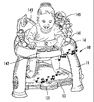
As shown in Figure 1, one embodiment of the invention is a children's
exercise apparatus 10 for providing exercise functionality for a small child.
The
apparatus 10 includes one or more legs 11 supported on a floor, a seat 12
supported
by the legs 11 and structured to support the child while allowing the child's
legs to
extend downwardly below the seat 12, and a resilient support surface 13 that
is
suspended generally horizontally from the legs 11 and positioned vertically
between the seat 12 and the floor. The resilient support surface 13 has a
resiliency
that is adapted for allowing the child to bounce vertically by pushing its
legs
downwardly against the resilient support surface 13. As shown in Figure 2, a
further embodiment of the apparatus 10 includes an activity table 14 that
includes
an upper surface 141 for supporting activity items 142, such as toys, teething
rings,
and interactive learning modules. Figure 3 illustrates another embodiment of
an
activity table 14 that includes toy bars 143 on the upper surface 141 of the
activity
table 14 on which activity items may be mounted. Further, as shown in Figure
4,
the seat 12 defines a pair of leg openings 121 that allow the child to touch
the
resilient support surface 13 with its legs.
The various embodiments of the elements of the apparatus 10 are discussed
in more detail below. However, these embodiments are exemplary and should not
limit the scope of the invention, and one or more features from one embodiment
could be combined with features from other embodiments.
6
CA 02595537 2007-07-20
WO 2005/117663 PCT/US2005/018219
Seat
The seat 12, according to one embodiment, includes a seat carrier ring 201
and a seat support ring 211. As shown schematically in Figure 6, an annular
horizontal surface 202 on the seat carrier ring 201 is mounted adjacent to and
vertically supported by an annular horizontal surface 212 of the seat support
ring
211, and a central axis B of the seat support ring 211 is coaxial with a
central axis
A of the seat carrier ring 211. Thus, the seat carrier ring 201 can rotate 360
about
the axis A, independently of the seat support ring 211.
As shown in Figures 6 through 8, one embodiment of the seat support ring
211 has a central vertical axis B and includes an inner wall 213, an outer
wall 214,
and an annular horizontal engagement surface 212 positioned between the inner
213 and outer walls 214. The width of the annular horizontal engagement
surface
212 is wide enough to provide vertical support for a seat carrier ring 201
mounted
adjacent to the horizontal engagement surface 212. As will be discussed below
in
more detail in the section below entitled "Activity Table," one embodiment of
the
seat support ring 211 is integrally formed with an activity table 14, as shown
in
Figure 7, and one embodiment of the seat support ring 211 is separate from the
activity table 14, as shown in Figure 8.
As mentioned above, the seat carrier ring 201 has a central vertical axis A
and includes an inner wall 203, an outer wall 204, and a horizontal annular
surface
202 positioned between the inner 203 and outer walls 204. In one embodiment,
shown in Figures 5 and 11, the horizontal annular surface 202 of the seat
carrier
ring 201 includes a plurality of ribs 205 positioned between the inner wall
203 and
outer wall 204. Each of the ribs 205 defines a mounting portion 206 that
receives a
roller 32. According to one embodiment, as shown in Figure 11, the mounting
portion 206 has a C-shaped cross section and defines an aperture 217 having
the
approximate diameter of an axis 31 of a wheel 32, shown in Figure 12, and an
opening 218 into the aperture 217 that has a width slightly less than the
diameter of
the axis 31 of the wheel 32. Thus, the axis 31 of the wheel 32 can be snapped
into
the C-shaped mounting portion 206. When the seat carrier ring 201 is
positioned
within the seat support ring 211, outer surfaces 33 of the wheels 32 engage
the
horizontal surface 212 of the seat support ring 211, and the wheels 32 rotate
about
7
CA 02595537 2007-07-20
WO 2005/117663 PCT/US2005/018219
their axes 31 to facilitate the rotation of the seat carrier ring 201 relative
to the seat
support ring 211.
In a further embodiment, as shown in Figure 5, the inner wall 203 of the
seat carrier ring 201 extends below the lower surface 202 and includes one or
more
cantilevered latches 207. The cantilevered latches 207 include a horizontal
shelf
208 that extends away from the central axis A of the seat carrier ring 201.
The
latches 207 are configured to deflect slightly inwardly towards the central
axis A
when the seat carrier ring 201 is inserted into the seat support ring 211. As
shown
in Figure 6, when the seat carrier ring 201 is fully inserted into the seat
support
ring 211, the horizontal shelves 208 of the latches 207 are positioned below
the
inner wall 213 of the seat support ring 211 such that each horizontal shelf
208 is
adjacent the bottom edge of the inner wall 213 of the seat support ring 211,
preventing the seat carrier ring 201 from being unintentionally removed from
the
seat support ring 211. To remove the seat carrier ring 201 from the seat
support
ring 211, the latches 207 are pushed inwardly as the seat carrier ring 201 is
urged
upwardly.
Figure 13 illustrates one embodiment of a fabric sling 230 that attaches to
the seat carrier ring 201. Once attached to the seat carrier ring 201, the
child can
sit on the sling 230. In one embodiment, the sling 230 includes a pair of leg
openings 221 that allow the child to touch the floor with its legs. In
addition, the
sling 230 includes loops 231 along a top portion 232 of the sling 230 to
engage
tabs 209, shown in Figure 5, that extend downwardly from the outer wall 204 of
the seat carrier ring 201. To secure the fabric sling 230 to the seat carrier
ring 201,
the sling 230 is positioned through the center of the seat carrier ring 230,
the top
portion 232 of the sling 230 is wrapped over the outer wall 204 of the seat
carrier
ring 201, and the loops 231 are hooked over the tabs 209. Alternatively,
snaps,
buttons, clips, or other suitable fasteners may be used to secure the sling
230 to the
seat carrier ring 201.
Resilient Support Surface
As discussed above in relation to Figures 1 through 3, the exercise
apparatus 10 includes a resilient support surface 13 that is suspended
generally
8
CA 02595537 2007-07-20
WO 2005/117663 PCT/US2005/018219
horizontally from the legs 11 and positioned vertically between the seat 12
and the
floor. The resilient support surface 13 has a resiliency that allows the child
to
bounce vertically by pushing its legs downwardly against the resilient support
surface 13. The resiliency may be provided by the support surface 13, by
connectors that mount the support surface 13 adjacent to the mounting portions
112 of the legs 11, or both.
When the resiliency is provided by the support surface 13, at least in part,
the support surface 13 is formed using various types of materials that provide
resiliency. For example, in one embodiment, the support surface 13 is formed
of a
flexible material, such as nylon, natural or synthetic elastomers, rubber,
fabric
mesh, woven polypropylene, or fabric. In another embodiment, a center portion
132 of the support surface 13 is a flexible material and at least a portion of
an outer
periphery 133 of the support surface 13 is a rigid material, such as plastic,
metal, or
wood. And, in yet another embodiment, the center portion 132 is a rigid
material
and at least a portion of the outer periphery 133 is a flexible material.
In an embodiment in which the resiliency is provided at least in part by the
connector, the support surface 13 may be formed of flexible material, rigid
material, or a combination of both. Examples of connectors that provide
resiliency
include springs, rubber or elastic cords, or rubber rings.
Figure 14 illustrates an embodiment in which the resilient support surface
13 is a rigid plastic board that has a triangular shape. As can be seen in
more detail
in Figure 15, the corners of the resilient support surface 13 include
connector
portions 135. Each connector portion 135 includes two cylindrical protrusions
136
that extend downwardly from a lower surface 134 of the resilient support
surface
13 and two threaded apertures 137 that are positioned adjacent to the
cylindrical
protrusions 136.
Compression molded rubber rings 161 are used to mount the resilient
support surface 13 to mounting portions 112 of the legs 11. The rubber rings
161
have a triangular shape and define an aperture 162 at each vertex. Each
aperture
162 has an inner diameter approximately the same as the outer diameter of the
cylindrical protrusion 136 such that an aperture 162 can be aligned with and
9
CA 02595537 2007-07-20
WO 2005/117663 PCT/US2005/018219
positioned over a cylindrical protrusion 136 of the resilient support surface
13. To
secure the rubber ring 161 adjacent to the resilient support surface 13, a
lower
cover 171 is positioned over the connector portion 135 on the lower surface
134 of
the resilient support surface 13 and an upper cover 173 is positioned over the
connector portion 135 on an upper surface of the resilient support surface 13.
The
lower cover 171 includes two threaded apertures 172 that align with the
threaded
apertures 137 of the connector portion 135 and extend all the way through the
lower cover 171. The upper cover 173 includes two threaded apertures 174 that
extend partially through the upper cover 173. When both covers 171, 173 are in
place, screws 175 are inserted into the threaded apertures 172 of the lower
cover
171, through the apertures 137 of the connector portion 135, and into the
apertures
174 of the upper cover 173. The third aperture 162 of the rubber ring 161 that
is
not positioned over the cylindrical protrusions 136 extends past the periphery
of
the resilient support surface 13 and engages a mounting portion 112 on a leg
11.
In an alternative embodiment (not shown), the resilient support surface 13
is suspended using springs. For example, a hook on one end of a helical
tension
spring is inserted into an aperture along the periphery of the support surface
13 and
the other end of the spring is inserted into the mounting portion 112 on the
leg 11.
In another alternative embodiment, one or more elastic or rubber cords are
secured
to the resilient support surface 13 using tabs, grommets, or by threading the
cord
through a conduit on the periphery of the support surface 13, and the cord is
pulled
into tension when coupled to mounting portions 112 defined on the leg 11.
Any of the above described embodiments of the resilient support surface 13
may further include a contact sensor (not shown), such as an inertia sensor,
and an
electronic sound unit 131, which is shown in Figures 2, 3, and 14. The
electronic
sound unit 131 emits a sound in response to receiving a signal from the
contact
sensor that the sensor senses movement of the resilient support surface 13.
Thus,
the child hears a sound when the child pushes its legs against the resilient
support
surface 13, which mentally stimulates a child positioned in the apparatus 10.
As
shown in Figures 2, 3, and 14, the electronic sound unit 131 can be turned on
and
off by a switch. In addition, the resilient support surface 13 may be covered
by a
pad (not shown) to add comfort for the child's feet.
CA 02595537 2007-07-20
WO 2005/117663 PCT/US2005/018219
Legs and Mounting Portions
As discussed above, one or more legs 11 are supported on a floor, and the
legs 11 support the seat 12. Figures 9A and 9B illustrate one embodiment of
how
the legs 11 are secured to the seat 12. In particular, the seat support ring
211
includes one or more leg mounting portions 215 adapted for receiving and
securely
fastening one or more legs 11 to the seat support ring 211. Each leg mounting
portion 215 is C-shaped and has a horizontal surface 219 that is contiguous
with a
lower surface of the seat support ring 211. In addition, each C-shaped portion
215
defines an inner diameter, or an inner width and length. An upper end 111 of
each
leg 11 has an outer diameter, or outer width and length, that is approximately
the
same as the inner diameter of the leg mounting portions 215, allowing the
upper
end 111 of the leg 11 to fit adjacent to the leg mounting portion 215. To
secure the
leg 11 into the leg mounting portion 215, a C-shaped bracket 216 having an
inner
diameter that is approximately the same as the outer diameter of the upper end
111
of the leg 11 is placed around the upper end 111 of the leg 11 and fastened to
the
horizontal surface 219 of the leg mounting portion 215. In an alternative
embodiment, the leg mounting portion 215 is part of the table 14.
In another embodiment, the upper end 111 of each leg 11 includes a
threaded hole that aligns with a threaded hole in the leg mounting portion
215, and
a bolt or screw engages the threaded holes to secure the leg 11 to the
mounting
portion 215. For example, in the embodiment shown in Figure 10, the leg
mounting portion 215 defines a socket 235, and the upper end 111 of the leg 11
is
positioned within the socket 235. The upper end 111 of the leg 11 further
includes
a pair of tabs 236 that each define an aperture, and each aperture aligns with
and
seats adjacent to a pair of cylindrical bosses 238 in the mounting portion
215. A
screw, for example, is engaged through the apertures and the cylindrical
bosses
238 to secure the leg 11 to the leg mounting portion 215.
In yet another embodimeiit (not shown), the upper end 111 of each leg 11 is
configured to snap into the leg mounting portion 215. And, in an alternative
embodiment, the leg mounting portions 215 are positioned on a lower surface of
the activity table 14.
11
CA 02595537 2007-07-20
WO 2005/117663 PCT/US2005/018219
After the legs 11 are secured to the seat support ring 211 or the activity
table 14 as described above, a resilient support surface 13 is suspended from
one or
more of the legs 11. The legs 11 include a plurality of mounting portions 112
to
which the resilient support surface 13 can be mounted. Various embodiments of
mounting portions 112 are envisioned for use with the present invention. For
example, in the embodiment shown in Figure 16, the mounting portions 112 are
grooves, or recesses, defined on the legs 11 that receive elastic cords
attached to
the resilient support surface 13. In another example, as shown in Figures 17
through 24, the mounting portion 112 comprises slots or a series of slots that
receive tabs attached to the resilient support surface 13 or pins with hook-
shaped
ends that couple the resilient support surface 13 to a leg 11. And, in yet
another
example, as shown in Figures 25 through 26, the mounting portions 112 are tabs
or
protrusions that receive elastic cords or engage mating holes or tabs coupled
to the
resilient support surface 13. Each of the types of mounting portions 112 is
discussed in more detail below.
Figure 16 illustrates an embodiment in which the mounting portion 112
comprises grooves 170 on an outer surface 114 of the legs 11. The grooves 170
are vertically aligned and follow an arcuate path on the outer surface 114 of
the leg
11, which is a surface of the leg 11 that is not facing the center of the
apparatus 10.
An elastic cord 171 is secured to the resilient support surface 13 using
grommets,
molding, sewing, or other suitable fasteners. To suspend the resilient support
surface 13 from the leg 11, the cord 171 is positioned around the outer
surface 114
of the leg 11 and seated within a groove 170. To adjust the distance between
the
seat 12 and the resilient support surface 13, the cord can be seated a higher
or
lower groove 170. The grooves 170 prevent vertical movement of the cord 171
after the cord 171 is placed into the desired position. In a further
embodiment (not
shown), the grooves 170 further define a recess for receiving a tab that is
attached
to the cord 171. The tab makes the cord easier to grab and indicates the
position of
the cord.
12
CA 02595537 2007-07-20
WO 2005/117663 PCT/US2005/018219
Furthermore, if the legs 11 are positioned to extend downwardly and
outwardly towards the floor, the tension in the cord 171 will increase as the
cord
171 is moved to a lower groove 170, thus increasing the amount of energy
required
of a child within the apparatus 10 to move the resilient support surface 13 up
and
down. This effect is achieved regardless of the type of tension element
present in
the resilient support surface 13. Tension elements, such as flexible
materials,
springs, rubber cords, and rubber rings, are discussed above in relation to
Figures
14 and 15 in the section entitled "Resilient Support Surface."
The mounting portion 112 shown in Figure 17 is a plurality of vertically
aligned, horizontally-oriented slots 174 adapted for receiving a tab 175
coupled to
the resilient support surfaces 13. In particular, the tab 175 is attached to a
cord
171, and the cord 171 is fastened to an outer periphery 133 of the resilient
support
surface 13. The tab 175 has a width wt that is smaller than the width ws of
each
slot 174, a height ht that is less than the height hs of each slot 174, and a
length lt
that is longer than the height hs of each slot 174. To insert the tab 175 into
the slot
174, the tab 175 is rotated about an axis W extending through the width wt of
the
tab 175, pushed through the slot 174 in the direction towards the outer
surface 114
of the leg 11, then rotated back about axis W such that the tab 175 seats
against the
outer surface 114 of the leg 11.
In an alternative embodiment (not shown), the tab 175 is coupled to the
resilient support surface 13 without a cord 171. In yet another embodiment
(not
shown), two tabs 175 are coupled to the resilient support surface 13, and the
two
tabs 175 are mounted into a pair of slots 174 defined on the inner surface of
each
leg 11. Each pair of slots 174 are generally horizontally aligned, and the two
or
more pairs of slots 174 are vertically aligned on a leg 11 to provide the
ability to
adjust the distance between the seat 12 and the resilient support surface 13.
Like the embodiment described above in relation to Figure 16, the distance
of the resilient support surface 13 and the seat 12 can be adjusted by moving
the
tab 175 into a higher or lower horizontal slot 174. In addition, if the legs
11 are
positioned downwardly and outwardly towards the floor, the tension in cords
171
attached to the tabs 175, the tabs 175, or in the resilient support surface 13
will
13
CA 02595537 2007-07-20
WO 2005/117663 PCT/US2005/018219
adjust based on the distance between the resilient support surface 13 and the
seat
12.
The mounting portions 112 shown in Figures 18 through 24 include a
vertical slot and a plurality of horizontal grooves or slots stemming from the
vertical slot. For example, in Figure 18, an embodiment of the mounting
portion
112 includes a vertical slot 183 that extends through the leg 11 and
horizontal
grooves 184 that are centered on and positioned along the length of the
vertical slot
183 on the outer surface 114 of the leg 11. A tab 185 attached to the
resilient
support surface 13 has a width wt that is less than the height hs of the
vertical slot
183 but greater than the width ws of the slot 183 and a height ht that is less
than the
width ws of the vertical slot 183. The tab 185 further includes an engaging
surface
186 located on the surface of the tab 185 that is adjacent to the resilient
support
surface 13. To engage the tab 185 through the slot 183, the tab 185 is rotated
about
its lengthwise axis L, pushed through the slot 183, and then rotated back
around
axis L. The engaging surface 186 then engages a groove 184 on the outer
surface
114 of the leg 11. To adjust the distance between the seat 12 and the
resilient
support surface 13, the tab 185 is moved to a higher or lower groove 184.
Figure 19 illustrates another embodiment of a mounting portion 112 that
includes one central vertical slot 191, an entry portion 192 on the vertical
slot 191
for receiving tabs 188, and a plurality of horizontal slots 193 stemming from
the
vertical slot 191. The tabs 188 are secured to the mounting portion 112 by
rotating
the tabs 188, pushing them through the entry portion 192, and repositioning
them
back into an upright position. The distance between the seat 12 and the
resilient
support surface 13 is adjusted by moving the cords 171 or other material
coupling
the tabs 188 to the resilient support surface 13 up or down the vertical slot
191 and
into the appropriate horizontal slots 193. When the tabs 188 are in the
appropriate
horizontal slot 193, the tabs 188 seat into grooves 194 positioned on the
outer
surface 114 of the leg 11 along the horizontal slots 193.
Figures 20 through 24 illustrate embodiments of mounting portions 112
that include vertical slots, such as the vertical slots described above in
relation to
Figures 18 and 19. However, instead of using tabs to mount the resilient
support
surface 13 to the legs 11, the embodiments in Figures 20 through 24 include
pins
14
CA 02595537 2007-07-20
WO 2005/117663 PCT/US2005/018219
that extend through the vertical slots and receive a connector portion, such
as a
cord, a grommet, or a ring, that is coupled to the resilient support surface
13.
For example, Figure 20 shows an embodiment of a mounting portion 112
that includes a vertical slot 195 that extends through the leg 11 and a
plurality of
horizontal slots 251 that are vertically aligned and extend from the vertical
slot 195
and partially through the leg 11. A pin 197 has a head end 198, a hook end
199,
and an elongated body between the head end 198 and the hook end 199. The head
end 198 is wider than the vertical slot 195 extending through the leg 11, and
the
hook end 199 and the elongated body are thinner than the vertical slot 195. In
addition, the pin 197 includes a vertical stop member 253 that extends
horizontally
across a portion of the elongated body adjacent to the head end 198. The
vertical
stop member 253 is dimensioned to fit within the horizontal slots 251.
To mount the resilient support surface 13 to the leg 11, the hook end 199
and elongated body are pushed through the vertical slot 195 from the outer
surface
114 of the leg 11 towards the inner surface of the leg 11, and the vertical
stop
member 253 is engaged into one of the horizontal slots 251. The connector
portion
coupled to the resilient support surface 13 is engaged onto the hook end 199,
and
the tension element of the resilient support surface 13 pulls the head end 198
of the
pin 197 into engagement with the outer surface 114 of the leg 11. To adjust
the
distance between the resilient support surface 13 and the seat 12, the head
end 198
of the pin 197 is pulled outwardly relative to the outer surface 114 of the
leg 11
until the vertical stop member 253 is disengaged from a horizontal slot 251,
and
the elongated body of the pin 197 is moved within the vertical slot 195 to the
desired position. The vertical stop member 253 is then engaged into the
corresponding horizontal slot 251.
In addition, Figure 20 illustrates an embodiment of the mounting portion
112 in which the vertical slot 195 on the inner surface of the leg 11 is
positioned
within a recessed area 240. When the pin 197 is fully engaged in the vertical
slot
195, the hook end 199 of the pin 197 and the portion the connector portion
that
engages the hook end 199 of the pin 197 are positioned within the recessed
area
240, which prevents the child's foot from making contact with the hook end 199
of
the pin 197.
CA 02595537 2007-07-20
WO 2005/117663 PCT/US2005/018219
Figures 21A, 21B, and 21C illustrate yet another embodiment of a
mounting portion 112 that includes a vertical slot 195 that extends through
the leg
11. In this embodiment, a plurality of plates 261, 266 are fixed adjacent to
each
other and mounted through the leg 11 to form the mounting portion 112. In
particular, as shown in Figure 21 B, an outer plate 261 includes a vertical
slot 195,
an entry portion 263 that is wider than the vertical slot 195, and a plurality
of
protrusions 264 extending normally from the outer plate 261 and positioned
along
the vertical slot 195. Each protrusion 264 includes a depressed portion 265
that is
horizontally aligned with another depressed portion 265 on the other side of
the
vertical slot 195. Adjacent to the outer plate 261 and to the inner surface of
the leg
11 is an inner plate 266 that includes a vertical slot 195 that aligns with
the vertical
slot 195 in the outer plate 261.
The pin 197 described above in relation to Figure 20 can be inserted
through the vertical slots 195 in the plates 261, 266, and the vertical stop
member
253 can be engaged into the depressed portions 265 of a pair of horizontally
aligned protrusions 264 to prevent movement of the pin 197 in a vertical
direction
or in a horizontal direction towards the inner surface of the leg 11.
Figure 21C illustrates a further embodiment of a pin 197 that can be
engaged into the above-described mounting portion 112. The pin 197 includes a
vertical stop member 253 adjacent to the head end 198 and an inner horizontal
stop
member 269 between the vertical stop member 253 and the hook end 199. The
inner horizontal stop member 269 is dimensioned slightly smaller than the
entry
portion 263 in the outer plate 261. To mount the pin 197 into the mounting
portion
112, the hook end 199 and inner horizontal stop member 269 are inserted
through
the entry portion 263 of the outer plate 261, and the hook end 199 is further
inserted through the vertical slot 195 of the inner plate 266. The inner
horizontal
stop member 269 does not extend through the vertical slot 195 of the inner
plate
266 as the width of the stop member 269 is dimensioned to be wider than the
vertical slot 195. The inner horizontal stop member 269 prevents the
unintentional
removal of the pin 197 from the leg 11.
In a further embodiment, as shown in Figure 21C, the pin 197 includes an
outer stop member 270 that is positioned adjacent to the head end 198 and
further
16
CA 02595537 2007-07-20
WO 2005/117663 PCT/US2005/018219
prevents the pin 197 from moving through the vertical slot 195 past the outer
surface 114 of the leg 11 and from moving vertically within the slot 195. The
outer stop member 270 extends normally from the head end 198 towards the hook
end 197 and has an inner diameter (or width and length) that is slightly
larger than
the outer diameter as measured across two horizontally adjacent protrusions
264 on
the outer plate 261. The vertical stop member 253 and the outer stop member
270
are aligned with a pair of horizontally-aligned protrusions 264 on the outer
plate
261. The vertical stop member 253 is positioned within the depressed portions
265
of each protrusion 264, and the outer stop member 270 is positioned to fit
around
the protrusions 264 and seat against a face of the outer plate 261. To move
the pin
197 up or down, the pin 197 is pulled outwardly from the outer plate 261 until
the
outer stop member 270 clears the protrusions 264, while keeping the inner
horizontal stop member 269 intermediate the outer 261 and inner plate 266. The
pin 197 is then moved up or down in the vertical slot 195 to the desired
position,
and the vertical stop member 253 and the outer stop member 270 are engaged
into
a pair of horizontally aligned protrusions 264, as described above.
Figure 22 shows an embodiment of a pin 197 having a biased inner
horizontal stop member 269. In this embodiment, two fingers 283 on opposite
sides of the elongated body of the pin 197 extend from the head end 198 past
the
outer stop member 270 towards the hook end 199. Ribs 281 extend from the ends
of the fingers 283 near the hook end 199, and each of the ribs 283 has a
ramped
portion 290 that gradually extends outwardly from the finger 283 in the
direction
towards the end of the finger 283 adjacent to the hook end 199. To mount the
pin
197 within the vertical slot 195, the fingers 283 are pushed inwardly towards
the
elongated body of the pin 197 such that the width of the pin 197 is less than
the
width of the vertical slot 195. When the ribs 281 are located between the
inner 266
and outer plates 261, the fingers 283 are released and bias the ribs 281
outwardly,
preventing the unintentional removal of the pin 197 from the mounting portion
112. To remove the pin 197 from the mounting portion 112, the pin 197 is
pulled
in an outward direction from the leg 11 and the inner surface of the outer
plate 261
adjacent to the vertical slot 195 forces the ramped portion 290 of the ribs
281
inwardly, allowing the pin 197 to be removed.
17
CA 02595537 2007-07-20
WO 2005/117663 PCT/US2005/018219
Figure 23 illustrates an additional embodiment of a mounting portion 112
that includes an outer plate 261 and an inner plate 266. The outer plate 261
defines
a vertical slot 195, a plurality of horizontal grooves 196 extending from the
vertical
slot 195, and an aperture 242 for receiving a protrusion 243 from the inner
plate
266. The vertical slot 195 further includes an entry portion 263 for receiving
an
inner horizontal stop member 269 on a pin 197. The inner plate 266 includes a
vertical slot 195, a plurality of horizontal slots 244 extending to one side
of the
vertical slot 195, and a protrusion 243 extending from the inner plate 266
through
the aperture 242 on the outer plate 261. To mount the pin 197 within the
mounting
portion 112, the protrusion 243 is urged horizontally to align the vertical
slot 195
on the inner plate 266 with the vertical slot 195 on the outer plate 261, and
the
hook end 199 of the pin 197 is inserted through the entry portion 263 in the
outer
plate 261 and moved to the desired vertical position. When the pin 197 is in
the
desired position, the protrusion 243 is urged horizontally in the opposite
direction
as before to align the horizontal slots 244 on the inner plate 266 with the
vertical
slot 195 on the outer plate 261, which prevents vertical movement of the pin
197.
Figures 24A and 24B illustrate another embodiment of a mounting portion
112 that includes horizontal slots 251 extending from a vertical slot 195.
However,
as shown in Figure 24A, the horizontal slots 251 extend all the way through
the leg
12, and the width of the horizontal slots 251 gradually decreases from the
outer
surface 114 of the leg 12 towards the inner surface of the leg 12 at a certain
angle.
A cantilevered latch 280 extends from a side of each horizontal slot 251
adjacent
the inner surface of the leg 12 towards the vertical slot 195. The pin 197
shown in
Figure 24B further includes a horizontal rib 285 that extends at least
partially
through the body of the pin 197 adjacent to the hook end 199, and the pin 197
has a
width that gradually decreases from the head end 198 towards the hook end 199
at
substantially the same angle as the horizontal slots 251. When the pin 197 is
pushed through one of the horizontal slots 251, the rib 285 of the pin 197
engages
the cantilevered latch 280, causing the latch 280 to deflect away from the
inner
surface of the leg 12 towards the center of the apparatus 10. Once the rib 285
moves past the cantilevered latch 280, the cantilevered latch 280 returns to
its
initial position such that it seats adjacent the rib 285 and prevents
unintentional
movement of the pin 197 in a horizontal direction. To remove the pin 197 or
move
18
CA 02595537 2007-07-20
WO 2005/117663 PCT/US2005/018219
it to another horizontal slot 251, the pin 197 is pulled outwardly from the
leg 12
with enough force to deflect the cantilevered latch 280 towards the outer
surface
114 of the leg 12 and move the rib 285 past the latch 280.
In another embodiment of a mounting portion 112, which is shown in
Figure 25, the mounting portion 112 includes a tab or protrusion onto which a
connector attached to the resilient support surface 13 can be mounted. The
inner
surface of each leg 11 includes a generally horizontal flange 301 extending
normally from the inner surface of the leg 11. One or more protrusions 302
extend
normally from the flange 301 in an upward direction. A tab 310 attached to the
resilient support surface 13 has tabs 310 that include one or more grommets
312.
The grommets 312 receive the protrusions 302, which may be shaped like hooks,
preventing the horizontal movement of the resilient support surface 13
relative to
the legs 11. In an alternative embodiment (not shown), the tabs 310 include
protrusions 313 extending from the lower surface of the tabs 310, and the
horizontal flange 301 extending from each leg 11 includes depressed portions
303
for receiving the protrusions 313. In other embodiments (not shown), the tabs
310
may include cords that extend from the tabs 310 to wrap around the protrusions
302 or flanges that extend downwardly from the tabs 310 to engage the
protrusions
302.
Figure 26 illustrates another embodiment in which the inner surface of the
leg 11 includes tabs 320 that extend upwardly and outwardly from the inner
surface. Cords 330 attached to the resilient support surface 13 are positioned
between the tabs 320 and the inner surface by moving them downwardly behind
the tab 320. The tabs 320 prevent the cords 330 from moving in a horizontal
direction away from the legs 11 or a vertical direction relative to the legs
11.
Alternatively, which is not shown, the tabs 320 are located on the outer
surface 114
of the leg 11, and the cords 330 are inserted into and pulled through a
horizontal
slot 321 positioned below the tab 320 and positioned between the tab 320 and
the
outer surface 114. In yet another embodiment in which the tabs 320 are
positioned
on the outer surface 114 of the leg 11 (not shown), the cords 330 can be
wrapped
around the outer surface 114 and positioned between the tabs 320 and the outer
surface 114 such that the body of the leg 11 prevents the movement of the cord
330
19
CA 02595537 2007-07-20
WO 2005/117663 PCT/US2005/018219
away rrom tne ieg 1 i anca the tab 320 prevents the movement of the cord 330
in a
vertical direction.
Furthermore, in any of the embodiments described above in relation to
Figures 16 through 26, if the legs 11 are positioned downwardly and outwardly
towards the floor, the tension in cords, in the connector portion, or in the
resilient
support surface will increase as the distance between the resilient support
surface
13 and the seat 12 increases and will decrease as the distance decreases.
Activity Table
As mentioned above, the apparatus 10 may further include an activity table
14. Figures 1 through 4 illustrate an embodiment of an activity table 14 that
surrounds the seat 12 of the exercise apparatus 10 and includes an upper
surface
141 configured for receiving and supporting one or more children's activity
items
142. As shown in Figure 1, the upper surface 141 of the activity table 14
includes
depressed receptacles 144 that are dimensioned to receive activity items 142
that
have engagement portions for mating with the depressed receptacles 144. For
example, the upper surface 141 of the table 14 shown in Figure 1 includes
three
receptacles 144.
In a further embodiment, each receptacle 144 can be configured to receive a
different type of activity item 142, such as an electronic piano, mechanical,
or
physically interactive toys, and a tray for holding food. A piano is a term
used to
describe a mechanical or electrical activity item that includes keys or
buttons for
the child to push, and in response to the child pushing the keys or buttons,
music,
voice, or other sounds are played. Mechanical toys can include bead-chasers,
spring loaded toys that vibrate back and forth when pulled or pushed, toys
mounted
on an axis that spin when force is applied to the toy. Other activity items
142 that
can be mounted to the table 14 or onto handle, or toy, bars 143 that are
mounted to
the table 14 include bead chasers, flexible mirrors, see-saw clickers, and
stalk toys,
such as rattle balls, water or gel-filled teething toys, mirrors, and
squeakers.
CA 02595537 2007-07-20
WO 2005/117663 PCT/US2005/018219
As mentioned above and shown in Figure 7, one embodiment of the activity
table 14 is integrally formed with the seat support ring 211. The outer
wa11214 of
the seat support ring 211 extends downwardly from the outer periphery of the
annular horizontal engagement surface 212. The activity table 14 defines a
horizontal annular groove 145 that has a central vertical axis C, which is
coaxial
with the central vertical axis B of the seat support ring 211, and includes a
lower
horizontal surface 146. The wall 214 of the seat support ring 211 intersects
the
lower horizontal surface 146, serving as an inner wall of the horizontal
annular
groove 145. The groove 145 is useful for containing any food or drink spills
that
may occur while a child is positioned within the exercise apparatus 10, which
facilitates cleaning up the spills. In an alternative embodiment (not shown),
the
table 14 does not include a groove 145 and the wall 214 intersects with the
upper
surface 141 of the activity table 14.
In another alternative embodiment, the seat support ring 211 and the
activity table 14 are separate. As shown in Figure 8, an annular groove 147 is
defined in the activity table 14 by an outer vertical wall 148 that extends
downwardly from the upper surface 141 of the activity table 14, a horizontal
surface 149 that extends horizontally towards a central vertical axis D of the
groove, and an inner vertical wall 150 that extends upwardly from the
horizontal
surface 149 of the groove 147. The outer wall 214 of the seat support ring 211
extends downwardly from the annular horizontal engagement surface 212, and the
inner diameter of the outer wall 214 is approximately the same as the outer
diameter of the inner wall 150 of the annular groove 147. To couple the seat
support ring 211 to the activity table 14, the outer wall 214 of the seat
support ring
211 is positioned adjacent to the inner wall 150 of the groove 147 and the
central
vertical axis D of the groove 147 is coaxial with the central vertical axis B
of the
seat support ring 211.
Many modifications and other embodiments of the invention will come to
mind to one skilled in the art to which this invention pertains having the
benefit of
the teachings presented in the foregoing descriptions and the associated
drawings.
Therefore, it is to be understood that the invention is not to be limited to
the
specific embodiments disclosed and that modifications and other embodiments
are
21
CA 02595537 2007-07-20
WO 2005/117663 PCT/US2005/018219
intended to be included within the scope of the appended claims. Although
specific terms are employed herein, they are used in a generic and descriptive
sense only and not for purposes of limitation.
22