Note : Les descriptions sont présentées dans la langue officielle dans laquelle elles ont été soumises.
CA 02596776 2007-08-02
WO 2006/074503 PCT/AU2005/001974
-1-
PROSTHETIC KNEE
Technical Field of the Invention
The present invention relates to a prosthetic knee.
Background of the Invention
Disease or trauma that affect the articular surfaces of a knee can be treated
by surgically
replacing the ends of bones with prosthetic femoral and tibial implants. The
femoral and
tibial implants typically articulate by way of an insert arranged
therebetween. The process
of replacing the ends of bones in this manner is known as a total knee
replacement.
Knee joint prostheses can be classified into two basic types. The first type,
referred to as
"stabilised" prosthesis, has hinge or ball type joints used as substitutes for
the anatomical
knee joint. In this type of knee joint, the movement of the joint is
constrained by a hinge
pin or ball and socket. The stabilised knee joint is useful where little
reliance can be
placed on the surrounding tendons and ligaments to stabilise the joint.
However, unlike
the anatomical joint, stabilised knee joints of this type permit little, if
any, anterior-
posterior translation, lateral angulation, or rotation.
In the second type of knee joint prosthesis, referred to as condylar surface
prostheses, the
corresponding bearing surfaces on the femur and tibia are replaced by
analogously shaped
and positioned prosthetic bearing surfaces. Condylar surface prosthesis joints
rely upon
the surrounding tendons and ligaments to hold the femoral and tibial portions
of the joint
together and to impart stability to the joint during movement. Prosthetic
joints of this type
have previously been used with some success. However, prosthetic joints of
this type may
not adequately simulate femoral roll back. For example, they may not permit
posterior/anterior translation of the femoral bearing surface with respect to
the tibial
CA 02596776 2007-08-02
WO 2006/074503 PCT/AU2005/001974
-2-
bearing surface during flexion/extension. Further, known condylar surface
prostheses may
not permit rotation of the femoral bearing surface with respect to the tibial
bearing surface
during flexion/extension.
Metal alloys have previously been used for the femoral and tibial components
of prosthetic
knee joints and polyethelene has been used as a material for the insert
arranged
therebetween. The bearing surfaces used in any such hard on soft articulation
may create
wear debris which is a major cause of osteolysis and implant failure. Lack of
lubrication
on the articulating surfaces of a prosthetic joint may also lead to joint
failure. To minimise
wear and subsequent failure, patients with prosthetic knees are often
restricted in activity
to that of low demand on the prosthetic device. Younger patients sometimes
delay having
surgery due to the short lifespan of artificial joints. While it may by
possible to overcome
these difficulties by using harder wearing biomaterials, the design of
artificial knee joints
may not necessarily facilitate use of such materials.
It is generally desirable to overcome or ameliorate one or more of the above
mentioned
difficulties, or at least provide a useful alternative.
Summary of the Invention
In accordance with one aspect of the present invention, there is provided a
prosthetic knee
for replacing a knee of a patient including:
(a) a femoral component being couplable to a resected distal end of a femur of
the
patient;
(b) a tibial component being couplable to a resected proximal end of a tibia
of the
patient; and
(c) an insert,
wherein the femoral component and the tibial component articulate by way of
the insert
aiTangable therebetween, and a curved articular surface of the insert is
adapted to pivot
with respect to a corresponding curved articular surface of the tibial
component.
CA 02596776 2007-08-02
WO 2006/074503 PCT/AU2005/001974
-3-
Preferably, said curved articular surface of the tibial component is adapted
to facilitate
translation of the insert with respect to the tibial component.
Preferably, the curved articular surface of the tibial component is convex and
the curved
articular surface of the insert is concave, and said concave articular surface
is adapted to at
least partially receive said convex articular surface.
In accordance with another aspect of the present invention, there is provided
a femoral
component for a condylar surface prosthetic knee of a patient, including:
(a) a non-articulating surface being couplable to a resected distal end of a
femur of the
patient;
(b) a lateral condyle articular surface with a radius of curvature, Rl, for
engagement
with an insert of the prosthetic knee; and
(c) a medial condyle articular surface with a radius of curvature, R2, also
for
engagement with said insert,
wherein Rl is less than R2.
In accordance with another aspect of the present invention, there is provided
a tibial
component for a prosthetic knee of a patient, including
(a) a non-articulating surface being couplable to a resected proximal end of a
tibia of
the patient; and
(b) a curved articular surface for engagement with a corresponding curved
articular
surface of an insert of the prosthetic knee,
wherein the curved articular surface of the tibial component is adapted to
facilitate rotation
of the insert with respect to the tibial component.
Preferably, said curved articular surface of the tibial component is adapted
to facilitate
translation of the insert.
Preferably, the curved articular surface of the tibial component is convex.
In accordance with one aspect of the present invention, there is provided a
insert for
CA 02596776 2007-08-02
WO 2006/074503 PCT/AU2005/001974
-4-
articulating a femoral component and a tibial component of a condylar surface
prosthetic
knee of a patient, including:
(a) a lateral articular surface for cooperative engagement with a lateral
condyle
articular surface of the femoral component;
(b) a medial articular surface for cooperative engagement with a medial
condyle
articular surface of the femoral component; and
(c) a curved articular surface for cooperative engagement with a corresponding
curved
articular surface of the tibial component.
In accordance with another aspect of the present invention, there is provided
a method of
fitting the above described prosthetic knee to a leg of a patient, including
the steps of:
(a) coupling the femoral component to a distal end of a femur of the patient;
(b) coupling the tibial component to a proximal end of a tibia of the patient;
(c) arranging the insert so as to articulate with the femoral component and
the tibial
component,
wherein the method preserves one or more of the cruciate ligaments of the
patient and
restores the mechanical axis of the leg.
Brief Description of the Drawings
Preferred embodiments of the present invention are hereafter described, by way
of non-
limiting example only, with reference to the accompanying drawing in which:
Figure 1 is a diagrammatic illustration of an anterior view of a prosthetic
knee in
accordance with a preferred embodiment of the invention;
Figure 2 is a diagrammatic illustration of the prosthetic knee shown in Figure
1 fitted to a
leg of a person and arranged in one condition of use;
Figure 3 is a diagrammatic illustration of the prosthetic knee shown in Figure
2 arranged in
another condition of use;
Figure 4 is a diagrammatic illustration of an anterior view of a femoral
component of the
prosthetic knee shown in Figure 1;
CA 02596776 2007-08-02
WO 2006/074503 PCT/AU2005/001974
-5-
Figure 5 is a diagrammatic illustration of a lateral view of the femoral
component shown in
Figure 4;
Figure 5b is a diagrammatic illustration of a lateral view of an alternative
femoral
component;
Figure 6 is a diagrammatic illustration of an inferior view of the femoral
component shown
in Figure 4, showing the anticipated arrangement of the cruciate ligaments of
the knee of
the person to which the prosthetic knee is fitted;
Figure 7 is a diagrammatic illustration of a posterior view of the femoral
component shown
in Figure 4;
Figure 8 is a diagrammatic illustration of a superior view of the femoral
component shown
in Figure 4;
Figure 9 is a diagrammatic illustration of an anterior view of a tibial
component of the
prosthetic knee shown in Figure 1, showing the anticipated arrangement of the
cruciate
ligaments of the knee of the person to which the prosthetic knee is fitted;
Figure 10 is a diagrammatic illustration of a superior view of the tibial
component shown
in Figure 9;
Figure 10b is a diagrammatic illustration of a superior view of an alternative
tibial
component;
Figure 11 is a diagrammatic illustration of a lateral view of the tibial
component shown in
Figure 9;
Figure 12 is a diagrammatic illustration of an inferior view of the tibial
component shown
in Figure 9;
Figure 13 is a plan view of the proximal articular portion of a tibia of a
person;
Figure 14 is a perspective view of a resected tibia;
Figure 15 is a perspective view of the of the resected tibia shown in Figure
14 with the
tibial component fitted;
Figure 16 is a diagrammatic illustration of a perspective view of an insert of
the prosthetic
knee shown in Figure 1;
Figure 17 is a diagrammatic illustration of a cross-section of the insert
shown in Figure 16
on the line X-X;
Figure 18 is a diagrammatic illustration of another cross-section of the
insert shown in
CA 02596776 2007-08-02
WO 2006/074503 PCT/AU2005/001974
-6-
Figure 16 on the line Y-Y;
Figure 19 is a diagrammatic illustration of another cross-section of the
insert shown in
Figure 16 on the line Z-Z;
Figure 20 is a diagrammatic illustration of a superior view of the insert
shown in Figure
16;
Figure 21 is a diagrammatic illustration of an inferior view of the insert
shown in Figure
16; and
Figure 22 is a diagrammatic illustration of an anterior view of the prosthetic
knee shown in
Figure 1 fitted to a leg of a person; and
Figure 23 is a diagrammatic illustration of the prosthetic knee in accordance
with another
aspect of the present invention fitted to a leg of a person and arranged in
one condition of
use.
Detailed Description of Preferred Embodiments of the Invention
As used herein, the following directional definitions apply. Anterior and
posterior mean
nearer the front and near the back of the body respectively. Thus, for the
knee joint
described herein, anterior refers to that portion of the knee that is nearer
the front of the
body when the leg is in an extended position. Proximal and distal respectively
mean
nearer to and further away from the root of the structure in question. For
example, the
distal end of the femur is the end of the femur that forms part of the knee
joint and the
proximal end of the femur is the end of the femur that forms part of the hip
joint. Medial
and lateral mean nearer to and further away from the sagittal plane
respectively. The
sagittal plane is the imaginary vertical plane that divides the body into left
and right halves.
The prosthetic knee 10 shown in Figures 1 advantageously restores normal
functionality to
the knee of a person. The prosthetic knee 10 utilises the tendons and
ligaments
surrounding the knee to hold the femoral and tibial portions of the joint
together and to
impart stability to the joint during movement.
The prosthetic knee 10 includes:
CA 02596776 2007-08-02
WO 2006/074503 PCT/AU2005/001974
-7-
1. Femoral component 12;
2. Tibial component 14; and
3. Insert 16.
The femoral component 12 and the tibial component 14 articulate by way of the
insert 16
arranged therebetween.
The prosthetic knee 10 shown in Figures 2 and 3 has been fitted to patient.
The prosthetic
knee 10 has a range of motion of five degrees hyperextension to approximately
one
hundred and thirty five degrees of flexion. At least part of the femoral
component 12
remains in contact with the insert throughout the range of motion of the
prosthetic knee 10.
The prostlietic knee 10 utilises a sliding articulation to simulate femoral
roll back. In
flexion, for example, the insert 16 can translate posteriorly with respect to
the tibial
component 14, and the insert 16 can also rotate with respect to the tibial
component 14
under bias from the femoral component 12.
The femoral component 12 shown in Figures 4 to 8 includes an external
articular surface
18 and a bone contacting non-articular internal surface 20.
The shape of the external articular surface 18 of the knee 10 is analogous to
the distal
bearing surfaces of a femur of a patient. The external articular surface 18
includes:
1. An anterior articular surface 22;
2. A distal lateral articular surface 24;
3. A distal medial articular surface 26;
4. A lateral posterior condyle articular surface 28; and
5. A medial posterior condyle articular surface 30.
The above surfaces 22,24,26,28,30 of the external articular surface 18 form a
uniform
curved surface that is shaped to operatively engage the insert 16.
CA 02596776 2007-08-02
WO 2006/074503 PCT/AU2005/001974
-8-
The bone contacting non-articular internal surface 20 of the femoral component
12 is
shaped to receive a resected distal end 32 of a femur 34 of a patient. The
bone contacting
non-articular internal surface 20 includes a plurality of chamfer surfaces. In
use, surgeons
make cuts in the distal end 32 of the femur 34 that correspond to the chamfer
surfaces of
the femoral component 12. Techniques for making these cuts are generally known
in the
art and are not discussed here in detail.
The bone contacting non-articular internal surface 20 includes a porous metal
surface that
promotes the growth of bone thereon. The bone contacting non-articular
internal surface
alternatively includes any other suitable surface that promotes the growth of
bone
thereon. The bone contacting non-articular internal surface 20 may otherwise
include a
surface suitable for the use of orthopaedic bone cement for fixation of the
femoral
component 12 to the distal end 32 of the femur 34.
The non-articular surface 20 of the femoral component 12 includes the
following
components:
1. An anterior non-articular surface 36;
2. A distal anterior non-articular surface 38;
3. Two distal non-articular surfaces 40a,40b;
4. Two posterior non-articular surfaces 42a,42b; and
5. Two posterior non-articular surfaces 44a,44b.
The anterior non-articular surface 36 is generally flat and is shaped to
receive and bear
against an anterior section of the distal end 32 of the resected femur 34. The
two distal
non-articular surfaces 40a,40b are each generally flat and are shaped to
receive and bear
against respective extremities of the distal end 32 of the resected femur 34.
The anterior
non-articular surface 36 and the two distal non-articular surfaces 40a,40b are
coupled
together by the distal anterior non-articular surface 38.
CA 02596776 2007-08-02
WO 2006/074503 PCT/AU2005/001974
-9-
The two posterior non-articular surfaces 44a,44b are generally flat and are
shaped to
receive and bear against respective posterior sections of the distal end 32 of
the resected
femur 34. Each one of two posterior non-articular surfaces 44a,44b is coupled
to a
corresponding one of the two distal non-articular surfaces 40a,40b by a
respective one of
the two posterior non-articular surfaces 42a,42b.
The distal lateral articular surface 24 and the lateral posterior condyle
articular surface 28
form a section of a spherical surface, hereafter referred to as the lateral
condyle articular
surface, with a generally constant radius of curvature Rl. The distal medial
articular
surface 26 and the medial posterior condyle articular surface 30 also form a
section of a
spherical surface, hereafter referred to as the medial condyle articular
surface, with a
generally constant radius of curvature R2, where R1 is less than R2. Those
skilled in the
relevant art will appreciate that a broad range of sizes Rl and R2 are
applicable.
The lateral condyle articular surface preferably maintains the same arc of
articulation as
the medial condyle articular surface.
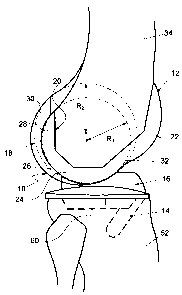
The epicondyle axis of the knee, shown in Figure 8 as epicondyle line 46,
extends between
the centre of radius of curvature C1 of the lateral condyle articular surface
and the centre of
radius of curvature C2 of the medial condyle articular surface. The posterior
condyle axis,
shown in Figure 8 as posterior condyle line 48, extends between a point on the
lateral
posterior condyle articular surface 28 and a corresponding point on the medial
posterior
condyle articular surface 30. The angle "A" formed between the epicondyle line
46 and
the posterior condyle line 48 approximates the norinal alignment of the knee.
Angle "A"
may three degrees, for example.
The anterior articular surface 22 includes a groove 50 for articulation with
the replaced
petella (not shown) of the prosthetic knee 10. The groove 50 is partially
defined by two
obtuse side walls. The side wall are preferably arranged at an angle of "T"
degrees with
respect to each other, as shown in Figure 6. The angle "T" is preferably less
than one
hundred and fifty degrees. The groove 50 is positioned to run along the
anatomical axis 94
CA 02596776 2007-08-02
WO 2006/074503 PCT/AU2005/001974
-10-
of the feinur 34 when the knee 10 is in extension.
The femoral component 12 is shaped to preserve the anterior 51 and posterior
53 ligaments
of the knee of the patient, as illustrated in Figure 6. The ligaments 51,53
extend through a
gap defined by opposed side walls 55,57 of the lateral condyle articular
surface and the
medial condyle articular surface.
The femoral component 12 is made of any suitable biomaterial having the
mechanical
properties necessary to function as a human knee. The femoral component 12 is
preferably
made of titanium, titanium alloy, cobalt chrome alloy, stainless steel or
ceramic, for
example.
The alternative femoral component 12 shown in Figure 5a includes a different
radius of
curvature in the saggital plane on the medial posterior condyle articular
surface 30. The
difference in radius of curvature, amongst other things, assists in locating
the components
of the prosthetic knee 10 the correct positions when fitting the prosthetic
knee to the leg of
the patient.
The tibial component 14 shown in Figures 9 to 12 includes an external
articular surface 56
and a bone contacting surface 58. The tibial component 14 is made of any
suitable
biomaterial having the mechanical properties necessary to function as a human
knee
proximal tibial prosthesis. The tibial component 14 is preferably made of
titanium,
titanium alloy, cobalt chrome alloy, stainless steel or ceramic, for example.
The inferior non-articular portion 58 of the tibial component 14 is shaped to
receive a
resected proximal end 60 of the tibia 52, as shown in Figures 2 and 3. The
bone contacting
non-articular internal surface 58 includes a plurality of chamfer surfaces. In
use, surgeons
malce cuts in the distal end 60 of the tibia 52 that correspond to the chamfer
surfaces of the
tibial component 14, as shown in Figures 13 and 14. Techniques for making
these cuts are
generally known in the art and are not discussed here in detail. The non-
articular portion
62 of the tibial component 14 that engages the proximal end 60 of the tibia 52
includes a
CA 02596776 2007-08-02
WO 2006/074503 PCT/AU2005/001974
-11-
porous metal surface 62, or any other like surface, to promote growth of bone
thereon. The
surface 62 alternatively includes a suitable surface suitable for the use of
orthopaedic bone
cement for fixation of the tibial component 14 to the proximal end 60 of the
tibia 52.
The tibial component 14 is includes a "U" shaped aperture that is at least
partially defined
by two spaced apart opposed medial surfaces 64 that extend from a curved
anterior section
66 of the tibial component 14 towards the posterior of the tibial component
14. The
aperture creates an opening between the superior external articular surface 56
and the
inferior non-articular surface 58 of the tibial component 14. The aperture is
shaped to
receive a wedge of bone 59 preserved on the proximal end 60 of the tibia 52
that includes
the anterior and posterior cruciate ligaments 51,53 of the leg of the patient.
When so
positioned, the cruciate ligaments extend from the tibia 52, through the
aperture towards
the insert 16, as shown in Figure 15. The tibial component 14 thereby
preserves the
cruciate ligaments 51,53.
The outer peripheral edge surface 68 of the tibial component 14 are non-
articular, non-
bone contacting surfaces which are preferably continuous and connect to the
two spaced
apart opposed medial non-articular surfaces 64 posteromedially.
The tibial component also includes a tapered stem 70 coupled to the non-
articular surface
58. The stem 70 is arranged in a position between the curved anterior non-
articular section
66 and an anterior section of the non-articular surface 58. The stem 70
extends in a
posteroinferior direction facilitating the intersection of a stemmed tibial
component 14 in a
cruciate preserving total knee replacement.
The articular surface 56 of the tibial component 14 is adapted to
cooperatively engage and
move with respect to the matched insert 16. The articular surface 56 retains
the convex
shape of the apical portion of a sphere, the radius of which approximates that
of the
distance from the knee to the ankle of the patient. The radius of curvature
is, for example,
greater than Rl and R2.
CA 02596776 2007-08-02
WO 2006/074503 PCT/AU2005/001974
-12-
In the alternative tibial component 14 shown in Figure 10b, the lateral
articular surface 55
is less than the medial articular surface 57. In this embodiment, the
articular surface 56 of
the tibial component 14 is shaped to cover the entire contact area of the
bone.
The prosthetic insert 16 shown in Figures 16 to 19 includes:
1. A medial superior articular surface 72;
2. A lateral superior articular surface 74; and
3. An inferior articular surface 76.
The medial superior articular surface 72 is adapted to cooperatively engage
the medial
articular surfaces 26,30 of the femoral component 12. The lateral superior
articular surface
74 is adapted to cooperatively engage the lateral articular surfaces 24, 28 of
the femoral
component 12. The inferior articular surface 76 is generally concave and is
shaped to
receive the convex articular surface 56 of the tibial component 14.
The articular surface 74 has a raised section in the anteromedial portion of
the surface 78.
The raised section increases the contact area with the femoral component 12
whilst
avoiding soft tissue impingement.
The insert includes a non-articular surface 80 arranged between the medial
superior
articular surface 72 and the lateral superior articular surface 74. The
arrangement of these
surfaces 72,74,80 defines a central opening 82 in the insert 16 that
accommodates the
cruciate ligaments 51,53 of the patient.
The insert also includes:
1. Two central superior non-articular surfaces 84;
2. Two central inferior non-articular surfaces 86; and
3. Two lateral inferior non-articular surfaces 88.
CA 02596776 2007-08-02
WO 2006/074503 PCT/AU2005/001974
- 13-
The two central inferior non-articular surfaces 86 are preferably generally
flat and are
adapted to preserve the cruciate ligaments. One of the two central superior
non-articular
surfaces 84 is arranged side by side with one of the two central inferior non-
articular
surfaces 86. The other ones of the respective surfaces 84,86 are also arranged
with respect
to each other in the same manner. The surfaces 84,86 of each pair of surfaces
are disposed
at an obtuse angle with respect to each other to avoid soft tissue
impingement.
The two central inferior non-articular surfaces 86 extend inferiorly from
their respective
central superior non-articular surfaces 84 to abut the articular surface 76.
The two lateral inferior non-articular surfaces 88 extend inferiorly to abut
the articular
surface 76. The lateral inferior non-articular surfaces 88 extend superiorly
to abut the non-
articular surface 90.
The insert 16 is made of any suitable biomaterial having the mechanical
properties
necessary to function as a human knee prosthetic insert. The insert 16 is
preferably made
of titanium, titanium alloy, cobalt chrome alloy, stainless steel, ceramic or
polyethylene,
for example.
The right leg 90 of the patient shown in Figure 19 is arranged in an extended
condition of
use. The right leg 46 includes:
1. A femur 34;
2. Prosthetic femoral component 12;
3. Prosthetic insert component 16;
4. Prosthetic tibial component 14; and
5. Tibia 52.
The drawing of the leg 46 indicates:
1. The mechanical axis of the leg, shown as line 92;
CA 02596776 2007-08-02
WO 2006/074503 PCT/AU2005/001974
-14-
2. The anatomical axis of the femur, shown as line 94; and
3. A vertical axis, shown as line 96.
In a normal leg 90, the mechanical axis of the leg 92 is typically arranged an
angle of three
degrees to the vertical axis 96. Further, the anatomical axis of the femur 94
is typically
arranged at an angle of nine degrees to the vertical axis 96. When the
prosthetic knee 10 is
fitted to a patient, the angle between the epicondyle axis 46 and the
posterior condyle axis
48 is three degrees and the posterior condyle axis 48 (also referred to as
distal the femoral
joint line of the prosthetic knee) aligns the anatomical axis of the femur 94
at substantially
nine degrees to the vertical axis 96. In this arrangement, the mechanical axis
of the leg 92
is disposed at an angle of three degrees to the vertical axis 96.
The insert 16 and tibial component 14 are positioned at three degrees of varus
in relation to
the mechanical axis 92. Those skilled in the relevant art will appreciate that
a number of
angles may be employed by the present invention.
The concave lateral and the medial superior articular surfaces 74,72 of the
insert 16 are
shaped to receive respective ones of the lateral and medial condyle articular
surfaces.
Movement of the articulating surface 18 of the femoral component 12 is
controlled by the
shape and configuration of the concave lateral and the medial superior
articular surfaces
74,72 of the insert 16. The shape of the articulating surface 18 of the
femoral component
12 and the corresponding lateral and medial superior articulating surfaces
72,74 of the
insert 16 permit sliding articulation to simulate femoral roll back of the
prosthetic knee 10.
That is, the components 12,14,16 permit posterior/anterior translation of the
femoral
articular surface 18 with respect to the tibial articular surface 56 during
flexion/extension.
The concave shape of the lateral and the medial superior articular surfaces
74,72 of the
insert 16 assists in maintaining a layer of lubrication between the articular
surfaces of the
femoral component 12 and the insert 16.
The concave inferior articular surface 76 of the insert is shaped to receive
the convex
articular surface 56 of the tibial component 14. The arrangement of these two
articulating
CA 02596776 2007-08-02
WO 2006/074503 PCT/AU2005/001974
- 15-
surfaces 76,56 facilitates a wide range of movement between the respective
components
16,14. For example, the convex shape of the articular surface 56 of the tibial
component
14 facilitates sliding articulation with the inferior concave articulating
surface 76 of the
insert. The tibial component 14 can there by rotate with respect to the inset
during
flexionlextension of the prosthetic knee 10. The concave and convex articular
surfaces 76,
56 also assist in maintaining a layer of lubricant between the abutting
portions of the
components.
The prosthetic knee 10 shown in Figure 23 functions in an analogous manner to
that of the
prosthetic knee 10 shown in Figures 1 to 3. However, a posterior section of
the insert 16
has been reshaped to facilitate easier installation of the prosthetic knee.
While we have shown and described specific embodiments of the present
invention, further
modifications and improvements will occur to those skilled in the art. We
desire it to be
understood, therefore, that this invention is not limited to the particular
forms shown and
we intend in the append claims to cover all modifications that do not depart
from the spirit
and scope of this invention.
CA 02596776 2007-08-02
WO 2006/074503 PCT/AU2005/001974
-16-
List of Parts:
Prosthetic knee 10
Femoral component 12
Tibial component 14
Insert 16
External articular surface 18
Bone contacting non-articular internal surface 20
Anterior articular surface 22
Distal lateral articular surface 24
Distal medial articular surface 26
Lateral posterior condyle articular surface 28
Medial posterior condyle articular surface 30
Distal end 32 of the femur 34
Anterior non-articular surface 36
Distal anterior non-articular surface 38, 40a,40b
Posterior non-articular surface 42a42b,44a,44b
Epicondyle line 46
Posterior condyle line 48
Groove 50
Anterior cruciate ligament 51
Posterior cruciate ligament 53
Tibia 52
Lateral articular surface 55
External articular surface 56
Medial articular surface 57
Bone contacting surface 58
Inferior non-articular portion of the tibial component 58
Wedge of bone 59
Proximal end 60 of the tibia 52
Porous metal surface 62
CA 02596776 2007-08-02
WO 2006/074503 PCT/AU2005/001974
-17-
Medial non-articular surfaces 64
Curved anterior non-articular section 66 of the tibial component 14
Outer peripheral edge surface 68 of the tibial component 14
Medial superior articular surface 72
Lateral superior articular surface 74
Inferior articular surface 76
Anteromedial portion of the surface 78
Non-articular surface 80
Central opening 82
Central superior non-articular surfaces 84
Central inferior non-articular surfaces 86
Lateral inferior non-articular surfaces 88
Right leg of a person 90
Mechanical axis of the leg 92
Anatomical axis of the femur 94
Vertical axis 96