Note : Les descriptions sont présentées dans la langue officielle dans laquelle elles ont été soumises.
CA 02596916 2007-08-03
1
Pressure-reducing and regulating Valve Comprising a Tapping Mechanism for a
Pressure
Gas Cartridge That Can Be Attached Underneath a Receptacle Cover
The present invention pertains to a pressure-reducing and -regulating valve
provided as a disposable
part, which has a tapping tip. The valve cooperates during use with a
pressurized gas cartridge, e.g.,
a carbon dioxide cartridge, in order to maintain the gas pressure in a
receptacle, e.g., in a liquid
receptacle, such as a large or small keg of beer, in such a way that,
regardless of the liquid still
present in the receptacle, a gas pressure is present, which is sufficient, on
the one hand, to tap a
beverage even with relatively small amount of liquid remaining in the
receptacle, and which, on the
other hand, keeps the beverage to be tapped fresh. Moreover, maintaining such
a gas pressure
makes it possible to arrange the tapping fitting at any height. In addition,
this valve may comprise
one or more other units: At least one safety valve unit may be provided in
order to release gas into
the environment in case of an erroneously excess pressure that has increased
to values that are too
high. A non-return valve unit may prevent the pressure prevailing in the can
and, with this, liquid
from reaching the valve area. Of course, the valve according to the present
invention may also be
used for other purposes.
Beer is now offered, among other things, in small metal kegs of, e.g., 5 L
capacity. These kegs have
in a small lower area of the side wall an integrated tap, which is pushed into
the receptacle before
the first use. A vent valve, which usually sits in the fill hole of the can,
is located in the cover.
When the beer in such a keg runs low, it begins to become stale, since the
pressure in the receptacle
drops. To counteract this, a vent valve has already been developed, onto which
a tapping fitting
with a carbonic acid cartridge can be placed as needed. Such a valve is
described, e.g., in DE 199
52473.
The carbonic acid tapping devices known up to now are multi-use devices. The
tapping fitting is
rigidly clamped to the keg by means of a clamp, and the gas cartridge located
outside, which is a
CO2 cartridge, is tapped by means of the cartridge holder. The cartridge is
moved ["beweg" in
German original is a typo for "bewegt" - Tr.Ed.] to the tapping tip of the
valve. After each use, the
device must be cleaned at a cost. Moreover, it is large and cost-intensive, so
that a person, who
would like to tap a keg of beer in the size mentioned only occasionally, will
be thinking precisely
about whether the purchase is worth it. -
The present invention intends to create help here and to provide a valve unit
for a tapping system,
with which, on the one hand, the pressure within the receptacle can be
maintained at a level even at
a low beverage filling level, which ensures the tapping of fresh tasting,
highly carbonated beer or
the like, which, however, on the other hand, takes up little space outside of
the receptacle.
The present invention accomplishes this object by providing a valve unit
according to claim 1, and
in particular in the embodiments of claims 2 through 5 and 6 through 8.
Additional elements of the
valve unit can be provided according to claims 9 through 17.
CA 02596916 2007-08-03
2
The valve unit according to the present invention is suitable, in combination
with a pressure source,
e.g., a carbon dioxide cartridge, as a disposable part for especially smaller
receptacles containing
carbonated beverages or the like and here quite particularly for beer.
According to the present
invention, a valve with the following functions is provided: It shall be able
to tap the pressure
source for maintaining the pressure in the receptacle, to reduce the pressure
thereof optionally in a
suitable manner, and to regulate the pressure within the receptacle. In a
preferred embodiment of
the present invention, the valve unit shall additionally be able to perform a
safety valve function, if
the pressure in the valve unit, partly also in the receptacle, should become
too high.
The valve according to the present invention can be attached to a can in
combination with a usual
tap, for example, a disposable tap, as it has become known from DE 198 35 569
or DE 198 25 929
A1, but in particular with an arrangement according to EP 04 01 4958.5. In
this case, it can be
inserted into a central bunghole or fill hole; however, it is preferably
inserted eccentrically into the
front side cover of the can so that the tap, which may be located relatively
far above in the side wall
of the receptacle according to EP 04 01 4958.5, is not hindered by the
cartridge protective sleeve,
which is connected to the valve unit and which projects inwards, or vice
versa. However, the latter
is not mandatory. The tap may, as needed, be equipped with a compensator
system, with which the
tapping pressure can be reduced and finely adjusted in relation to the inside
pressure.
According to the present invention, it is possible in a first embodiment of
the present invention that
the gas cartridge located therein is already tapped during the mounting of the
valve unit in the cover
and its assembly with the cartridge protective housing. In this case, gas
escaping from the cartridge
advances up into a pressure chamber, wherein the pressure building up in this
case is used for this
purpose to seal this chamber via a valve (in the form of a reducing valve)
until the valve unit is
actuated. The actuation takes place, as needed, from outside in such a way
that the said sealing
valve is opened against the force that the gas pressure exerts, such that gas
from the pressure
chamber can enter a pressure-regulating chamber. A spring system ensures that
the pressure ratios
in the two chambers are subsequently balanced out in relation to one another
in such a way that a
pressure of ca. 1.0 bar to 1.5 bar is set in the interior of the valve unit.
If this pressure is reached,
the reducing valve closes again. If a higher pressure prevails in the interior
of the valve unit than in
the internal chamber of the liquid receptacle, gas can escape from the valve
unit into the receptacle
interior. If, however, the pressure in the interior of the liquid receptacle
is higher than in the valve
unit, a non-return valve prevents liquid from the main chamber of the
receptacle from entering the
pressure-regulating chamber of the valve unit.
As an alternative, in a second embodiment of the present invention, the
tapping of the cartridge can
be brought about from outside only at the point in time, from which a
compensation of the drop in
pressure in the liquid receptacle is needed. An activation of the valve unit
then preferably at the
same time brings about the tapping of the cartridge and the setting of the
sealing valve to the above-
mentioned pressure balance. It is possible to provide a non-return valve in
this embodiment as well.
Instead of this or in addition, however, provisions may be made for the
cartridge to be tapped via a
sleeve-like internal housing, whose rotary movement leads to an axial movement
of a tapping tip
connected to it in the direction of the opening of the gas cartridge. In this
case, the presence of a
rotatable internal housing in the outer housing of the valve unit may for this
purpose be used, when
the gas cartridge is tapped or was tapped, for gas to be able to escape from
the pressure-regulating
chamber, for example, because holes in the side wall of the internal housing
and in the outer
CA 02596916 2007-08-03
3
housing of the valve unit come to lie above one another only after this rotary
movement, so that gas
can escape into the interior of the receptacle.
The valve unit according to the present invention may be attached sealingly in
a corresponding hole
of the liquid receptacle in any manner. This hole is preferably found
eccentrically in the cover area
of the liquid receptacle. For example, the upper end area of the valve holder
of the valve unit may
be connected to a vent valve plug, which, besides the attaching and sealing
function, has, moreover,
actuating means for transmitting a force into the interior of the valve unit,
which opens the sealing
valve of the pressure chamber, as mentioned above, against the gas pressure,
when this vent valve
plug is used in combination with the above-mentioned first embodiment of the
present invention.
Instead of this, it may also be provided with means, which make possible the
tapping of the gas
cartridge according to the said second embodiment of the present invention
only after the complete
mounting and sealing of the liquid receptacle. The vent valve plug may have
dimensions and
sealing surfaces/locking claws in such a way that it is used as a sealing plug
for the valve unit
according to the present invention, with which this is anchored in the hole of
the liquid receptacle.
Instead of using a vent valve plug, the valve unit may also be inserted
directly into the hole of the
liquid receptacle by means of sealing means.
At any rate, it is advantageous if the valve unit according to the present
invention has at least one
safety system, by means of which a too-high pressure in the pressure-
regulating chamber can be
reduced and can be discharged outside into the surroundings of the liquid
receptacle. In the case of
the second embodiment of the present invention, this system may also dissipate
excess pressure in
the liquid receptacle. If a non-return valve is present, this is not
necessary, however. Moreover, an
additional, second safety system may be desirable, which, in case of sealing
problems in the
immediate vicinity of the tapping tip, leads an undesirable excess pressure
out of the chambers
present there and to the outside.
The present invention shall be explained in detail based on the figures, in
which:
Figure 1 shows a liquid receptacle with a first embodiment of the valve unit
according to the present
invention, which valve unit is connected to a CO2 pressure cartridge located
in a cartridge protective
housing 3 and is mounted eccentrically in the cover of the receptacle, so that
enough space remains
for the arrangement of a tap with feed tube,
Figure 2 shows a second embodiment of the valve unit according to the present
invention in a view
similar to Figure 1,
Figures 3 and 4 show general views of the various parts of the embodiments of
the valve unit shown
in Figures 2 and 1, which may comprise the same according to the present
invention, wherein each
shows a state after the mounting and the sealing of the receptacle filled with
liquid, but before the
actuation of the valve unit,
Figure 5 shows the valve unit according to Figure 1 in the activated state,
Figure 6 shows details of the embodiment of the valve unit according to the
present invention
shown in Figure 2,
CA 02596916 2007-08-03
4
and Figures 7 and 8 illustrate the axial movement of the internal housing and
of the tapping tip of
the embodiment shown in Figure 2, wherein Figure 7 shows the valve unit in a
position, in which
the tapping tip has still not broken through the seal of the gas cartridge,
but has already moved a
little bit downwards in the axial direction, and Figure 8 shows the valve unit
in the stopped position,
in which the tapping tip has already broken through the seal of the gas
cartridge.
Identical reference numbers are used for identical elements of all figures and
embodiments.
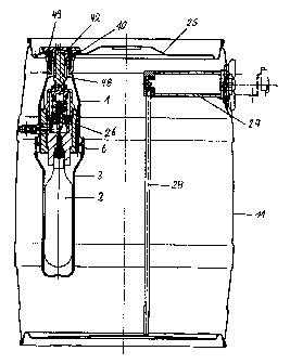
Figure 1 shows a valve unit 26 according to the present invention comprising a
cartridge and valve
holder 1, whose upper extension with locking claws meshes with a recess
(outside cage) of a vent
valve plug. The vent valve plug is designed in some parts analogously to the
plug that has become
known from DE Patent No. 199 52 473 C2. Thus, it has lateral sealing surfaces
49, with which it is
anchored in the eccentric hole 10 in the cover 25 of the beverage receptacle
11, as well as a rotary
cover 42 with tapping cover plate. The rotary cover has a centrally arranged
rotary cover mount,
into which a tapping screw 48 is pushed. The vent valve projects only slightly
over the cover level
and is not higher than the cover edge, such that it does not prevent a
stacking of receptacles on top
of one another.
On the inside of the receptacle, a cartridge protective housing 3 is attached
at the valve holder 1,
into which a cartridge 2 can be inserted. Furthermore, Figure 1 shows the
arrangement of a tap 27
with a feed tube 28. Because a sufficient pressure can always be maintained in
the receptacle 11 by
means of the valve unit, it is not necessary for the tap to be located near
the bottom; instead, it may
be mounted far above in order to make the tapping easier, as described in EP
04 01 4958.5. Here,
the liquid is fed via a feed tube 28.
Figure 2 shows an alternative valve unit 26, which is likewise inserted into a
round, eccentric hole
in the cover 25 of the receptacle 11. Here as well, the valve unit projects
only slightly over the
cover level, because it sits rigidly with its outer housing, the valve holder
1, and sealingly in the
hole 10 via a sealing means 7. The stopping can take place in the known
manner. This may be,
e.g., by means of a threaded ring, which meshes with an external thread of the
cartridge and valve
holder 1, in such a way that the wall of the receptacle cover between this
ring and a projection of the
cartridge and valve holder 1 can be clamped. Instead of this, the valve holder
1 may have two
peripheral flanges or locking wedge rings, between which a sealing ring is
located. When the valve
holder is locked in the hole of the receptacle that is provided for this
purpose, the edges of this hole
come to lie on the seal and are held by the flanges or the locking wedge
rings.
Figure 3 shows the valve unit 26 according to the present invention according
to Figure 2 in
combination with a cartridge protective housing 3 with cartridge 2 located
therein in the assembled
state after mounting in the liquid receptacle cover. The cartridge and valve
holder 1 has a tapping
lever 5 with an original safety mechanism, a safety valve 34, a pressure-
reducing valve located in an
internal housing 4 and a tapping tip 8. The tapping tip is still located above
the gas cartridge
tapping point; only when an escape of gas in the liquid receptacle is desired
in order to compensate
the drop in pressure caused by the tapping of a beverage, it [tapping tip] is
lowered by actuating the
tapping lever up into the tapping point, as described in detail in the
explanations of Figures 6 and 7.
Figure 4 shows the valve unit shown in Figure 1 with more precision in all its
main components.
One recognizes the valve holder 1, which is enclosed by the vent valve plug 36
and is connected to
CA 02596916 2007-08-03
a cartridge holder 3, into which the cartridge 2 is inserted, by external
force or via locking claws 44.
When mounting, the gas cartridge 2 is pushed into the metal core 41 by means
of a thread 30 and is
tapped by the tapping tip 8 of the valve unit. The gas escaping from the gas
cartridge reaches a
pressure chamber 33 by means of a channel in the tapping tip, but is prevented
from flowing further
due to the cooperation of the valve lifter head 14 with the sealing surfaces
or seats 17. A seal 17.1
seals the tapping hole and tapping tip against the metal core 41 and the
thread 30.
By actuating the tapping cover plate 50, gas from the pressure chamber 33
reaches the pressure-
regulating chamber 13, as is shown in detail in Figure 5. The tapping cover
plate 50 is lifted for this
purpose and rotated; the tapping screw 48, which is located in frictional
contact connection in an
internal recess of the rotary cover 42, is correspondingly also rotated. A
screw thread 37, which is
located in the lower area of the tapping screw on the outside thereof, meshes
with a corresponding
threaded part in the inside neck area of the regulator seal 35. Therefore, the
rotary movement of the
tapping cover plate at the same time brings about an axial movement of the
tapping screw 48 in the
direction of the gas cartridge. For this purpose, the thread may have, for
example, such a pitch that
the rotary cover 42 needs ca. 3 rotations until the tapping screw rests
against the regulator seal 35.
A compression spring (coil spring) 16, which tensions a fitting element 51
against the tapping screw
48, is arranged in the interior of the regulator seal. If the tapping screw
rests against the regulator
seal, it exerts a high force onto a spring disk held by a diaphragm holder 32
via the fitting element
and the compression spring 16. The diaphragm holder 32 presses inwardly
against a regulator plate
21, which limits the pressure-regulating chamber 13 in the upward direction.
The regulator plate
transmits the pressure to a valve element from the valve lifter 18 and valve
lifter head 14, which
then moves in the axial direction away from the seal 17 downwards.
Consequently, gas may reach
the pressure-regulating chamber 13 via a continuous channel 39 from the
pressure chamber 33.
The pressure-regulating chamber 13 is, as has been mentioned, limited in the
upward direction by
the regulator plate 21 and otherwise by the metal core 41 and the valve seal
14, 17. The internal
housing 4, which is per se held by the valve holder 1, extends around the
metal core. The pressure-
regulating chamber 13 is connected to the interior of the liquid receptacle 11
via lateral, continuous,
aligned holes both in the metal core 41 and in the internal housing 4 and in
the valve holder 1. In
order to prevent gas or liquid from the main chamber of the liquid receptacle
from entering the
pressure-regulating chamber 13 in case of unfavorable pressure ratios, the
lateral hole in the valve
holder 1 is embodied as a non-return valve 38.
The valve unit according to the present invention is, as mentioned above, set
at a pressure of ca. 1.0
bar to 1.5 bar (prestressing of the compression spring 16). If this pressure
is reached, the valve lifter
head 14 is sealed by means of the compression spring 9 against the pressure of
the compression
spring 16. If the internal pressure of the receptacle is over 1.0 bar to 1.5
bar, the non-return valve
38 remains closed. If the internal pressure of the receptacle drops below this
value, the valve opens,
and gas, e.g., C02, flows until a pressure balance is reached.
Figures 6 through 8 show the details of a specific valve unit according to
Figure 2 with safety valve;
the cartridge protective housing 3 connected to the cartridge and valve holder
1 can only be partly
seen. The connection between the two parts is identified with reference number
6; this [connection]
may be embodied in any way, e.g., as a screw thread.
CA 02596916 2007-08-03
6
In its upper area on the outside, the valve unit has means 7, with which the
cartridge and valve
holder I can be held sealingly and tightly in the hole of the liquid
receptacle. Otherwise, the
cartridge and valve holder is preferably embodied essentially as a continuous
tube with circular
cross section, which has a lateral hole 20, which can communicate with a hole
19 of the internal
housing 4. The internal housing 4 is attached both rotatably and displaceably
in the axial direction
against the cartridge and valve holder 1 via a thread. In its starting
position, in which a cartridge
located in the cartridge protective housing is not yet tapped (see also Figure
7), it is located in such
a position that the hole 19 is not connected to the hole 20 of the cartridge
and valve holder.l. As a
result, no liquid is able to enter the valve before putting into operation.
The internal housing 4 is
attached at the cartridge and valve holder 1 is in such a way that a rotary
movement at the same
time brings about a displacement of the internal housing inwardly in the
direction of the cartridge
tip (see also Figure 8). By means of a handle or a strap 5 on the outside of
the valve unit, it can be
twisted from the outside of the liquid receptacle, wherein the tapping tip 8,
which is arranged in its
end area directed inwardly by means of a tapping disk 29 and a threaded ring
30, is moved inwardly
in the axial direction until it taps the cartridge 2.
A channel, through which gas from the cartridge can escape into a chamber 33,
runs through the
tapping tip. By means of a compression spring 9 in this chamber, a valve
lifter is tensioned against
a valve seat 17; this valve seals the chamber 33 against a continuous hole,
which is connected to a
pressure-regulating chamber 13. This [chamber] is limited laterally by the
internal housing, but has
a connection to the outside via the hole 19, which communicates with the hole
20 in the cartridge
and valve holder after the displacement of the internal housing 4 in the
direction of the cartridge tip,
such that there is a connection of the pressure-regulating chamber 13 to the
main chamber of the
liquid receptacle after tapping the cartridge.
On its side opposite the valve unit 14, 17, i.e., in the outward direction,
the pressure-regulating
chamber is limited by a spring disk 15, which is held sealingly at the
internal housing. In the center,
it is held by a diaphragm holder 32, via which it is prestressed by means of a
compression spring 16
held by a regulator seal 35. The diaphragm holder 32 presses inwardly against
a regulator plate 21,
which transmits the pressure to a valve lifter 18, which is arranged in a
regulator sleeve 31. The
piston 18 transmits the pressure to the head 14 of the valve lifter. If the
pressure drops in the liquid
receptacle and thus in the pressure-regulating chamber below a value settable
via the compression
spring 16, then the countertensioning, which presses the spring disk in the
direction of the
compression spring 16, drops to a value, beyond which the pressure exerted by
the compression
spring 16 becomes so high that the piston 18 presses the head of the valve
lifter downwards and gas
can escape from the chamber 33 until a pressure has again built up in the
pressure-regulating
chamber 13, which presses the spring disk sufficiently far against the
compression spring 16 that the
piston 18 returns to its starting position.
For safety technical considerations, it is preferred that the internal housing
is no longer moved back
into its starting position after tapping the cartridge. This can be achieved
in that a spring-mounted
bolt is provided in the internal housing, which locks into place in a hole in
the valve holder 1 in the
final position.
All embodiments of the present invention have in common the fact that a safety
system can be
provided, which prevents the pressure in the pressure-regulating chamber 13
from being able to
increase beyond a predetermined value, e.g., because of a malfunction of the
reducing valve. For
CA 02596916 2007-08-03
7
this purpose, a hole 52, which extends within the interior of the compression
spring 16, is located in
the diaphragm holder 32. The diaphragm holder 32 has, in alignment with the
tubular interior 52
provided with holes, a hole, which is connected to the pressure-regulating
chamber 13 via small-
sized cross holes 25, which are arranged between the diaphragm holder and the
regulator plate 21 or
are designed as recesses in the diaphragm holder. Small holes 24 are arranged
in the side wall of
the diaphragm holder 32 near its outer end. An overpressure hose piece 23 is
pushed over this end
up to over the holes and seals these under the working pressures provided. If
the pressure in the
pressure-regulating chamber 13 increases too sharply, the gas pressure also
increases in the interior
of the sleeve; the gas presses against the wall of the plastic tube and causes
a slit to form between
the sleeve and the tube, through which the gas can escape into the spring
chamber of the spring 16
formed in the regulator sea135. From there it reaches the regulator seal 35
from same via holes. In
embodiments, in which the valve unit is attached in the cover of the liquid
receptacle via additional
means, such as the vent valve plug 36, these means must, of course, then be
equipped with holes or
channels, which make possible a release of the excess pressure from the valve
unit according to the
present invention. Such vent holes are designated as 43 in the attached
figures.
In the second embodiment of the present invention, as is shown, e.g., in
Figure 2, an undesirable
excess pressure in the interior of the liquid receptacle may also be released
with this safety system.
In embodiments with a non-return valve between the pressure-regulating chamber
13 and the main
chamber of the liquid receptacle, such an excess pressure may not even form at
all in the receptacle.
In addition, a second safety system may be provided for preventing the
formation of a too-high
pressure with sealing problems at the tapping tip 8, e.g., in the area of the
thread 30. Such a system
is shown in Figure 5. In the embodiment of this figure, gas, which escapes via
the thread 30, would
reach the chamber between the gas cartridge and the cartridge protective
housing 3. A safety
channel 40 in the internal receptacle 4 and optionally holes 43 in the rotary
cover 42 lead a pressure
possibly building up correspondingly in the outward direction. In other
embodiments, for example,
the valve unit according to Figures 2, 3 and 6 through 8, corresponding
channels would have to be
provided, in the case of this embodiment, for example, in the cartridge
protective housing 3, in the
valve holder 1 and optionally in the internal housing 4 of the valve holder.
An increased pressure
cannot form in the liquid receptacle due to the additional safety system.
The valve according to the present invention can be operated, for example, at
the following
pressures: Starting pressure in the gas cartridge: ca. 60 bar. Pressure in the
pressure-regulating
chamber: 1 to 3 bar; triggering of the safety valve at more than 3 bar
overpressure.
CA 02596916 2007-08-03
8
List of Reference Numbers
1 Valve holder
2 Cartridge
3 Cartridge protective housing
4 Internal housing
Tapping lever
6 Screw thread of valve holder/cartridge holder
7 Outer sealing means
8 Tapping tip
9 Compression spring
Hole in the receptacle cover
11 Liquid receptacle
13 Pressure-regulating chamber
14 Valve lifter head
Spring disk
16 Compression spring
17 Sealing surface for valve lifter
17.1 Seal
18 Valve lifter
19 Lateral hole in the internal housing
Lateral hole in the valve holder
21 Regulator plate
23 Overpressure hose
24 Holes
Cross hole
26 Valve unit
27 Tap
28 Feed tube
29 Tapping disk
Threaded ring
31 Regulator sleeve
32 Diaphragm holder
33 Pressure chamber
34 Safety valve
Regulator seal
36 Valve plug
37 Screw thread
38 Non-return valve
39 Continuous channel
Safety channel
41 Metal core
42 Rotary cover
43 Vent hole
44 Locking claw
48 Tapping screw
49 Sealing ring
CA 02596916 2007-08-03
9
50 Tapping cover plate
51 Fitting element
52 Hole
*****