Sélection de la langue

Search

Sommaire du brevet 2597340 

Énoncé de désistement de responsabilité concernant l'information provenant de tiers

Une partie des informations de ce site Web a été fournie par des sources externes. Le gouvernement du Canada n'assume aucune responsabilité concernant la précision, l'actualité ou la fiabilité des informations fournies par les sources externes. Les utilisateurs qui désirent employer cette information devraient consulter directement la source des informations. Le contenu fourni par les sources externes n'est pas assujetti aux exigences sur les langues officielles, la protection des renseignements personnels et l'accessibilité.

Disponibilité de l'Abrégé et des Revendications

L'apparition de différences dans le texte et l'image des Revendications et de l'Abrégé dépend du moment auquel le document est publié. Les textes des Revendications et de l'Abrégé sont affichés :

  • lorsque la demande peut être examinée par le public;
  • lorsque le brevet est émis (délivrance).
(12) Demande de brevet: (11) CA 2597340
(54) Titre français: ACTIONNEUR ELECTRO-MAGNETIQUE
(54) Titre anglais: ELECTROMAGMETIC ACTUATOR
Statut: Réputée abandonnée et au-delà du délai pour le rétablissement - en attente de la réponse à l’avis de communication rejetée
Données bibliographiques
(51) Classification internationale des brevets (CIB):
  • F16K 31/06 (2006.01)
(72) Inventeurs :
  • DYER, DAVE (Royaume-Uni)
  • MAATJE, HENK
  • WEIDE, HENK
(73) Titulaires :
  • BAKER HUGHES INCORPORATED
(71) Demandeurs :
  • BAKER HUGHES INCORPORATED (Etats-Unis d'Amérique)
(74) Agent: MARKS & CLERK
(74) Co-agent:
(45) Délivré:
(86) Date de dépôt PCT: 2006-02-09
(87) Mise à la disponibilité du public: 2006-08-17
Requête d'examen: 2007-08-08
Licence disponible: S.O.
Cédé au domaine public: S.O.
(25) Langue des documents déposés: Anglais

Traité de coopération en matière de brevets (PCT): Oui
(86) Numéro de la demande PCT: PCT/US2006/004572
(87) Numéro de publication internationale PCT: US2006004572
(85) Entrée nationale: 2007-08-08

(30) Données de priorité de la demande:
Numéro de la demande Pays / territoire Date
60/651,530 (Etats-Unis d'Amérique) 2005-02-09
UNKNOWN (Etats-Unis d'Amérique) 2005-02-09

Abrégés

Abrégé français

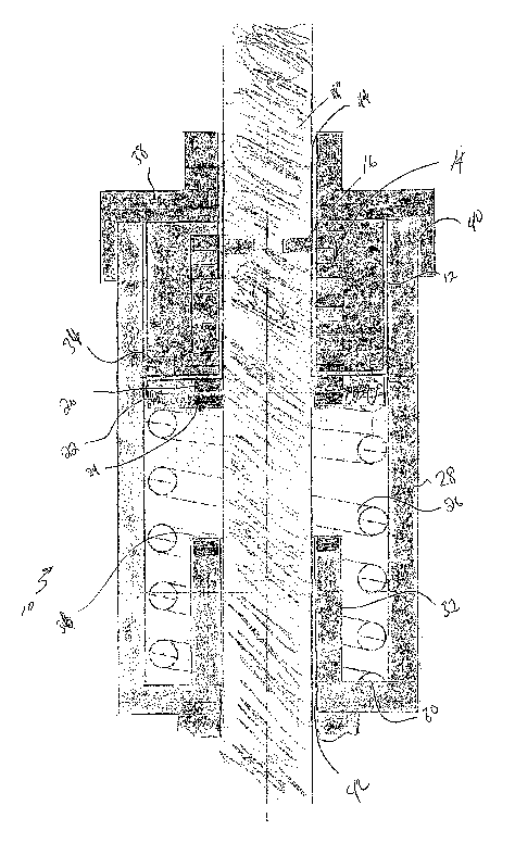
L'invention concerne un actionneur de valve électro-magnétique. Cet actionneur comprend un logement (28), une tige d'entraînement (18) s'étendant à partir du logement, et un électro-aimant (14) en communication fonctionnelle avec le logement et la tige d'entraînement, cette dernière étant sensible à un champ magnétique généré par l'électro-aimant. L'invention concerne également un actionneur de valve électro-magnétique/mécanique. Cet actionneur comprend un logement, une tige d'entraînement possédant une tête de tige s'étendant à partir du logement, une vis-mère supportée par le logement, un moteur en communication par entraînement avec la vis-mère et un poussoir en communication par filetage avec la vis-mère, le poussoir pouvant être fixé sélectivement par voie électro-magnétique à la tête de tige. L'invention se rapporte en outre à un procédé de mise en oeuvre d'un actionneur de valve. Ce procédé consiste à appliquer un courant sur un électro-aimant afin de pousser une tige d'entraînement dans le sens opposé à la force de sollicitation d'un ressort de fermeture en vue de l'ouverture d'une valve, et à maintenir le courant dans l'électro-aimant en vue du maintien de la valve en position ouverte.


Abrégé anglais


Disclosed herein is an electro-magnetic valve actuator. The actuator includes
a housing (28) , a drive stem (18) extending from the housing, and an electro-
magnet (14) in operable communication with the housing and drive stem, the
drive stem being responsive to a magnetic field generated by the electro-
magnet. Further disclosed is an electro-magnetic-mechanical valve actuator.
The actuator includes a housing, a drive stem having a stem head extending
from the housing, a lead screw supported by the housing a motor in driving
communication with the lead screw and a follower in threaded communication
with the lead screw, the follower selectively electro-magnetically affixable
to the stem head. Yet further disclosed herein is a method for operating a
valve actuator. The method includes applying a current to an electro-magnet to
urge a drive stem against a closure spring to open a valve and maintaining
current in the electro-magnet to keep the valve in the open position.

Revendications

Note : Les revendications sont présentées dans la langue officielle dans laquelle elles ont été soumises.


Claim 1. An electro-magnetic valve actuator comprising:
a housing;
a drive stem extending from the housing; and
an electro-magnet in operable communication with the housing and drive
stem, the drive stem being responsive to a magnetic field generated by the
electro-
magnet.
Claim 2. An electro-magnetic valve actuator as claimed in claim 1 wherein one
of the drive stem and the housing carries the electro-magnet.
Claim 3. An electro-magnetic valve actuator as claimed in claim 2 wherein the
other of the drive stem and the housing carries a permanent magnet in operable
communication with the magnetic field of the electro-magnet when generated.
Claim 4. An electro-magnetic valve actuator as claimed in claim 2 wherein the
other of the drive stem and the housing also carries an electro-magnet.
Claim 5. An electro-magnetic valve actuator as claimed in claim 1 wherein the
housing further comprises a hold-open magnet.
Claim 6. An electro-magnetic valve actuator as claimed in claim 5 wherein the
hold-open magnet is an electro-magnet.
Claim 7. An electro-magnetic valve actuator as claimed in claim 5 wherein the
actuator includes a biasing member to urge the drive stem to a closed position
and
against which biasing member the hold-open magnet acts.
6

Claim 8. An electro-magnetic-mechanical valve actuator comprising:
a housing;
a drive stem having a stem head extending from the housing;
a lead screw supported by the housing;
a motor in driving communication with the lead screw; and
a follower in threaded communication with the lead screw, the follower
selectively electro-magnetically affixable to the stem head.
Claim 9. An electro-magnetic-mechanical valve actuator as claimed in claim 8
wherein at least one of the stem head and the follower includes an electro-
magnet and
the other of which includes one of a permanent magnet, an electro-magnet and a
magnetic material.
Claim 10. An electro-magnetic-mechanical valve actuator as claimed in claim 8
wherein the housing further includes a member selectively electro-magnetically
affixable to the follower.
Claim 11. An electro-magnetic-mechanical valve actuator as claimed in claim 10
wherein the member acts against a biasing member that biases the drive stem
toward
the closed position.
Claim 12. A method for operating a valve actuator comprising:
applying a current to an electro-magnet to urge a drive stem against a closure
spring to open the valve; and
maintaining current in the electro-magnet to keep the valve in the open
position.
Claim 13. A method for operating a valve actuator as claimed in claim 12
wherein the method further includes removing current from the electro-magnet
to
allow the valve to close.
7

Claim 14. A method for operating a valve actuator as claimed in claim 13
wherein removing current includes both intentional and unintentional removal.
Claim 15. A method for operating a valve actuator as claimed in claim 12
wherein the method includes engaging a mechanical assembly to open the drive
stem.
Claim 16. A method for operating a valve actuator as claimed in claim 12
wherein the method further includes applying a current to a hold-open electro-
magnet.
8

Description

Note : Les descriptions sont présentées dans la langue officielle dans laquelle elles ont été soumises.


CA 02597340 2007-08-08
WO 2006/086549 PCT/US2006/004572
ELECTROMAGNETIC ACTUATOR
CROSS REFERENCE TO RELATED APPLICATIONS
[0001] This application claims the benefit of an earlier filing date from U.S.
Provisional Application Serial No.: 60/651,530 filed February 9, 2006, the
entire
disclosure of which is incorporated herein by reference.
BACKGROUND
[0002] In the hydrocarbon exploration and recovery industry, valves are
required in great numbers and configurations. Commonly, the most critical
valves are
hydraulically controlled. This is because hydraulically controlled valves have
been
shown to be effective and reliable through the test of time. In order to
ensure proper
operation of such valves, many regulating bodies have elected to require that,
inter
alia, a volume of hydraulic fluid equal to three times that actually required
to operate
the valve(s) be kept on hand. Such a volume of fluid requires a large amount
of
storage space. Storage space on an oilrig is at a premium, thus making the use
of the
hydraulically controlled valves (when regulated) less desirable.
[0003] In addition to the foregoing, environmental regulatory authorities have
recently begun implementing regulations directly restricting the use of
hydraulic fluid.
This of course makes the use of hydraulically actuated valves even more
problematic.
[0004] Because of the foregoing, alternative means to actuate valves are
welcomed by the art.
SUMMARY
[0005] Disclosed herein is an electro-magnetic valve actuator. The actuator
includes a housing, a drive stem extending from the housing, and an electro-
magnet in
operable communication with the housing and drive stem, the drive stem being
responsive to a magnetic field generated by the electro-magnet.
[0006] Further disclosed herein is an electro-magnetic-mechanical valve
actuator. The actuator includes a housing, a drive stem having a stem head
extending
from the housinig, a lead screw supported by the housing a motor in driving
1

CA 02597340 2007-08-08
WO 2006/086549 PCT/US2006/004572
communication with the lead screw and a follower in threaded communication
with
the lead screw, the follower selectively electro-magnetically affixable to the
stem
head.
[0007] Yet fiu-ther disclosed herein is a method for operating a valve
actuator.
The method includes applying a current to an electro-magnet to urge a drive
stem
against a closure spring to open a valve and maintaining current in an electro-
magnet
to keep the valve in the open position.
BRIEF DESCRIPTION OF THE DRAWINGS
[0008] Referring now to the drawings wherein like elements are numbered
alike in the several Figures:
[0009] Figure 1 is a schematic cross-sectional view of an electro-magnetic
actuator in a closed position;
[0010] Figure 2 is a schematic cross-sectional view of the electro-magnetic
actuator of Figure 1 in an open position;
[0011] Figure 3 is a schematic cross-sectional view of an electro-magnetic
mechanical actuator in a closed position; and
[0012] Figure 4 is a schematic cross-sectional view of the actuator of Figure
3
in an open position.
DETAILED DESCRIPTION
[0013] Referring to Figure 1 an embodiment of an electro-magnetic actuator
for an oil field valve is illustrated in cross-section. The actuator 10 is
magnetically
controllable based upon application of a current to a coil 12. Current applied
to coil
12 results in a magnetic field generated about electro-magnets 14. The field
created
thereby works to move a stator 16 at drive stem 18 in a directional manner
toward an
opposite end of the magnets 14 than depicted in Figure 1 (see Figure 2
position). The
field created about magnets 14 also urges one or more magnets 20 away from
magnets
14. Magnet(s) 20 may be permanent magnets or may be electro-magnets.
[0014] As is illustrated in the drawing Figure 1, magnets 20 are mounted at a
spring flange 22. The flange 22 is also home to additional one or more magnets
24,
which likewise maybe permanent magnets or electro-magnets. Flange 22 is a part
of
2

CA 02597340 2007-08-08
WO 2006/086549 PCT/US2006/004572
drive stem 18 by integral formation or subsequent affixation. Flange 22 is in
operable
communication with a biasing member 26 such as a spring as shown. Spring 26
urges
the flange such that the valve attains a closed position. Support for spring
26 is found
in a housing 28, which bounds spring 26 between a lower housing 30 and the
flange
22.
[0015] In the illustrated embodiment, housing 28 includes, relative to
movement of flange 22 (and thereby drive stem 18), two discussed features. The
first
feature is a pedestal 32 that extends from the lower housing 30 toward flange
22 and
the second is a flange stop 34 to stop flange movement at an appropriate
stroke.
Pedestal 32 supports a hold open magnet 36 which may be a permanent magnet or
an
electro-magnet providing that between the magnet(s) 24 and magnet(s) 36 at
least one
(set) is an electro-magnet to provide for selective magnetic field reversal
and for fail
safe functionality. These concepts will be discussed further hereunder.
[0016] Finally, housing 28 is mateable with actuator head 38. Although not
specifically shown, it is intended that the actuator 10 be environmentally
sealed at
interface 40 between head 38 and housing 28 and additionally at bore 42 to
drive stem
18 and bore 44 to drive stem 18. Environmental sealing may be accomplished in
a
number of ways including the use of 0-rings as is well known to one of
ordinary skill
in the art.
[0017] The actuator 10 as described relies upon magnetic field generation to
move from a closed position (Figure 1) to an open position (Figure 2).
Primarily the
coil 12 creates the initial magnetic field in magnets 14. That field urges
stator 16
toward the open position (linear motor concept). This can be the sole opening
force
or may be supplemented by magnet(s) 20, 24 and 36 polarized to produce
attractive
fields. Where magnets 20, 24 and 36 are electro-magnets, the attractive forces
generatable and repulsive forces generatable provide selective polarity of
either one of
each cooperable magnet set (i.e., 20 and 14 or 24 and 36) and may be changed
as ~
desired to enhance operation of the system. It is also to be appreciated that
the device
is inherently fail-safe since if power is lost for any reason, the electro-
magnets
immediately lose the magnetic field and the spring 26 (compressed by action of
the
magnetic fields) is free to act to move the actuator to the closed position
shown in
Figure 1.
3

CA 02597340 2007-08-08
WO 2006/086549 PCT/US2006/004572
[0018] In another embodiment, referring to Figures 3 and 4 an electro-
magnetic/mechanical actuator 100 is illustrated. The fail-safe benefit of the
foregoing
embodiment is maintained in this embodiment in that the open condition (Figure
4)
requires power supplied to an electro-magnet. Where power is lost to the
actuator, it
automatically moves to the closed position. Although the actuator disclosed
hereunder is similar to the foregoing actuator, the components are each
different
enough to require distinct numerals. Therefore, 100 series numerals of the
numerals
used above are not intended to bear relation thereto.
[0019] Still referring to both of Figures 3 and 4, a housing 110 includes a
first
end cap 112 and a second end cap 114. The end caps are to be fixedly attached
to
housing 110 in a reliable manner, and in particular embodiments, in an
environmentally sealed manner. End cap 114 includes a through bore 116
configured
and dimensioned to receive a drive stem 118. End cap 114 also provides a
spring seat
120 for a spring 121 which may be a coil spring as illustrated or may be
another
biasing member or arrangement.
[0020] End cap 112 includes an opening 122 for through passage of a drive
shaft 124 from motor 126. End cap 112 also provides support for stanchions 128
which themselves support a stop 130 for buffer 132. In the illustrated
embodiment
buffer 132 is a coil spring but could be other arrangements capable of
dampening the
movement of the drive stem 118 in a closing action. Stop 130 provides a spring
seat
134 for spring 132. Stanchion 128 and stop 130 are fixedly in position and not
intended to move.
[0021] Housing 110 includes supports 140 and 142 that function to rotatably
support a lead screw. In the illustrated embodiment, two lead screws 144 are
employed about 180 degrees apart from one another. Each lead screw 144 is
driven
by a drive member 150 that may be a belt or chain, or may be substituted by a
gear
drive arrangement, etc. The drive members 150 are in operable communication
with
motor shaft 124 (via V-groove in this depiction) so that rotary movement from
the
motor is transmitted to the drive members 150 and thereby the lead screws 144.
-
[0022] Mounted to each lead screw 144 is a follower 152. The follower may
be a single component in annular form to engage both lead screws as
illustrated or
may be individual components, one on each lead screw. The purpose of
follower(s)
4

CA 02597340 2007-08-08
WO 2006/086549 PCT/US2006/004572
152 is to support magnet(s) 154 to hold a stem head 156 when power is
supplied. By
magnetically (e.g., electro-magnetically) attaching stem head 156 to
follower(s) 152,
the lead screws 144 are in a position to actuate the drive stem 118 to an open
position
as shown in Figure 4. In this position the actuator has caused the valve to
open. To
assist in maintaining that position and to avoid back driving of lead screws
144, a
second electro-magnetic hold down 148 is provided in an extension 146 of
supports
142. This electro-magnet hold down 148 is also on the same power feed as the
other
electro-magnets and so will fail-safe as well. Upon loss of electrical power
either
intentionally or unintentionally, the magnetic field generated by magnets 154
will be
lost thereby leaving nothing to inhibit the biasing action of spring 121 from
moving
the drive stem 118. Following release of the magnetic field and spring 121
action, the
actuator will be in the position shown in Figure 3. In order to reopen the
actuator, the
motor is run in reverse, thereby moving follower(s) 152 toward motor 126;
reinitiating power and thereby generating a magnetic field at magnets 154.
This in
turn attracts stem head 156 sufficiently to allow follower(s) 152 to urge the
drive stem
118 into the open position against the spring force of spring 121. The
actuator is
inherently fail-safe as is the foregoing embodiment, does not require
hydraulic fluid
and eliminates the need for space occupying supporting infrastructure on the
rig.
[0023] While preferred embodiments have been shown and described,
modifications and substitutions may be made thereto without departing from the
spirit
and scope of the invention. Accordingly, it is to be understood that the
present
invention has been described by way of illustrations and not limitation.
What is claimed is:

Dessin représentatif
Une figure unique qui représente un dessin illustrant l'invention.
États administratifs

2024-08-01 : Dans le cadre de la transition vers les Brevets de nouvelle génération (BNG), la base de données sur les brevets canadiens (BDBC) contient désormais un Historique d'événement plus détaillé, qui reproduit le Journal des événements de notre nouvelle solution interne.

Veuillez noter que les événements débutant par « Inactive : » se réfèrent à des événements qui ne sont plus utilisés dans notre nouvelle solution interne.

Pour une meilleure compréhension de l'état de la demande ou brevet qui figure sur cette page, la rubrique Mise en garde , et les descriptions de Brevet , Historique d'événement , Taxes périodiques et Historique des paiements devraient être consultées.

Historique d'événement

Description Date
Demande non rétablie avant l'échéance 2010-12-08
Inactive : Morte - Aucune rép. dem. par.30(2) Règles 2010-12-08
Réputée abandonnée - omission de répondre à un avis sur les taxes pour le maintien en état 2010-02-09
Inactive : Abandon. - Aucune rép dem par.30(2) Règles 2009-12-08
Inactive : Dem. de l'examinateur par.30(2) Règles 2009-06-08
Inactive : Supprimer l'abandon 2009-03-16
Modification reçue - modification volontaire 2008-10-09
Inactive : Correspondance - Transfert 2008-10-03
Inactive : Abandon. - Aucune rép. à lettre officielle 2008-10-03
Inactive : Lettre officielle 2008-07-03
Inactive : Déclaration des droits - Formalités 2008-04-23
Inactive : Transfert individuel 2008-04-23
Inactive : Page couverture publiée 2007-10-26
Lettre envoyée 2007-10-19
Inactive : Acc. récept. de l'entrée phase nat. - RE 2007-10-19
Inactive : CIB en 1re position 2007-09-14
Demande reçue - PCT 2007-09-13
Exigences pour l'entrée dans la phase nationale - jugée conforme 2007-08-08
Exigences pour une requête d'examen - jugée conforme 2007-08-08
Toutes les exigences pour l'examen - jugée conforme 2007-08-08
Demande publiée (accessible au public) 2006-08-17

Historique d'abandonnement

Date d'abandonnement Raison Date de rétablissement
2010-02-09

Taxes périodiques

Le dernier paiement a été reçu le 2009-01-23

Avis : Si le paiement en totalité n'a pas été reçu au plus tard à la date indiquée, une taxe supplémentaire peut être imposée, soit une des taxes suivantes :

  • taxe de rétablissement ;
  • taxe pour paiement en souffrance ; ou
  • taxe additionnelle pour le renversement d'une péremption réputée.

Les taxes sur les brevets sont ajustées au 1er janvier de chaque année. Les montants ci-dessus sont les montants actuels s'ils sont reçus au plus tard le 31 décembre de l'année en cours.
Veuillez vous référer à la page web des taxes sur les brevets de l'OPIC pour voir tous les montants actuels des taxes.

Historique des taxes

Type de taxes Anniversaire Échéance Date payée
Taxe nationale de base - générale 2007-08-08
TM (demande, 2e anniv.) - générale 02 2008-02-11 2007-08-08
Requête d'examen - générale 2007-08-08
TM (demande, 3e anniv.) - générale 03 2009-02-09 2009-01-23
Titulaires au dossier

Les titulaires actuels et antérieures au dossier sont affichés en ordre alphabétique.

Titulaires actuels au dossier
BAKER HUGHES INCORPORATED
Titulaires antérieures au dossier
DAVE DYER
HENK MAATJE
HENK WEIDE
Les propriétaires antérieurs qui ne figurent pas dans la liste des « Propriétaires au dossier » apparaîtront dans d'autres documents au dossier.
Documents

Pour visionner les fichiers sélectionnés, entrer le code reCAPTCHA :


Pour visualiser une image, cliquer sur un lien dans la colonne description du document (Temporairement non-disponible). Pour télécharger l'image (les images), cliquer l'une ou plusieurs cases à cocher dans la première colonne et ensuite cliquer sur le bouton "Télécharger sélection en format PDF (archive Zip)" ou le bouton "Télécharger sélection (en un fichier PDF fusionné)".

Liste des documents de brevet publiés et non publiés sur la BDBC .

Si vous avez des difficultés à accéder au contenu, veuillez communiquer avec le Centre de services à la clientèle au 1-866-997-1936, ou envoyer un courriel au Centre de service à la clientèle de l'OPIC.

({010=Tous les documents, 020=Au moment du dépôt, 030=Au moment de la mise à la disponibilité du public, 040=À la délivrance, 050=Examen, 060=Correspondance reçue, 070=Divers, 080=Correspondance envoyée, 090=Paiement})


Description du
Document 
Date
(aaaa-mm-jj) 
Nombre de pages   Taille de l'image (Ko) 
Dessins 2007-08-07 4 1 391
Dessin représentatif 2007-08-07 1 162
Description 2007-08-07 5 260
Abrégé 2007-08-07 2 132
Revendications 2007-08-07 3 80
Dessins 2008-10-08 4 144
Accusé de réception de la requête d'examen 2007-10-18 1 177
Avis d'entree dans la phase nationale 2007-10-18 1 204
Courtoisie - Lettre d'abandon (R30(2)) 2010-03-01 1 165
Courtoisie - Lettre d'abandon (taxe de maintien en état) 2010-04-05 1 172
PCT 2007-08-07 3 81
Correspondance 2007-10-18 1 26
Correspondance 2008-07-02 1 24
Correspondance 2008-04-22 2 57