Note : Les descriptions sont présentées dans la langue officielle dans laquelle elles ont été soumises.
CA 02597887 2007-08-14
WO 2006/088372 PCT/N02006/000060
SYSTEM AND METHOD FOR WELL INTERVENTION
The present invention relates to a system and a method for well intervention
in
subsea installed water- or hydrocarbon producing wells, comprising a surface
vessel or rig, with equipment to handle and control a connection string for
downhole tools, and also a system for supply of and return of drilling fluid,
from
which the connection string for the downhole tool runs down into a drilling
hole
on the subsea through open sea without a riser or landing string being fitted,
where a X-mas tree with an associated blow out preventer is arranged on the
well, and where a return line for drilling fluid runs up to said system on the
surface vessel or the rig.
The invention is related to a system and a method that makes it possible to
intervene in subsea installed water- or hydrocarbon producing wells without
having to use a riser connection to the surface vessel or device. The system
and method cover work in subsea installed water- or hydrocarbon producing
wells carried out with the help of a drill pipe, coiled tubing or wireline
operations
(both braided and slickline), and also said methods based on use of new
composite and thermoplastic materials and complimentary solutions. The
system and method also make it possible for longer tool strings to be used
with
a much reduced height of the intervention system, and then especially the
length of the sluicing-in pipe.
Today's methods to carry out well interventions in subsea installed wells with
the help of a drill pipe or coiled tubing are based on the use of a riser
connection between the well head and the surface equipment on the surface
vessel or the device. This requires a large, and thus costly, surface vessel
or
device, which must have room for blow-out preventer valves (BOP) for a riser,
and also other equipment that is required for pressure control fluid treatment
and stand-by handling. The fact that pressurised well fluid is led directly to
the
vessel or the device via the riser leads to regulatory demands, which in turn
can
lead to a more expensive vessel or device. Today however, there are systems
that make riserless drilling of top section in oil wells and gas wells
possible.
These systems are based on controlling the well pressure and removing
cuttings/drilling fluid by using a pump solution connected to the device.
Return
of drilling fluid and any cuttings occur via a flexible return solution.
CA 02597887 2007-08-14
WO 2006/088372 PCT/N02006/000060
2
There are systems and methods today that make riserless wireline operations
possible on subsea based wells with the help of an underwater sluice pipe
system. The existing systems are based on placing a blowout preventer on top
of the existing X-mas tree of the well. On top of the blow-out preventer, one
or
more sluice pipe lengths are placed which are used to sluice the tool string
when it shall enter or come out of the well. A sealing mechanism that seals
round the wireline when it is driven into the well is placed on the top.
One of the challenges of the existing underwater sluice pipe systems is the
limitation of the system with respect to the length of the tool string which
can be
driven. The limitation is based on available sluice pipe length which in turn
is
limited by several factors, not to transfer too much power to the permanent
underwater subsea installation. The limitation in length of the tool string
leads
to several wireline operations having to be carried out in the well to achieve
the
operation's goal, which in turn leads to a longer and thus more expensive
system.
In the main, there are two different systems available today. One system
flushes the hydrocarbons from the intervention system, i.e. the temporary
equipment used for the intervention, back into the well on the subsea and the
second flushes the hydrocarbons back to the surface vessel or the device. The
advantage of flushing the hydrocarbons from the intervention equipment back
into the well on the subsea, is that one does not have to lead hydrocarbons to
a
surface vessel or device, something which can reduce the requirements of the
vessel or device, lower the risk and thus achieve a cheaper operation.
Systems and methods for well intervention in subsea installed wells from a
vessel or the like on the ocean surface, without the use of a riser, are known
from US 6,415,877 and US 6,386,290, comprising equipment for handling and
controlling a connection string for downhole tools and also a system for
supply
of and return of drilling fluid, where a X-mas tree and a blow-out preventer
are
arranged on the well, and a return line for drilling fluid that runs up to the
ocean
surface vessel.
WO Al 02/20938 describes a system for well intervention, where a coiled
tubing unit with driving-in equipment is placed on a blow out preventer on an
underwater wellhead.
CA 02597887 2010-05-14
WO 2006/088372 PCT/N02006/000060
3
None of these solutions mentioned describe use of a removable intervention
valve In the drill pipe which is arranged to function as a testable, temporary
barrier for sluicing-in purposes.
The present invention aims to make possible the carrying out of a more
flexible
and less expensive well intervention by combining existing and new technology
with new methods and systems.
The system with associated methods has, in the main, four principal
configurations, i.e. system and method for drilling operations in subsea based
wells with a drill pipe or coiled tubing, from a vessel or device, without the
use
of a riser, and also a system and method for intervention in a well with a
coiled
tubing or wireline in subsea based water- or hydrocarbon producing wells, from
a vessel or device, without the use of a riser.
A preferred embodiment of the system according to the invention is
characterised by the characteristic part of the independent claim 1, in that a
removable intervention valve is arranged in the drilling hole/production pipe,
where the intervention valve is set up to function as a testable, temporary
barrier.
The intervention valve is preferably a collectable and regulated / controlled
valve
for sluicing-in purposes, and the valve can be closed to close off the well
and be
opened to drive through downhole tools in the well.
In connection with drilling operations with a drill pipe or coiled tubing, a
drilling
fluid return system is preferably arranged on the top of the blowout
preventer,
through which the connection string for the downhole tools are led, and said
return line runs from there and up to the system for supply and return of
drilling
fluid.
In connection with coiled tubing operations or wireline operations in water-
or
hydrocarbon producing wells, a sluicing device, such as one or more sluice
pipes with a seal between coiled tubing or wireline, is preferably arranged on
the top of the blowout preventer, through which the connection string for the
downhole tool is led, and said return line runs from there and up to the
system
for supply and possibly return of fluid.
CA 02597887 2010-05-14
WO 2006/088372 PCT/N02006/000060
4
Adjoining the sluice device, a coiled tubing injector or a cable injector can
be
arranged, and the surface vessel or the rig, can comprise a coiled tubing unit
or
a wireline unit and/or a coiled tubing injector or a cable injector.
A preferred embodiment of the method is characterised
in that before the connecting string is led into the well, the drilling
hole/production pipe is closed, whereupon a removable intervention valve is
installed in the drilling hole/production pipe, where the intervention valve
is set
up to function as a testable, temporary barrier which makes it possible for
the
drilling hole to be used as a sluice for the downhole tool that shall go into
the
well, and to open the intervention valve to let through the connection string
with
the downhole tool that shall be used in the well.
The intervention valve is preferably installed at a depth in the drilling hole
/
production pipe which satisfies the requirements for length of well tools and
any
length for stand-by operational tools (fishing). Before the intervention valve
is
opened to let through the downhole tool, the valve is tested and verified as a
temporary well barrier, and that any well fluid, such as hydrocarbons and/or
gas, is
flushed out of the intervention equipment. Control of well pressure and well
fluid
can be carried out by using a drilling fluid return system in combination with
complimentary valves.
in connection with drilling operations in subsea based wells with a drill pipe
or a
coiled tubing, the well is preferably killed first with a suitable killing
fluid that is
pumped into the well, when the wellhead pressure has been established at the
same level as the surrounding pressure, and the well is verified to be without
pressure and stable in relation to the surrounding pressure (dead), the drill
pipe
or coiled tubing with the necessary downhole equipment is lowered down into
the well, where the drilling fluid return system takes care of the pressure
control
during the drilling operation and also transports drilling fluid to the
surface
vessel or rig.
In connection with completion, the drilling fluid return system can be driven
to
the well for change of drilling fluid to diesel or a similar fluid that does
not keep
control of the well pressure, and a safety valve which closes the system can
be
fitted between vessel and return system for drilling fluid..
CA 02597887 2007-08-14
WO 2006/088372 PCT/N02006/000060
In connection with drilling operations with coiled tubings in subsea based
wells,
an underwater coil pipe injector or well tractor can be used to provide the
necessary force to the drilling tool, a coiled tubing injector on the surface
can
5 be used to pull up the coiled tubing up from the underwater injector head,
possibly to pull the coiled tubing with well tractor and well tool out of the
well.
In connection with coiled tubing operations in water- and hydrocarbon
producing subsea based wells, the coiled tubing is preferably pulled out of
the
well after the downhole operation has been completed, until it is above the
temporary, regulated/controlled injection valve, thereafter the valve can be
closed, necessary tests be carried out and the hydrocarbons be flushed out of
the area and the equipment above the intervention valve, before the
intervention tool and coiled tubing are brought up. The sequence is repeated
as
many times as necessary to achieve the objective of the intervention.
In connection with wireline operations in water- and hydrocarbon producing
subsea based wells, the tool string is preferably lowered, during the
invention,
as well as any well tractor, with the help of a wireline winch on the surface
and
when the deviation in the well is so large that the tool does not go further
down
due to gravity, the well tractor can be brought in, whereupon the well tractor
pushes the tool and pulls the wireline until the required depth has been
reached.
After the downhole operation has been completed, the wireline is pulled out of
the well until it is above the temporary, controlled intervention valve,
thereafter
the valve can be closed, the necessary tests be carried out and the
hydrocarbons be flushed out of the area and the equipment above the
intervention valve, whereupon the intervention tools and wireline are brought
up. The sequence is repeated as many times as necessary to achieve the
purpose of the intervention.
In connection with intervention in water- or hydrocarbon producing subsea
based wells with wireline or coiled tubing, well fluids and gas between the
intervention valve and X-mas tree of the well are preferably flushed/forced
out
of the area with the help of pumping-in inhibitory fluid with substantially
higher
specific gravity than the well fluids, at the same time as pressure is
released
CA 02597887 2007-08-14
WO 2006/088372 PCT/N02006/000060
6
from the limited area as high up as possible to avoid too high pressure and
also
to flush out well fluids and gases.
Well fluids and gases between the intervention valve and the X-mas tree of the
well can be forced out of the area by letting the inhibitory fluid sink down
toward
the intervention valve and replace the well fluid and gases from the
intervention
valve and up toward the dedicated outlet in the X-mas tree or in dedicated
outlets in other parts of the intervention equipment, i.e. the temporary
equipment used for the intervention, until all well fluid and gases are out of
the
production pipe, whereupon the flushing and circulation system of the
intervention system can carry out the rest of the flushing out.
The invention shall now be described in more detail, with reference to the
enclosed figures, in which:
Figure 1 shows an embodiment of the present invention in connection with
drilling operations in subsea based wells with a drill pipe.
Figure 2 shows an embodiment of the present system in connection with drilling
operations in subsea based wells with a coiled tubing.
Figure 3 shows an embodiment of the present system in connection with coiled
tubing operations or wireline operations in subsea based wells.
Figures 4a-4c shows an example of an intervention valve to be used in the
present invention, in a closed, half open and open position, respectively.
In the following description, components such as drill pipe, coiled tubing,
wireline, etc., have been given the same reference numbers, i.e. all are
referred
to with reference number 20. Common features of said components are that
they function as a connection between downhole tools and equipment on a
surface vessel or rig, and said drill pipe, coiled tubing, wireline etc., can
thereby
also be collectively described as a connection string for the downhole tool.
Correspondingly, equipment for handling of said components has been given
the same reference number, but it must be understood by a person skilled in
the art that this equipment can be different dependent on whether it is a
drill
pipe, coiled tubing, wireline etc., that shall be handled. With the expression
downhole tool, one must understand different tools for the operation in a
well,
i.e. equipment for drilling operations, intervention equipment, equipment for
logging, measuring, fishing, etc.
CA 02597887 2007-08-14
WO 2006/088372 PCT/N02006/000060
7
In the following, different embodiment examples shall be described, but it
must
be understood that other configurations are possible within the framework of
the invention.
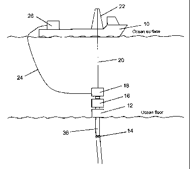
Configuration 1: System for drilling operations in subsea based wells with a
drill
pipe, from a vessel or device without the use of a riser. The system refers to
figure 1. The system is comprised of a surface vessel 10 or a device/rig that
is
placed above the relevant subsea installation and a X-mas tree 12. In a
drilling
hole/production pipe 36, one can install a collectable and
regulated/controlled
intervention valve 14 for sluicing-in purposes. The intervention valve 14 is a
testable, temporary barrier that can be opened to drive through tools for use
in
the well. The intervention valve can remain until the well task has been
completed and can withstand impacts from falling tools, and also can be
opened and be closed many times. On top of the X-mas tree (Xmas tree) of the
well is placed a multifunction well blowout preventer (BOP) 16, which can
include slipping, holding and cutting/sealing functions, and also functions
for
circulation of fluids. A drilling fluid return system 18 is placed on the top
of the
multifunction well blowout preventer 16. The drill pipe 20 runs into the well
through open sea, and is controlled and handled at the surface with the help
of
dedicated systems 22. The supply and return of the drilling fluid can be
handled
with the help of a dedicated system 26 placed on the vessel 10 or the rig. A
flexible return line 24 can connect the underwater drilling fluid system with
a
dedicated surface system.
A method for drilling operations in subsea based wells with a drill pipe, from
a
vessel or device, without the use of a riser. The method refers to figure 1.
Before drilling commences, the well must be killed with a suitable killing
fluid
that is pumped into the well. When the wellhead pressure has been established
at the same pressure as the surrounding pressure, and the well verified to be
without pressure and stable in relation to the surrounding pressure (dead),
one
can lower the drill pipe 20 with the necessary downhole tools into the well
through the temporary equipment for intervention, i.e. the intervention
equipment, (with use of intervention valve 14, this must be opened first). The
drilling fluid return system 18 will take care of the pressure control during
the
drilling operation, and also transport drilling fluid to the surface vessel 10
or
device/rig. In connection with completion, the drilling fluid return system 18
is
driven to the well for exchange of drilling fluid to diesel or a similar fluid
that
does not maintain control of the well pressure. A safety valve that shuts-off
the
CA 02597887 2007-08-14
WO 2006/088372 PCT/N02006/000060
8
system at, for example, 5 bar, can be fitted between vessel and return system
for drilling fluid. The method can also be used for under balance drilling.
The
well will then not be without pressure, but have a small overpressure in the
well
in relation to the surrounding pressure at the drilling fluid return system
18. The
drilling fluid return system 18 will then have a pressure control function
built in
for control of the pressure difference, and also that the intervention valve
14 will
be used.
Configuration 2: System for drilling operations with coiled tubings in subsea
based wells from a vessel or a device without the use of a riser. The system
refers to figure 2. The system is comprised of a surface vessel 10 or
device/rig
which is localised above the relevant subsea installation and X-mas tree 12.
In
the production pipe 36, one can install a collectable and regulated/controlled
intervention valve 14 for sluicing in purposes. The intervention valve 14 is a
testable, temporary barrier that can be opened to drive through tools for use
in
the well. The intervention valve 14 preferably remains until the well task has
been completed, can withstand impacts from falling tools and can also be
opened and closed many times. On top of the X-mas tree (Xmas tree) of the
well is placed a multifunction well blowout preventer (BOP) 16 that can
include
slipping, holding and cutting/sealing functions, and also functions for
circulation
of fluids. The drilling fluid return system 18 is preferably placed on the top
of
the multifunction well blowout preventer 16. The coiled tubing 20 runs into
the
well through open sea and is controlled and handled on the surface with the
help of a dedicated handling system 22, coiled tubing unit 28 and surface
coiled tubing injector 32 or with the help of other dedicated systems and
methods for handling. An underwater coiled tubing injector head 30 is placed
on top of the drilling fluid return system 18. This head can alternatively be
left
out with the use of well tractor technology. The supply and return of drilling
fluid
can be handled with the help of a dedicated system 26 placed on the vessel 10
or the device/rig.
Method for drilling operations with coiled tubings in subsea based wells, from
a
vessel or a device without the use of a riser. The method refers to figure 2.
Before drilling, the well must be killed with a suitable killing fluid that is
pumped
into the well. When the wellhead pressure has been established at the same
pressure as the surrounding pressure, i.e. the well has been verified as being
without pressure and stable in relation to the surrounding pressure (dead),
one
can lower down the coiled tubing 20 with the necessary downhole tools in the
CA 02597887 2007-08-14
WO 2006/088372 PCT/N02006/000060
9
well through the intervention equipment (with the use of intervention valve
14,
this must be opened first). The drilling fluid return system 18 will
preferably take
care of the pressure control during the drilling operation, and also transport
cuttings to the surface vessel 10 or the device/rig. An underwater coiled
tubing
injector 30 or a well tractor is used during drilling to provide the necessary
force
to the drilling tool. The coiled tubing injector on the surface 32 is used to
pull
the coiled pipe up from the underwater injector head 30, possibly to pull the
coiled tubing with well tractor and drilling tool out of the well. The method
can
also be used for under balance drilling. The well must then not be without
pressure, but have a small overpressure in the well in relation to the
surrounding pressure at the drilling fluid return system 18. The drilling
fluid
return system 18 will then have a pressure control function built in, for
control of
the pressure difference, and also that the intervention valve 14 will be used.
Configuration 3: System for coiled tubing operations from a vessel or device
in
water- and hydrocarbon producing subsea based wells. The system refers to
figure 3. The system is comprised of a surface vessel 10 or device/rig which
is
localised above the relevant subsea installation and X-mas tree 12. In the
production pipe 36, one can install a collectable and regulated/controlled
intervention valve 14 for sluicing-in purposes. The intervention valve is a
testable, temporary barrier that can be opened to drive through tools for use
in
the well. The intervention valve 14 preferably remains until the well task has
been completed, can withstand impacts from falling tools, and can also be
opened and closed many times. On top of the X-mas tree (Xmas tree) of the
well is preferably placed a multifunction well blowout preventer (BOP) 16 that
can include slipping, holding and cutting/sealing functions and also functions
for
circulation of fluids. On the top of the multifunction well blowout preventer
16 is
preferably placed one or more sluice pipes 34 with a seal between coiled
tubing
20 and well pressure being mounted in the top. The coiled tubing 20 runs into
the well through open sea and is controlled and handled on the surface with
the
help of dedicated handling systems 22, coiled tubing unit 28 and surface
coiled
tubing injector 32 or with the help of other dedicated systems and methods for
handling. An underwater coiled tubing injector head 30 is placed on top of the
sluice pipe 34 and seal. This head can alternatively be left out when well
tractor
or other new technology is used. Any return of well fluid or stimulation of
the
well can be handled with the help of a dedicated system 26 placed on the
vessel 10 or the device/rig, via a hose or umbilical 24.
CA 02597887 2007-08-14
WO 2006/088372 PCT/N02006/000060
Method for coiled tubing operations from a vessel or device in water- and
hydrocarbon producing subsea based wells. The method refers to figure 3.
Before intervention with coiled tubing 20 can start, a collectable
regulated/controlled intervention valve 14 for sluicing-in purposes must be
5 installed. The valve must be installed at a depth that satisfies the
requirements
for length of well tools plus any length for stand-by operation tools
(fishing). By
installing the intervention valve in the production pipe 36, one does not have
to
build the intervention equipment in the height above the blowout valves 16 and
thereby saves handling time and demands for lubricator length. The valve is
10 tested and verified as a temporary well barrier. Hydrocarbons are flushed
out of
the intervention equipment, i.e. the temporary equipment used for the
intervention, before a coiled tubing with tools is driven through open sea and
is
entered into the intervention equipment. Thereafter, the equipment is
installed
and tested before the well is opened and the coiled tubing is driven into the
well
to carry out the downhole operation.
For example, during the intervention underwater coiled tubing injector 32 or
well
tractor is used to provide the necessary power to the tool. The coiled tubing
injector 32 on the surface can be used to pull the coiled tubing 20 up from
the
underwater injector head 30, possibly to pull the coiled tubing with well
tractor
and tool out of the well. The method can also use other, new methods for
driving the coiled tubing (swift). A hosepipe 24 can be connected to the
intervention equipment for any return of fluid from the well. After the
downhole
operation has been completed, the coiled tubing 20 is pulled out of the well
until it is above the temporary, controlled intervention valve 14. Thereafter,
the
valve 14 is closed, necessary tests are carried out and the hydrocarbons are
flushed out of the area and the equipment above the intervention valve before
one can bring up the intervention tool and coiled tubing. The sequence is
repeated as many times as necessary to achieve the purpose of the
intervention.
Configuration 4: System for wireline work operations from a vessel or device
in
water- and hydrocarbon producing subsea based wells. The system refers to
figure 3. The system is comprised of a surface vessel 10 or device/rig which
is
localised above the relevant subsea installation and X-mas tree 12. In the
production pipe 36, one installs a collectable and regulated/controlled
intervention valve 14 for sluicing-in purposes. The intervention valve 14 is a
testable, temporary barrier that can be opened to drive through tools for use
in
CA 02597887 2007-08-14
WO 2006/088372 PCT/N02006/000060
11
the well. The intervention valve 14 preferably remains until the well task has
been completed, can withstand impacts from falling tools and can also be
opened and closed many times. On top of the X-mas tree (Xmas tree) of the
well, is preferably placed a multifunction well blowout preventer (BOP) 16
that
can include slipping, holding and cutting/sealing functions, and also
functions
for circulation of fluids. On top of the multifunction well blowout preventer
16 is
preferably placed one or more sluice pipes 34 with a seal between wireline 20
and well pressure being mounted at the top. The wireline 20 runs into the well
through open sea and is controlled and handled at the surface with the help of
dedicated handling systems 22, wireline unit/winch 28 and possibly surface
cable injector 32 or other surface handling for new types of cables for use in
wells. An underwater cable injector 30 or other underwater systems for new
cable types can be placed on the top of the sluice pipe 34 and seal. This head
can alternatively be left out when a well tractor or other new technology,
which
can push the wireline 20 and the tool string into the well, is used. Any
return of
well fluid or stimulation of the well can be handled with the help of a
dedicated
system 26 placed on the vessel or the device, via a hose and/or umbilical 24.
Method for wireline work operations from a vessel or device in water- and
hydrocarbon producing subsea based wells. The method also refers to figure 3.
The method covers work with known conventional cable types, both braided
wire with and without an electrical conductor (braided wire), and also smooth
wire of metal (slickline). In addition, work with newly developed cable
technology based on composite materials, thermoplastics and metals are
covered. Before intervention with wireline 20 can start, a collectable,
regulated/controlled intervention valve 14 for sluicing-in purposes must be
installed. The valve 14 is installed at a depth that satisfies the
requirements for
length of well tools, well tractor, plus any length for standby operation
tools
(fishing). By installing the intervention valve in the production pipe 36, one
does
not have to build the intervention equipment in the height above the blowout
valves 16 and thereby saves handling time and demands for lubricator length
above the permanent X-mas tree 12. The valve is tested and verified as a
temporary well barrier. Hydrocarbons are flushed out of the intervention
equipment before wireline 20 with tools and any well tractor is driven through
open sea and is entered into the intervention equipment. Thereafter, the
equipment is installed and tested before the well is opened and the tool can
be
driven into the well to carry out the downhole operation. During intervention,
the
tool string and any well tractor are lowered with the help of a cable winch at
the
CA 02597887 2007-08-14
WO 2006/088372 PCT/N02006/000060
12
surface. When the deviation in the well becomes so large that the tool does
not
go in any further, the well tractor is connected. The well tractor will push
the tool
and pull the cable until the required depth has been reached.
With the use of new cable types, a combination of underwater and surface
cable injectors 30,32, other injection systems for new cable types or well
tractor
can be employed to provide the necessary force to the tool to carry out the
well
task. The cable injector 32 or other surface handling of new cable types, is
used to pull the wireline 20 up from the underwater injector head 30, and
possibly to pull the cable with well tractor and tool out of the well.
After the downhole operation has been completed, the wireline 20 is pulled out
of the well until it is above the temporary, regulated/controlled intervention
valve
14. Thereafter the valve 14 is closed and the necessary tests are carried out
and the hydrocarbons are flushed out of the area and equipment above the
intervention valve, before one can bring up the intervention tool and
wireline.
The sequence is repeated as many times as necessary to achieve the
intervention purpose. A hose 24 can be connected to the intervention
equipment for any return of fluid, stimulation or inhibition of the well.
It shall be noted that in an alternative embodiment, use of the intervention
valve
can also be employed on appliances that have X-mas trees located on board
(dry trees).
The figures 4a to 4c show an example of an intervention valve 14 that can be
used in the present invention, but it must be understood that also other valve
types can be used. The valve can, in the main, be put together from known
components.
As shown, the valve 14 can be mechanically fastened to the wall of the
production pipe 36 with the help of conventional "anchors" 42, and a hydraulic
seal can be achieved with the help of known elastomer technology, for
example, an elastomer seal 44. An anchor and elastomer seal 42, 44 can be
activated with the help of a combined placing-pulling-charging-tool on the
wireline. A flapper valve 46 can be placed in the bottom of the valve 14, for
example, similar to those used in permanent downhole safety valves, which are
activated by driving one or more casings 47 back or forth. At the top, a
safety
CA 02597887 2007-08-14
WO 2006/088372 PCT/N02006/000060
13
net 48, in the form of, for example, an inversed flapper, so called tool trap,
can
be placed, that is also activated by driving a casing back or forth.
The valve can have the following components built in: Battery pack 50,
electronics 52 for communication and control and electro hydraulic pack 54 for
opening and closing the valve. Signal transmission to the electronics in the
valve 14 can be transmitted with the help of one of more wireless systems,
either via the steel in the completion, or the medium/fluid in the well.
An example of the main characteristics, systems and functions of a valve, can
be a valve in relation to the following specifications:
- 10 kpsi 150 C design
- Pressure, temperature and capacity sensors
- Surface monitoring and control systems
- Communicates with the subsea control system with the
- help of wireless transmission
- Chargeable in situ battery pack built in
- Electro-hydraulic system for valve activation
- Safety net
- Redundancy of all critical units and systems
- Multifunctional placing, pulling and charging tool
As mentioned, other valves can, of course, be used that meet the requirements
which the present system poses, and the invention is therefore not limited to
the embodiment example shown. Furthermore, it shall be pointed out that use
of the intervention valve can also be employed on appliances that have X-mas
trees located on board (dry trees).