Sélection de la langue

Search

Sommaire du brevet 2598376 

Énoncé de désistement de responsabilité concernant l'information provenant de tiers

Une partie des informations de ce site Web a été fournie par des sources externes. Le gouvernement du Canada n'assume aucune responsabilité concernant la précision, l'actualité ou la fiabilité des informations fournies par les sources externes. Les utilisateurs qui désirent employer cette information devraient consulter directement la source des informations. Le contenu fourni par les sources externes n'est pas assujetti aux exigences sur les langues officielles, la protection des renseignements personnels et l'accessibilité.

Disponibilité de l'Abrégé et des Revendications

L'apparition de différences dans le texte et l'image des Revendications et de l'Abrégé dépend du moment auquel le document est publié. Les textes des Revendications et de l'Abrégé sont affichés :

  • lorsque la demande peut être examinée par le public;
  • lorsque le brevet est émis (délivrance).
(12) Demande de brevet: (11) CA 2598376
(54) Titre français: ETUI EXTENSIBLE D'INSTRUMENT A CORDES
(54) Titre anglais: EXPANDABLE STRINGED INSTRUMENT CASE
Statut: Réputée abandonnée et au-delà du délai pour le rétablissement - en attente de la réponse à l’avis de communication rejetée
Données bibliographiques
(51) Classification internationale des brevets (CIB):
  • G10D 03/00 (2020.01)
(72) Inventeurs :
  • IZEN, MARK S. (Etats-Unis d'Amérique)
  • LIAUTAUD, CEDRIC (Etats-Unis d'Amérique)
  • SMALL, CRAIG (Etats-Unis d'Amérique)
(73) Titulaires :
  • FIRST ACT, INC.
(71) Demandeurs :
  • FIRST ACT, INC. (Etats-Unis d'Amérique)
(74) Agent: SMART & BIGGAR LP
(74) Co-agent:
(45) Délivré:
(22) Date de dépôt: 2007-08-23
(41) Mise à la disponibilité du public: 2008-02-23
Licence disponible: S.O.
Cédé au domaine public: S.O.
(25) Langue des documents déposés: Anglais

Traité de coopération en matière de brevets (PCT): Non

(30) Données de priorité de la demande:
Numéro de la demande Pays / territoire Date
11/507,989 (Etats-Unis d'Amérique) 2006-08-23

Abrégés

Abrégé anglais


An instrument case including a bottom wall, a top wall, and a primary side
wall forming a first compartment. The primary side wall has a lower wall
portion
joined to the bottom wall and an upper wall portion joined to the top wall.
Together,
the upper and bottom walls have a substantially uniform width w to establish
for the
first compartment a first volume for accommodating an instrument having a
maximum width no greater than the uniform width w. A flexible auxiliary side
wall
is contractible within the primary side wall and joins the bottom wall and the
top
wall. The auxiliary side wall has a substantially uniform width W greater than
the
width w of the primary side wall and is expandable to establish a second
compartment with a second volume for accommodating an instrument having a
maximum width greater than the uniform width w.

Revendications

Note : Les revendications sont présentées dans la langue officielle dans laquelle elles ont été soumises.


WHAT IS CLAIMED IS:
1. A stringed instrument case comprising:
a bottom wall:
a top wall;
a primary side wall with a lower wall portion joined to said bottom wall and
an upper wall portion joined to said top wall to form a first compartment,
said
primary side wall having a substantially uniform width w to establish for said
first
compartment a first volume for accommodating an instrument having a maximum
width no greater than said uniform width w; and
a flexible auxiliary side wall contractible within said primary side wall and
joining said bottom wall and said top wall, said auxiliary side wall having a
substantially uniform width W greater than said width w of said primary side
wall
and expandable to establish a second compartment with a second volume for
accommodating an instrument having a maximum width greater than said uniform
width w.
2. A stringed instrument case according to claim 1 including expansion
means for accommodating separation between said upper and lower wall portions
of
said primary side wall and separation between said bottom wall and said top
wall
and thereby expand said auxiliary side wall to establish said second
compartment.
8

3. A stringed instrument case according to claim 2 wherein each of said
upper and lower wall portions have extensive length sections of said uniform
width
w and substantially shorter end sections with outwardly tapered edges forming
triangular protrusions with apices joined establishing at their juncture a
combined
width of said upper and lower wall portions substantially equal to said width
W of
said auxiliary side wall.
4. A stringed instrument case according to claim 3 wherein said expansion
means comprises a zipper forming outer edges of said upper and lower wall
portions,
and said joined apices form the origin end of said zipper.
5. A stringed instrument case according to claim 4 wherein end portions of
said upper and lower wall portions opposite to said tapered end sections
overlap said
tapered end sections.
6. A stringed instrument case according to claim 5 wherein said case has the
overall shape of a stringed instrument with a narrow neck portion and a wider
body
portion, and further comprises a cinch mechanism secured to said neck portion
and
operable to exert a circumferential force thereto.
7. A stringed instrument case according to claim 6 wherein said case is
elongated with said body and neck portions defining opposite ends of said
case, and
said origin end of said zipper is located at an end of said case defined by
said body
portion.
9

8. A stringed instrument case according to claim 1 wherein said case has the
overall shape of a stringed instrument with a narrow neck portion and a wider
body
portion, and further comprises a cinch mechanism secured to said neck portion
and
operable to exert a circumferential force thereto.
9. A stringed instrument case according to claim 8 including expansion
means for accommodating separation between said upper and lower wall portions
of
said primary side wall and separation between said bottom wall and said top
wall and
thereby expand said auxiliary side wall to establish said second compartment.
10. A stringed instrument case according to claim 9 wherein each of said
upper and lower wall portions have extensive length sections of said uniform
width
w and substantially shorter end sections with outwardly tapered edges forming
triangular protrusions with apices joined establishing at their juncture a
combined
width of said upper and lower wall portions substantially equal to said width
W of
said auxiliary side wall.
11. A stringed instrument case according to claim 10 wherein said expansion
means comprises a zipper forming outer edges of said upper and lower wall
portions,
and said joined apices form the origin end of said zipper.
12. A stringed instrument case according to claim 1 wherein said upper wall
portions have an inner edge joined to an outer edge of said top wall and co-
extensive
therewith, and said lower wall portion has an inner edge joined to an outer
edge of
said bottom wall and co-extensive therewith.

13. A stringed instrument case according to claim 12 including expansion
means for accommodating separation between said upper and lower wall portions
of
said primary side wall and separation between said bottom wall and said top
wall and
thereby expand said auxiliary side wall to establish said second compartment.
14. A stringed instrument case according to claim 13 wherein each of said
upper and lower wall portions have extensive length sections of said uniform
width
w and substantially shorter end sections with outwardly tapered edges forming
triangular protrusions with apices joined establishing at their juncture a
combined
width of said upper and lower wall portions substantially equal to said width
W of
said auxiliary side wall.
15. A stringed instrument case according to claim 14 wherein said expansion
means comprises a zipper forming outer edges of said upper and lower wall
portions,
and said joined apices form the origin end of said zipper.
16. A stringed instrument case according to claim 15 wherein end portions of
said upper and lower wall portions opposite to said tapered end sections
overlap said
tapered end sections.
17. A stringed instrument case according to claim 16 wherein said case has
the overall shape of a stringed instrument with a narrow neck portion and a
wider
body portion, and further comprises a cinch mechanism secured to said neck
portion
and operable to exert a circumferential force thereto.
11

18. A stringed instrument case according to claim 17 wherein said case is
elongated with said body and neck portions defining opposite ends of said
case, and
said origin end of said zipper is located at an end of said case defined by
said body
portion.

Description

Note : Les descriptions sont présentées dans la langue officielle dans laquelle elles ont été soumises.

CA 02598376 2007-08-23
EXPANDABLE STRINGED INSTRUMENT CASE
BACKGROUND OF THE INVENTION
Stringed instruments of various types are widely used by both professional
and amateur musicians. Typically, the instruments must be transported to a
location
at which a performance is to occur, On such occasions, transportation of the
instruments is facilitated and instrumeni darnage prevented by moving and
storing
the instruments prior to use in carrying cases generally having a
configuration
conforming to the particular instrument retained. Since stringed instruments
are
made with a variety of shapes and sizes, a properly fitted carrying case is
not always
available for each instrument. Consequently, a musician must either utilize
ill fitted
1 o cases for some instruments or utilize expensive custom fitted cases. This
problem is
accentuated for many musicians who have and utilize multiple stringed
instruments
with various shapes.
The object of this invention, therefore, is to provide a carrying case that
can
be safely used to store and transport stringed instruments of various size and
shape.
1

CA 02598376 2007-08-23
SUMMARY OF THE 1NVENTION
The invention is an instrument case including a bottom wall, a top wall, and a
primary side wall forming a first compartment. The primary side Nvall has a
lower
wall portion joined to the bottom wall and an upper wall portion joined to the
top
wall. Together, the upper and bottom walls have a substantially uniform width
w to
establish for the first compartment a first volume for accorrimodating an
instrument
having a maximtun width no greater than the uniform width w. A flexible
auxiliary
side wall is contractible within the primary side wall and joins the bottom
wall and
the top wall, The auxiliary side wall has a substantially uniform width W
greater
1 o than the width w of the primary side wall and is expandable to establish a
second
compartment with a second volume for accommodating an instrument having a
maximum width greater than the uniform width w. Because of the two
compartments, the case can compactly retain instruments of various size.
According to one feature of the invention, the case includes an expansion
mechanism for accommodating separation between the upper and lower wall
portions of the primary side wall and separation between the bottom wall and
the top
wall to thereby expand the auxiliary side wall and establish the second
compartment.
According to another feature of the iiivention, each of the upper and lower
wall portions have extensive length sections of uniform width and
substantially
shorter end sections with outwardly tapered edges forming triangular
protrusions
with apices.joined establishing at their juncttire a combined width of the
upper and
2

CA 02598376 2007-08-23
lower wall portions substantially equal to the width W of the auxiliary side
wall.
The shorter end sections with triangular protrusions accommodate the expansion
mechanism.
According to yet another feature of the invention, the expansion mechanism
is a zipper forming outer edges of the upper and lower wall portions, and
the,joined
apices form the origin end of the zipper. The zipper simplifies expansion of
the case.
According to still another feature of the invention, end portions of the upper
and lower wall portions opposite to the tapered end sections overlap the
tapered end
sections. The upper and lower wall sections prevent undesired contact of the
zipper
slide vvith other objects.
According to a further feature of the invention, the case has the overall
shape
of a stringed instrument with a narrow neck portion and a wider body portion,
and
further includes a ci-nch mechanism secured to the neck portion and operable
to exert
a circumferential force thereto. The cinch mechanism allows the case to
compactly
receive instruments with different sized necks.
According to an additional feature of the invention, the case is elongated
with
the body and neck portions defining opposite ends of the case, and the origin
end of
the zipper is located at an end of the case defined by the body portion
thereby
eliminating an undesirable btilky protrusion from the sides of the case.
3

CA 02598376 2007-08-23
DESCRIPTION OF THE DRAWINGS
These and other objects and features of the invention will become more
apparent upon a perusal of the following description taken in eonjunction with
the
accompanying drawings wherein:
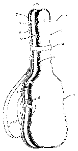
Fig. 1 is a perspective front view of an adjustable carrying case for a string
i nstrument;
Fig, 2 is a left side view of the case shown in Fig. I and with a shoulder
strap
removed;
Fig. 3 is a right side view of the case shown in Fig. ] and with a shoulder
strap removed;
Fig. 4 is an end view of the case shown in Fig. I and with a shoulder strap
removed;
Fig. S is an expanded right side view of the case shown in Fig. I and with a
shoulder strap removed;
. Fig, 6 is a partially contracted right side view of the case shown in Fig. I
and
with a shoulder strap removed;
Fig. 7 is a partial expanded right side view of the case shown in Fig. I and
with a shoulder strap removed; and
Fig. 8 is a partially contracted and partially expanded right side view of the
case shown in Fig. I and with a shoulder strap removed.
4

CA 02598376 2007-08-23-
pESCRIP'I'ION OF THE PREFFRR-ED EMBODIMENT
An elongated carrying case 1 I(Fig. 1) includes a narrow portion 12 for
receiving the neck of a stringed instrument (not shown) and a wider portion 13
for
receiving the instrument's body. Forming the case I I are a top wall 15 and a
bottom
wall 16 joined by a primary side wall I7 having a substantially uniform width
w
(Fig. 6). A handle 18 is joined to the side wall 17, Removably attached to the
bottom wall 16 are a pair of backpack straps 19. A zipper 21 having a pair of
slides
22 allows separation of the top wall l 5 from a portion of the side wall 17
allowing
access to an instrument within the case 11.
The primary side wall 17 (Figs. 2, 3, and 4) includes an upper wall portion 25
and a lower wall portion 26 having outer edges 28, 29 formed by engageable
tabs of
an expansion zipper 27 with an operating pull slide 24, Inner edges of the
wall
portions 25, 26 are joined, respectively, to outer edges 34, 35 of the top and
bottom
walls 15, 16. The upper wall portion 25 has an extensive length section 30 of
- uniform width and a substantially shorter end section 31 with an outwardly
tapered
edge 32 forming a triangular protrusion 33. Similarly, the lower wall portion
26 has
an extensive length section 36 of uniform width and a substantially shorter
end
section 37 with an outwardly tapered edge 38 forming a triangular protrusion
39.
The triangular protrusions 33, 39 are laterally aligned and their apices are
joined
establishing at their juncture 44 a combined width W of the upper and lower
wall
portions 25, 26. End portions 45, 46 of, respectively, the upper wall portion
25 and
5

CA 02598376 2007-08-23
the lower wall portion 26 opposite to the tapered end sections 31 and 37
overlap
those end sections.
Disposed within the primary side wall 17 is a flexible auxiliary side wall 48
(Figs. 4, 5, 7 and 8) also extending between and joining ovter edges of the
top wall
15 and the bottom wall 16, As shown in Fig. 8, the auxiliary side wall 48 has
a
substantially u.niform width W substantially greater than the width w (Figs.
2, 3 and
6) of the primary side wall 17. An upper edge 51 of auxiliary side wall 48
extends
around the entire perimeter 34 of the top wall 15 of the carrying case 1 l and
a lower
edge 53 of the auxiliary side wall 48 extends around the entire perimeter 35
of the
bottom wall 16.
Attached to the narrow portion 12 of the case l 1 is a cinching mechanism 58
including a cinching strap 59 and buckl-e 60. As shown in Fig. 5, the cinching
mechanism 58 can be loosened to allow expansion of the narrow portion 12 of
the
case 11 after opening of the zipper 21. A.lternatively, with the zipper 21
open, the
cinching strap 59 can be tightened to exert a circumferential force on the
narrow
portion 12 and thereby reduce its circumference as illustrated in Fib. 8.
During use of the carrying case 11, the zipper 27 can be closed to contract
the
auxiliary side wall 48 and establish within the case l l a first compartment
61 (Fig. 3)
having a volume which will accommodate a relatively narrow instrument (not
shown) having a width no greater than the given maximum width w. Conversely,
opening of the zipper 27 allows separation of the top and bottom walls 15, 16
and
6

CA 02598376 2007-08-23
expansion of the auxiliary side wall 48 resulting in the creation within the
case 11 of
a second compartment 62 with a larger volume which will accommodate a larger
instrument (not shown) having up to a greater maximum width W as shown in Fig.
5.
The case 11 also will compactly receive an instrument (not shown) having a
body
with a maximum width greater than w but no grcater than W and a neck having a
maximum width in a range between w and W, Such use is facilitated by openino
of
the zipper 27 and tightening of the cinching strap 59 around the narrow
portion 12 of
the case 11.
Obviously, many modifications and variations of the present invention are
1 o possible in light of the above teachings. It is to be understood,
therefore, that the
invention can be practiced otherwise than as specifically described,
7

Dessin représentatif
Une figure unique qui représente un dessin illustrant l'invention.
États administratifs

2024-08-01 : Dans le cadre de la transition vers les Brevets de nouvelle génération (BNG), la base de données sur les brevets canadiens (BDBC) contient désormais un Historique d'événement plus détaillé, qui reproduit le Journal des événements de notre nouvelle solution interne.

Veuillez noter que les événements débutant par « Inactive : » se réfèrent à des événements qui ne sont plus utilisés dans notre nouvelle solution interne.

Pour une meilleure compréhension de l'état de la demande ou brevet qui figure sur cette page, la rubrique Mise en garde , et les descriptions de Brevet , Historique d'événement , Taxes périodiques et Historique des paiements devraient être consultées.

Historique d'événement

Description Date
Inactive : CIB désactivée 2021-11-13
Inactive : CIB en 1re position 2020-08-09
Inactive : CIB attribuée 2020-08-09
Inactive : CIB expirée 2020-01-01
Le délai pour l'annulation est expiré 2012-08-23
Demande non rétablie avant l'échéance 2012-08-23
Réputée abandonnée - omission de répondre à un avis sur les taxes pour le maintien en état 2011-08-23
Demande publiée (accessible au public) 2008-02-23
Inactive : Page couverture publiée 2008-02-22
Inactive : CIB en 1re position 2007-10-12
Inactive : CIB attribuée 2007-10-12
Inactive : Certificat de dépôt - Sans RE (Anglais) 2007-09-25
Demande reçue - nationale ordinaire 2007-09-21

Historique d'abandonnement

Date d'abandonnement Raison Date de rétablissement
2011-08-23

Taxes périodiques

Le dernier paiement a été reçu le 2010-08-04

Avis : Si le paiement en totalité n'a pas été reçu au plus tard à la date indiquée, une taxe supplémentaire peut être imposée, soit une des taxes suivantes :

  • taxe de rétablissement ;
  • taxe pour paiement en souffrance ; ou
  • taxe additionnelle pour le renversement d'une péremption réputée.

Les taxes sur les brevets sont ajustées au 1er janvier de chaque année. Les montants ci-dessus sont les montants actuels s'ils sont reçus au plus tard le 31 décembre de l'année en cours.
Veuillez vous référer à la page web des taxes sur les brevets de l'OPIC pour voir tous les montants actuels des taxes.

Historique des taxes

Type de taxes Anniversaire Échéance Date payée
Taxe pour le dépôt - générale 2007-08-23
TM (demande, 2e anniv.) - générale 02 2009-08-24 2009-08-24
TM (demande, 3e anniv.) - générale 03 2010-08-23 2010-08-04
Titulaires au dossier

Les titulaires actuels et antérieures au dossier sont affichés en ordre alphabétique.

Titulaires actuels au dossier
FIRST ACT, INC.
Titulaires antérieures au dossier
CEDRIC LIAUTAUD
CRAIG SMALL
MARK S. IZEN
Les propriétaires antérieurs qui ne figurent pas dans la liste des « Propriétaires au dossier » apparaîtront dans d'autres documents au dossier.
Documents

Pour visionner les fichiers sélectionnés, entrer le code reCAPTCHA :


Pour visualiser une image, cliquer sur un lien dans la colonne description du document. Pour télécharger l'image (les images), cliquer l'une ou plusieurs cases à cocher dans la première colonne et ensuite cliquer sur le bouton "Télécharger sélection en format PDF (archive Zip)" ou le bouton "Télécharger sélection (en un fichier PDF fusionné)".

Liste des documents de brevet publiés et non publiés sur la BDBC .

Si vous avez des difficultés à accéder au contenu, veuillez communiquer avec le Centre de services à la clientèle au 1-866-997-1936, ou envoyer un courriel au Centre de service à la clientèle de l'OPIC.


Description du
Document 
Date
(aaaa-mm-jj) 
Nombre de pages   Taille de l'image (Ko) 
Abrégé 2007-08-22 1 20
Description 2007-08-22 7 210
Revendications 2007-08-22 5 131
Dessins 2007-08-22 6 113
Dessin représentatif 2008-02-03 1 10
Certificat de dépôt (anglais) 2007-09-24 1 170
Rappel de taxe de maintien due 2009-04-26 1 112
Courtoisie - Lettre d'abandon (taxe de maintien en état) 2011-10-17 1 173
Rappel - requête d'examen 2012-04-23 1 118
Taxes 2009-08-23 1 35