Sélection de la langue

Search

Sommaire du brevet 2598505 

Énoncé de désistement de responsabilité concernant l'information provenant de tiers

Une partie des informations de ce site Web a été fournie par des sources externes. Le gouvernement du Canada n'assume aucune responsabilité concernant la précision, l'actualité ou la fiabilité des informations fournies par les sources externes. Les utilisateurs qui désirent employer cette information devraient consulter directement la source des informations. Le contenu fourni par les sources externes n'est pas assujetti aux exigences sur les langues officielles, la protection des renseignements personnels et l'accessibilité.

Disponibilité de l'Abrégé et des Revendications

L'apparition de différences dans le texte et l'image des Revendications et de l'Abrégé dépend du moment auquel le document est publié. Les textes des Revendications et de l'Abrégé sont affichés :

  • lorsque la demande peut être examinée par le public;
  • lorsque le brevet est émis (délivrance).
(12) Brevet: (11) CA 2598505
(54) Titre français: NACELLE D'EOLIENNE AVEC GRUE DE LEVAGE D'ENTRETIEN INTEGREE POUR ACCEDER A DES ELEMENTS DE TURBINE
(54) Titre anglais: WIND TURBINE NACELLE WITH INTEGRAL SERVICE CRANE FOR ACCESSING TURBINE COMPONENTS
Statut: Périmé et au-delà du délai pour l’annulation
Données bibliographiques
(51) Classification internationale des brevets (CIB):
  • B66C 23/18 (2006.01)
  • B66C 23/02 (2006.01)
(72) Inventeurs :
  • DEHLSEN, JAMES G. P. (Etats-Unis d'Amérique)
  • YARALA, RAHUL R. (Etats-Unis d'Amérique)
(73) Titulaires :
  • CLIPPER WINDPOWER, INC.
(71) Demandeurs :
  • CLIPPER WINDPOWER, INC. (Etats-Unis d'Amérique)
(74) Agent: RICHES, MCKENZIE & HERBERT LLP
(74) Co-agent:
(45) Délivré: 2010-09-07
(86) Date de dépôt PCT: 2007-02-21
(87) Mise à la disponibilité du public: 2007-09-23
Requête d'examen: 2007-08-24
Licence disponible: S.O.
Cédé au domaine public: S.O.
(25) Langue des documents déposés: Anglais

Traité de coopération en matière de brevets (PCT): Oui
(86) Numéro de la demande PCT: PCT/IB2007/000420
(87) Numéro de publication internationale PCT: IB2007000420
(85) Entrée nationale: 2007-08-24

(30) Données de priorité de la demande:
Numéro de la demande Pays / territoire Date
60/785.844 (Etats-Unis d'Amérique) 2006-03-23

Abrégés

Abrégé français

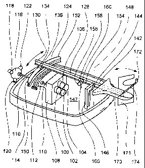
L'invention concerne une grue d'entretien pour éolienne comportant une flèche principale (128) de grue dotée de rails (154) qui reçoivent un chariot (156). Une articulation (144) est installée en un point (148) de pivotement proche de l'extrémité proximale de la flèche principale (128), de sorte qu'une partie arrière de la flèche principale (128) s'étend au-delà du point (148) de pivotement vers l'extérieur de l'éolienne. Une extrémité distale de la flèche principale (128) repose sur une poutre avant. Un actionneur (134) de mouvement latéral déplace la flèche principale (128) dans les deux sens le long de la poutre avant. Le chariot (156) se déplace dans les deux sens le long de la flèche principale (128). Un composant d'éolienne est fixé à un crochet abaissé par câble à partir du chariot (156). Le chariot (156) portant le composant sur le crochet est déplacé vers la partie arrière de la flèche principale (128), qui s'étend au-delà de l'éolienne. Le crochet est abaissé jusqu'au sol afin que le composant puisse être entretenu ou remplacé.


Abrégé anglais


A service crane for a wind turbine comprising a main crane
beam (128) having a track (154) that accommodates a trolley
(156). A hinge (144) is provided at a pivot point (148) near a
proximate end of the main beam (128), such that an aft portion
of the main beam (128) extends beyond the pivot point (148) to
the exterior of the turbine. A distal end of the main beam
(128) rests upon a forward beam. A lateral motion actuator
(134) moves the main beam (128) back and forth along the
forward beam. The trolley (156) runs back and forth along the
main beam (128). A turbine component is attached to a hook
lowered by cable from the trolley (156). The trolley (156)
with the component on the hook is moved to the aft portion of
the main beam (128), which extends beyond the turbine. The
hook is lowered to the ground so that the component can be
serviced or replaced.

Revendications

Note : Les revendications sont présentées dans la langue officielle dans laquelle elles ont été soumises.


Claims:
1. A service crane for a wind turbine, comprising:
a movable main crane beam (128) having a track (154) for
guidance of a trolley (156);
a first frame (146) comprising a hinge (144) at a pivot
point (148), wherein the crane beam (128) is connected to the
hinge (144) such that a portion of the crane beam (128)
extends beyond the pivot point (148);
a stationary beam (124) which is connected with a distal
end of the crane beam (128) such that the crane beam (128) can
laterally move along the stationary beam (124).
2. The service crane of claim 1, wherein the track (154)
is designed as an overhead monorail upon which the trolley
(156) can run.
3. The service crane of claim 1 or 2, wherein the first
frame (146) supports a side structure of the nacelle and is
attatched to a floor of the nacelle.
4. The service crane of any of the claims 1 - 3, wherein
the crane beam (128) rests on the stationary beam (124).
5. The service crane of any of the claims 1 - 4, wherein
the stationary beam (124) is supported by a second frame
(112).
6. The service crane of claim 5, wherein the second frame
(112) comprises the main bearing of the nacelle.
7. The service crane of any of the claims 1 - 6, wherein a
lateral motion actuator (134) is operatively connected to the
crane beam (128) to move the crane beam (128) laterally along
the stationary beam (124).

2
8. The service crane of any of the claims 1 - 7, wherein
the stationary beam (124) is curved.
9. The service crane of any of the claims 1 - 8, wherein a
fairing (170) is mounted to a proximate end (142) of the crane
beam (128), said fairing (170) is shaped so as to reduce drag.
10. The service crane of any of the claims 1 - 9, wherein
a longitudinal motion actuator is operatively connected to the
trolley (156).

Description

Note : Les descriptions sont présentées dans la langue officielle dans laquelle elles ont été soumises.


CA 02598505 2007-08-24
PATENTANWALTE ZENZ = HELBER - HOSBACH & PARTNER = HUYSSENALLEE 58-64 = D-45128
ESSEN
C 411 WO
)B
WIND TURBINE NACELLE WITH INTEGRAL SERVICE CRANE FOR ACCESSING
TURBINE COMPONENTS
Field of the Invention
This invention relates to wind turbines housed in a na-
celle atop a tall tower, and more particularly to an inte-
grated service crane for accessing turbine components atop
high towers.
Description of the Prior Art
The cost of wind-generated electricity has been dropping
due to technological innovations and economies of scale. The
average turbine size is now approximately 1.5 MW with rotor
diameters ranging from 70 to 85m. This class of turbines has
on average a nacelle weight of 50 tons (generators, gear box
and nacelle housing) and a rotor weight of approximately 35
tons. To improve the economics of wind turbines, manufacturers
have been designing taller towers to take advantage of greater
wind energy at higher levels above ground. Manufacturers are
increasingly relying on 80 and 100 m tower designs, rather
than the shorter towers used previously. The cost of lowering
and lifting these weights from/to the top of tall land based
towers for servicing can be prohibitive, mainly due to the
reach of conventional cranes, which require much higher crane
capacity than the actual weight being lifted. This is due to
the bending moment resulting from the reach of conventional
cranes.
US Patent 6,955,025 discloses a method of raising a wind
turbine tower wherein the nacelle and turbine generators
housed in the nacelle are raised together, such that onCe the

CA 02598505 2007-08-24
2
tower is raised the nacelle is at the top of the tower. It is
possible using the method described therein to lower the tower
and nacelle to replace the nacelle and turbine. However for
routine maintenance or replacement of only one component, such
as one generator, it is not cost effective to lower the entire
nacelle. Only the defective component need be lowered.
In the conventional method of the prior art, using a
typical crane at ground level, a drivetrain or a component
thereof is lifted up and over the top of a nacelle located on
the top of a tall tower. The drivetrain or component is then
lowered through a hatch door in the top of the nacelle. The
reverse procedure is used to remove and lower components for
servicing. A 50-ton drivetrain lift would require a 400-600
ton crane. This higher capacity is required due to the high
bending moment associated with the crane reach.
Currently wind turbines require that a crane or special
apparatus to be brought to the wind turbine site for accessing
the components through removal of the nacelle top, in order to
remove components out of the nacelle top and lower them down
to the ground for repair or replacement. This adds a substan-
tial cost for repair and component replacement activity lead-
ing to an increase in the cost of energy.
It is desirable to provide an apparatus which facilitates
the repair and replacement of wind turbine components and low-
ers the costs of such repair and replacement.
SUMMARY OF THE INVENTION
Briefly, the invention is concerned with a wind turbine
service crane for lifting heavy turbine components onto the
top of a very tall tower (80-100m).
The service crane for a wind turbine comprises a movable
main crane beam having a track for guidance of a trolley, a

CA 02598505 2007-08-24
3
first frame comprising a hinge at a pivot point, wherein the
crane beam is connected to the hinge such that a portion of
the crane beam extends beyond the pivot point, a stationary
beam which is connected with a distal end of the crane beam
such that the crane beam can laterlly move along the station-
ary beam.
According to one embodiment of the present invention, the
service crane comprises a main crane beam having a track upon
which a trolley can run. A hinge is provided at a pivot point
near a proximate end of the main beam, such that an aft por-
tion of the beam extends beyond the pivot point to the exte-
rior of the turbine, the hinge being supported by an aft frame
attached to a floor of the nacelle and connected to the main
beam.
A distal end of the main beam rests upon a forward beam,
which is supported by a forward frame attached to the floor of
the nacelle. A lateral motion actuator operatively connected
to the main beam moves the main beam back and forth along the
forward beam. The trolley includes a longitudinal motion ac-
tuator such that the trolley runs back and forth along the
main beam.
In operation the trolley is moved to the interior of the
turbine where a turbine component is attached to a hook that
is lowered by cable from the trolley. The trolley with the
component on the hook is moved to the aft portion of the main
beam, which extends beyond the turbine. The hook is then low-
ered to ground so that the component can be serviced or re-
placed.
The on-board service crane comprises a service crane
structure supporting the housing and provides housing access
to the nacelle exterior, from the service level through a
housing door.

CA 02598505 2007-08-24
4
The service crane enables servicing the upper end of a
wind turbine tower without the need to mobilize a large crane.
The capacity of the service crane is comparable to the
weights lifted.The invention has the advantage that because
the crane is an integral part of the nacelle it avoids the
need to bring a ground level crane or special apparatus to the
wind turbine site for accessing the components through removal
of the nacelle top, in order to remove components and lower
them down the ground for repair or replacement.
The invention has the advantage of lowering the cost of
clean energy by reducing the maintenance and repair costs of
wind turbines.
BRIEF DESCRIPTION OF THE DRAWINGS
The invention will be described in detail with reference to
the drawings in which:
FIGURE 1 is a perspective view of a crane within a na-
celle for lifting turbine components to the nacelle located on
the top of a tower;
FIGURE 2 is a front elevation view of the nacelle shown
in FIGURE 1;
FIGURE 3 is a port side view of the nacelle shown in
FIGURE 1; and,
FIGURE 4 is a perspective drawing showing the nacelle bed
with the crane in the nacelle.
DESCRIPTION OF THE PREFERRED EMBODIMENTS
Refer to FIGURE 1, which is a perspective view of a crane
within a nacelle for lifting turbine components to the nacelle
located on the top of a tower. An on-board 2-ton capacity ser-
vice crane is installed at the rear of the nacelle. A hinged
or roll down door at the rear of the nacelle allows for compo-
nents to be lowered and service tools and other materials to

CA 02598505 2007-08-24
be raised from the ground. This crane allows for service of
brakes, yaw motors, generators, gearbox pinion cartridges and
other components. By avoiding the need to call out even a
small service crane, the use of this on-board service crane is
5 expected to produce a positive benefit to both scheduled and
unscheduled maintenance costs.
Refer to FIGURE 2, which is a front elevation view of the
nacelle shown in FIGURE 1 and to FIGURE 3, which is a port
side view of the nacelle shown in FIGURE 1. The service crane
structure supports the sides and top surfaces of the nacelle.
There is access to the wind turbine components from the ser-
vice level of the nacelle to the exterior through a rear door,
shown in FIGURE 1, and on the right-hand side of the drawing
of FIGURE 3.
The nacelle is partially illustrated in FIGURE 4 and is
of a conventional "bathtub" shaped design. The nacelle houses
a turbine having four generators, 100, 102, 104, 106, con-
nected through a gearbox 108 to a main shaft 110 held in place
by a main bearing 112 attached to the floor of the nacelle
bathtub 114. The main shaft is connected to a rotor hub 116,
which conventionally has three rotor blades, 118, 120, and
122, which are turned by wind. The rotor blades turn the main
shaft 110, which moves gears in the gearbox 108. The gears
turn the generators, which produce electricity from wind
power.
The nacelle service crane includes a curved, stationary
forward I-beam frame 124 attached to the main bearing 112 and
a linear, moveable I-beam crane rail 128 resting at a distal
end 130 on the forward frame 124 by means of four rollers 134,
136, 138, 140. One or more of the rollers are connected to a
lateral motion main beam actuator, such as a servomotor, which
when actuated causes the main beam to move in a lateral direc-
tion. Alternatively, a cable and pulley lateral motion actua-

CA 02598505 2007-08-24
6
tor may achieve lateral motion. The proximate end 142 of the
crane rail 128 is attached via a hinge144 to a stationary aft
frame 146 mounted on the floor of the nacelle bathtub 114. The
crane rail can rotate about the hinge axis 148 within the
outer limits 150, 152 set by the length of the forward frame
upon which the distal end of the crane rail rests. A lower
portion 154 of the crane-rail I-beam acts as an overhead mono-
rail upon which a trolley 156 runs. The trolley is suspended
from the overhead crane rail by means of four wheels
158,160,162, and 164, that straddle the crane rail I-beam. One
or more of the rollers are connected to a longitudinal motion
trolley actuator, such as a servomotor, which when actuated
causes the trolley to move in a longitudinal direction along
the crane rail. Alternatively, a cable and pulleylongitudinal
motion actuator may achieve longitudinal motion.
The trolley has a hook 166 that can be raised and lowered
by a cable 168 and winch (not shown). The hook can be attached
to a component, such as one of the generators, for the purpose
of transporting it to the proximate end of the crane rail,
which is outside of the nacelle. Because the crane rail is
moveable about the pivot point 148, any one of the generators
is accessible to the hook by moving the crane rail laterally.
A fairing 170 is mounted at the proximate end 142 of the crane
rail. The fairing is shaped so as to reduce drag, which may
induce yaw. The winch mechanism is housed within the fairing,
with the additional ability to operate the crane rail actuator
to move the crane rail back and forth on the forward frame 124
and to operate the trolley actuator to move the trolley back-
and-forth along the crane rail 128. The trolley is free to
move past the aft frame 146 to the outside of the nacelle and
into the fairing 170, which is also outside of the nacelle.
Once outside the nacelle the hook 166 with component attached

CA 02598505 2007-08-24
7
can be lowered by the cable to ground level for servicing the
component.
The nacelle is fitted with a hinged or roll-up door 171,
which is operated by a mechanism within the fairing to move
the door out of the way to permit the trolley to exit the rear
of the nacelle. The FAA pod 172 pivots forward on a moveable
arm 174 to permit access. The crane support structural frame,
the curved, stationary forward I-beam frame 124, stationary
aft frame 146 mounted to the nacelle bathtub 114, also serve
as structural support for the sides and top of the nacelle
turbine housing. The sides and top of the nacelle are not
shown in FIGURE 4. The crane structure allows for horizontal
delivery of components to the exterior of the nacelle through
the rear door 171 from which they are lowered to ground level.
Conventional designs require removal of the nacelle top and
component extraction is performed vertically. Lateral movement
of the crane's main beam 128 and the crane trolley 156 move-
ment along the beam permit a full range of turbine component
access. Since the service crane is an integral part of the
wind turbine structure it is always available for maintenance
or component replacement work. The use of existing structure
allows the lifting crane to be cost effective, reliable and
rated to required workload. This helps reduce the cost of
clean energy by reducing the maintenance and repair costs of
wind turbines
While the invention has been particularly shown and de-
scribed with reference to preferred embodiments thereof, it
will be understood by those skilled in the art that the fore-
going and other changes in form and detail may be made therein
without departing from the scope of the invention.

Dessin représentatif
Une figure unique qui représente un dessin illustrant l'invention.
États administratifs

2024-08-01 : Dans le cadre de la transition vers les Brevets de nouvelle génération (BNG), la base de données sur les brevets canadiens (BDBC) contient désormais un Historique d'événement plus détaillé, qui reproduit le Journal des événements de notre nouvelle solution interne.

Veuillez noter que les événements débutant par « Inactive : » se réfèrent à des événements qui ne sont plus utilisés dans notre nouvelle solution interne.

Pour une meilleure compréhension de l'état de la demande ou brevet qui figure sur cette page, la rubrique Mise en garde , et les descriptions de Brevet , Historique d'événement , Taxes périodiques et Historique des paiements devraient être consultées.

Historique d'événement

Description Date
Inactive : CIB expirée 2016-01-01
Le délai pour l'annulation est expiré 2014-02-21
Lettre envoyée 2013-02-21
Accordé par délivrance 2010-09-07
Inactive : Page couverture publiée 2010-09-06
Inactive : Taxe finale reçue 2010-06-25
Préoctroi 2010-06-25
Lettre envoyée 2010-05-21
Un avis d'acceptation est envoyé 2010-03-11
Lettre envoyée 2010-03-11
Un avis d'acceptation est envoyé 2010-03-11
Inactive : Approuvée aux fins d'acceptation (AFA) 2010-03-08
Modification reçue - modification volontaire 2010-02-09
Inactive : Dem. de l'examinateur par.30(2) Règles 2009-12-07
Modification reçue - modification volontaire 2009-09-28
Inactive : Dem. de l'examinateur par.30(2) Règles 2009-04-02
Lettre envoyée 2009-03-31
Lettre envoyée 2009-03-30
Inactive : Correspondance - Transfert 2008-10-23
Lettre envoyée 2008-02-04
Inactive : Transfert individuel 2007-11-28
Inactive : Page couverture publiée 2007-11-27
Inactive : CIB en 1re position 2007-11-26
Inactive : CIB attribuée 2007-11-26
Inactive : CIB attribuée 2007-11-22
Demande reçue - PCT 2007-09-24
Lettre envoyée 2007-09-24
Inactive : Acc. récept. de l'entrée phase nat. - RE 2007-09-24
Demande publiée (accessible au public) 2007-09-23
Exigences pour une requête d'examen - jugée conforme 2007-08-24
Toutes les exigences pour l'examen - jugée conforme 2007-08-24

Historique d'abandonnement

Il n'y a pas d'historique d'abandonnement

Taxes périodiques

Le dernier paiement a été reçu le 2010-01-05

Avis : Si le paiement en totalité n'a pas été reçu au plus tard à la date indiquée, une taxe supplémentaire peut être imposée, soit une des taxes suivantes :

  • taxe de rétablissement ;
  • taxe pour paiement en souffrance ; ou
  • taxe additionnelle pour le renversement d'une péremption réputée.

Les taxes sur les brevets sont ajustées au 1er janvier de chaque année. Les montants ci-dessus sont les montants actuels s'ils sont reçus au plus tard le 31 décembre de l'année en cours.
Veuillez vous référer à la page web des taxes sur les brevets de l'OPIC pour voir tous les montants actuels des taxes.

Titulaires au dossier

Les titulaires actuels et antérieures au dossier sont affichés en ordre alphabétique.

Titulaires actuels au dossier
CLIPPER WINDPOWER, INC.
Titulaires antérieures au dossier
JAMES G. P. DEHLSEN
RAHUL R. YARALA
Les propriétaires antérieurs qui ne figurent pas dans la liste des « Propriétaires au dossier » apparaîtront dans d'autres documents au dossier.
Documents

Pour visionner les fichiers sélectionnés, entrer le code reCAPTCHA :


Pour visualiser une image, cliquer sur un lien dans la colonne description du document. Pour télécharger l'image (les images), cliquer l'une ou plusieurs cases à cocher dans la première colonne et ensuite cliquer sur le bouton "Télécharger sélection en format PDF (archive Zip)" ou le bouton "Télécharger sélection (en un fichier PDF fusionné)".

Liste des documents de brevet publiés et non publiés sur la BDBC .

Si vous avez des difficultés à accéder au contenu, veuillez communiquer avec le Centre de services à la clientèle au 1-866-997-1936, ou envoyer un courriel au Centre de service à la clientèle de l'OPIC.


Description du
Document 
Date
(aaaa-mm-jj) 
Nombre de pages   Taille de l'image (Ko) 
Description 2007-08-23 7 282
Abrégé 2007-08-23 1 25
Revendications 2007-08-23 2 44
Dessin représentatif 2007-11-25 1 14
Dessins 2009-09-27 3 66
Revendications 2009-09-27 3 84
Description 2009-09-27 8 318
Description 2010-02-08 8 319
Revendications 2010-02-08 3 87
Dessin représentatif 2010-08-16 1 17
Courtoisie - Certificat d'enregistrement (document(s) connexe(s)) 2008-02-03 1 108
Accusé de réception de la requête d'examen 2007-09-23 1 189
Avis d'entree dans la phase nationale 2007-09-23 1 232
Rappel de taxe de maintien due 2008-10-21 1 115
Avis du commissaire - Demande jugée acceptable 2010-03-10 1 165
Courtoisie - Certificat d'enregistrement (document(s) connexe(s)) 2010-05-20 1 125
Avis concernant la taxe de maintien 2013-04-03 1 171
PCT 2007-11-21 22 1 138
PCT 2007-08-24 2 74
Taxes 2008-12-21 1 54
Taxes 2010-01-04 1 50
Correspondance 2010-06-24 1 51
Taxes 2011-01-09 1 54
Taxes 2011-11-24 1 52