Sélection de la langue

Search

Sommaire du brevet 2599539 

Énoncé de désistement de responsabilité concernant l'information provenant de tiers

Une partie des informations de ce site Web a été fournie par des sources externes. Le gouvernement du Canada n'assume aucune responsabilité concernant la précision, l'actualité ou la fiabilité des informations fournies par les sources externes. Les utilisateurs qui désirent employer cette information devraient consulter directement la source des informations. Le contenu fourni par les sources externes n'est pas assujetti aux exigences sur les langues officielles, la protection des renseignements personnels et l'accessibilité.

Disponibilité de l'Abrégé et des Revendications

L'apparition de différences dans le texte et l'image des Revendications et de l'Abrégé dépend du moment auquel le document est publié. Les textes des Revendications et de l'Abrégé sont affichés :

  • lorsque la demande peut être examinée par le public;
  • lorsque le brevet est émis (délivrance).
(12) Demande de brevet: (11) CA 2599539
(54) Titre français: POMPE A EAU ET DISPOSITIF DE JEU D'EAU AVEC POMPE
(54) Titre anglais: WATER PUMP AND WATER DISPLAY DEVICE WITH PUMP
Statut: Réputée abandonnée et au-delà du délai pour le rétablissement - en attente de la réponse à l’avis de communication rejetée
Données bibliographiques
(51) Classification internationale des brevets (CIB):
  • F04D 15/00 (2006.01)
  • F04D 13/06 (2006.01)
  • F04D 13/12 (2006.01)
(72) Inventeurs :
  • HANKE, ANDREAS (Allemagne)
  • LAMBERS, HERBERT (Allemagne)
(73) Titulaires :
  • OASE GMBH
(71) Demandeurs :
  • OASE GMBH (Allemagne)
(74) Agent: MARKS & CLERK
(74) Co-agent:
(45) Délivré:
(22) Date de dépôt: 2007-08-30
(41) Mise à la disponibilité du public: 2008-03-01
Licence disponible: S.O.
Cédé au domaine public: S.O.
(25) Langue des documents déposés: Anglais

Traité de coopération en matière de brevets (PCT): Non

(30) Données de priorité de la demande:
Numéro de la demande Pays / territoire Date
10 2006 041 310.5-15 (Allemagne) 2006-09-01

Abrégés

Abrégé anglais


A water pump with a housing (1), comprising a pump housing part (2)
provided with an intake opening (4) and an outlet opening (5), in which
housing part an impeller (8) with a shaft (9) is rotatably arranged, and
comprising a motor housing part (3) in which an electric motor is received, is
improved in that the motor is an electronically commutated motor with rotor
(14) and coils and in the housing (1) control and governing electronics for
the
motor are arranged that comprise a speed detection, a processor, and a data
storage device. Preferably, the electronics are arranged in the motor housing
part (3) and potted therein in a water-tight way. It should comprise an
integrated BUS control module wherein the control electronics and the
governing electronics can be separate from one another and arranged on
different circuit boards (16,17).

Revendications

Note : Les revendications sont présentées dans la langue officielle dans laquelle elles ont été soumises.


Claims
1. A water pump with a housing (1) comprising a pump housing part (2)
provided with an intake opening (4) and an outlet opening (5), in which
housing part an impeller (8) with a shaft (9) is arranged rotatably, and
comprising a motor housing part (3), in which an electric motor is
received, characterized in that the motor is an electronically
commutated motor with rotor (14) and coils and in the housing (1)
control and governing electronics for the motor are arranged which
electronics comprise a speed detection, a processor, and a data
storage device.
2. The water pump according to claim 1, characterized in that the
electronics are arranged in the motor housing part (3).
3. The water pump according to one of the preceding claims,
characterized in that the electronics are potted water-tightly.
4. The water pump according to one of the preceding claims,
characterized in that the control electronics and the governing
electronics are spatially separated from one another and arranged on
separate circuit boards (16, 17).
5. The water pump according to one of the preceding claims,
characterized by an integrated BUS control module.
6. The water pump according to one of the preceding claims,
characterized in that it has an electric power input (26) and a separate
control line input (27).
7. The water pump according to one of the preceding claims,
characterized in that the speed detection comprises a speed sensor for
detecting the rotor position and the rotary frequency.
-6-

8. The water pump according to one of the claims I to 6, characterized in
that the speed detection is configured without sensor and measures
the induced current flow on the coils that momentarily are not supplied
with current, respectively.
9. The water pump according to one of the preceding claims,
characterized in that the data storage device comprises different
programs for different types of pump operation which programs can be
called up from the exterior.
10. A water display device with several water jets (50), characterized in
that is comprises several water pumps (33) according to claims 1 to 9
that are connected to a common control device (47).
11. The water display device according to claim 10, characterized in that
the water pumps (33) are connected to the control device (44) by serial
connection.
12. The water display device according to claim 10 or 11, characterized in
that each pump (33) is connected to a separate jet element (50).
-7-

Description

Note : Les descriptions sont présentées dans la langue officielle dans laquelle elles ont été soumises.

CA 02599539 2007-08-30
Water Pump and Water Display Device with Pump
The invention concerns a water pump, in particular for fountains or water
display devices as well as garden ponds, having the features according to
claim I as well as a water display device with pump having the features of
claim 10.
Conventional water pumps for garden ponds and fountains are in practice
externally controlled when the type and height of the water jet or generally
start and stop of the pump are to be controlled. In order to achieve in
fountains, primarily in multi-jet fountains, special water effects, in
conventional
pumps the control of the water quantity for each water outlet is realized by
electric control valves. In this connection, a single large pump supplies the
water into a distribution system in which individual control valves correlated
with the downstream water jets are activated by an external control. These
systems react very slowly and can be controlled only imprecisely. Moreover,
the electric control valves represent a high cost factor. Also, the complex
wiring, piping and control cause high system costs. Moreover, the running
costs are high because the pump must always operate under full load.
Altematively, asynchronous pumps can be considered that are controlled by
means of phase angle control. These controls are however expensive, have
a slow response, and are difficult to control.
The invention concerns therefore the problem to provide a solution in this
connection. The solution to the object resides in a water pump according to
the invention having the features of claim I and a water display device with
the features of claim 10 having a plurality of such pumps.
By combining the use of an electronically commutated motor (EC motor),
control electronics and governing electronics with engine speed detection,
processor, and data storage device, the pump is configured as an
autonomous unit. The entire intelligence that is required for a precise
control
resides in the pump itself. The processor-supported and software-supported
-1-

CA 02599539 2007-08-30
control enables that a desired speed of the pump is actually achieved and
maintained so that a closed-loop control circuit is present in which the speed
can be continuously detected, compensated, and possibly adjusted.
The speed detection device can have a speed sensor that is designed for
recognizing the rotor position and the rotary frequency of the motor. This
sensor can be, for example, a Hall sensor. It is also possible, and realizable
without additional material expenditure by means of the intelligence inherent
in the pump, to configure the speed detection device without a sensor. In this
connection, at any point in time at the coil or coils momentarily not supplied
with current and not switched at the moment, the current flow induced by the
magnet rotor is measured and, based thereon, the rotor position is
determined. In this connection, the speed at which the coils that generate an
induced current flow change provides the rotary frequency. Both pieces of
information are evaluated by means of the processor and utilized for speed
control.
The data storage device of the pump according to the invention can preferably
have several programs for different types of pump operation which can be
activated without opening the pump from the exterior as needed. For
example, when using the pump in garden ponds it is thus possible, by means
of an extemal operating unit, to call up programs tailored by the operator,
for
example, summer or winter-operating programs, programs for many or few
fishes in the pond, time-of-day dependent temporal profiles or the like.
Further advantages and details result from the dependent claims and the
embodiments of the invention illustrated in the drawings and to be explained
in the following. It is shown in:
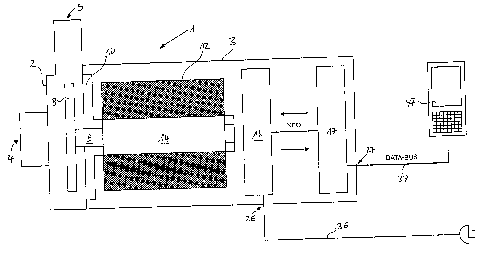
Fig. 1 schematically a pump according to the invention; and
Fig. 2 schematically the configuration of a water display device of the
conventional type and, in contrast to this, one using the pumps
-2-

CA 02599539 2007-08-30
according to the invention.
The water pump illustrated in Fig. 1 has a housing 1 which is subdivided into
a
pump housing part 2 and a motor housing part 3. The pump housing part 2
has an intake opening 4 providing the water intake and an outlet opening 5
serving as a water outlet. In the pump housing part 2 an impeller 8 is
arranged
on a rotatable shaft 9. The shaft 9 extends from the pump housing 2 into the
motor housing part 3 and into the EC motor provided therein. The EC motor
has a rotor 14 fixedly connected to shaft 9 and a stator 12 surrounding it.
Preferably, the rotor 14 is of a two-pole configuration and the stator 12 is
of a
six-pole configuration (or of a two-pole configuration with protective extra-
low
voltage). This enhances in an optimal cost/benefit ratio the control and
governing dynamics of the pump to be described in the following. The shaft 9
is supported in an end shield 10 that shields the motor mechanically relative
to the pump housing part 2 and the impeller 8.
Control and governing electronics are also provided in the housing 1 and
preferably arranged also in the motor housing part 3 and thus spaced from the
water-conveying parts. The control and governing electronics can be potted
water-tightly for safety reasons. This holds true also for the stator 12 of
the
motor. Inasmuch as stator 12 and rotor 14 are separated from one another by
a so-called split cage, preferably the entire free motor housing part can be
potted in a water-tight way.
In the embodiment illustrated in Fig. 1 the entire power electronics 16 that
also comprises the pure control electronics of the pump is arranged on a first
circuit board that is proximal to the motor. Arranged on a circuit board 17
that
is positioned behind the first circuit board are the governing electronics
with
microprocessor and data storage device as well as, in the illustrated
embodiment, a BUS control module that receives data BUS signals sent from
outside the pump to the pump and converts these data to activity of the pump.
Between the two circuit boards 16 and 17 mutual information exchange takes
place within the pump. The pump is provided with an electric power input 26
-3-

CA 02599539 2007-08-30
and a control line input 27 that is independent from the input 26 and through
which the control information is supplied. An electric cable 36 beginning at
the
electric power input 26 exits from the pump housing 1 while a control data
cable 37 connects a control panel 47 to the control input 27. Of course, the
two cables 36, 37 can extend within a common casing; however, preferably
they are separate from one another in a visually recognizable way so that
wrong connections are prevented.
In Fig. 2, the upper left area shows a water display device or fountain device
of the conventional type. Several jets 50 are controlled by means of their own
proportional valve 51 and their own electric lines 55, respectively. For this
purpose, the electric lines 55 are connected to an external control unit 57. A
central pump 53 is also connected to the external control unit 57 and is
connected through pipelines 54 to the proportional valves 51 and is always
running under full load. The proportional valves 51, controlled by the control
57, release or interrupt water flow to the jets 50.
Underneath a new water display device or fountain device is illustrated that
has several pumps 33 according to the invention. They are connected to a
common control device in the form of control panel 47. The device has the
same number of jets 50 as the conventional device. In contrast to the upper
device, in the device according to the invention however each nozzle 50 has
correlated therewith its own pump 33. The pumps are connected by control
cables 37 to the control panel 47. Even though other control systems are
possible, in this connection particularly a standardized BUS system with
digital signal transmission is especially preferred. As illustrated, the pumps
33
can be connected to the control panel 47 by means of electric or electronic
serial connection.
While in the conventional system a complex control 57 from the exterior is
required, in the new system the complete intelligence is residing in the pumps
33, respectively. Wiring expenditure is teduced to a minimum and complex
piping is not needed at all. Moreover, pumps with EC motors can be produced
-4-

CA 02599539 2007-08-30
inexpensively and have a high efficiency that reduces the running costs. The
energy consumption for the novel device is proportional approximately to the
speed that is demanded, in accordance with the water flow rate. For
example, the conventional device illustrated at the top would have a power
input three times as high as a comparable novel device.
The pumps 33 according to the invention have excellent control and
governing dynamics enabling a precise control of the pump 33 and thus
unexpected effects. The control behavior in the lower range is as precise as
in the upper range. This control behavior cannot be achieved with
conventional technology.
-5-

Dessin représentatif
Une figure unique qui représente un dessin illustrant l'invention.
États administratifs

2024-08-01 : Dans le cadre de la transition vers les Brevets de nouvelle génération (BNG), la base de données sur les brevets canadiens (BDBC) contient désormais un Historique d'événement plus détaillé, qui reproduit le Journal des événements de notre nouvelle solution interne.

Veuillez noter que les événements débutant par « Inactive : » se réfèrent à des événements qui ne sont plus utilisés dans notre nouvelle solution interne.

Pour une meilleure compréhension de l'état de la demande ou brevet qui figure sur cette page, la rubrique Mise en garde , et les descriptions de Brevet , Historique d'événement , Taxes périodiques et Historique des paiements devraient être consultées.

Historique d'événement

Description Date
Demande non rétablie avant l'échéance 2012-08-30
Le délai pour l'annulation est expiré 2012-08-30
Réputée abandonnée - omission de répondre à un avis sur les taxes pour le maintien en état 2011-08-30
Modification reçue - modification volontaire 2008-08-20
Demande publiée (accessible au public) 2008-03-01
Inactive : Page couverture publiée 2008-02-29
Inactive : CIB attribuée 2008-02-20
Inactive : CIB en 1re position 2008-02-20
Lettre envoyée 2007-11-22
Modification reçue - modification volontaire 2007-10-18
Inactive : Transfert individuel 2007-10-18
Inactive : Déclaration des droits - Formalités 2007-10-18
Demande reçue - nationale ordinaire 2007-10-03
Inactive : Certificat de dépôt - Sans RE (Anglais) 2007-10-03

Historique d'abandonnement

Date d'abandonnement Raison Date de rétablissement
2011-08-30

Taxes périodiques

Le dernier paiement a été reçu le 2010-06-28

Avis : Si le paiement en totalité n'a pas été reçu au plus tard à la date indiquée, une taxe supplémentaire peut être imposée, soit une des taxes suivantes :

  • taxe de rétablissement ;
  • taxe pour paiement en souffrance ; ou
  • taxe additionnelle pour le renversement d'une péremption réputée.

Les taxes sur les brevets sont ajustées au 1er janvier de chaque année. Les montants ci-dessus sont les montants actuels s'ils sont reçus au plus tard le 31 décembre de l'année en cours.
Veuillez vous référer à la page web des taxes sur les brevets de l'OPIC pour voir tous les montants actuels des taxes.

Historique des taxes

Type de taxes Anniversaire Échéance Date payée
Taxe pour le dépôt - générale 2007-08-30
Enregistrement d'un document 2007-10-18
TM (demande, 2e anniv.) - générale 02 2009-08-31 2009-06-12
TM (demande, 3e anniv.) - générale 03 2010-08-30 2010-06-28
Titulaires au dossier

Les titulaires actuels et antérieures au dossier sont affichés en ordre alphabétique.

Titulaires actuels au dossier
OASE GMBH
Titulaires antérieures au dossier
ANDREAS HANKE
HERBERT LAMBERS
Les propriétaires antérieurs qui ne figurent pas dans la liste des « Propriétaires au dossier » apparaîtront dans d'autres documents au dossier.
Documents

Pour visionner les fichiers sélectionnés, entrer le code reCAPTCHA :


Pour visualiser une image, cliquer sur un lien dans la colonne description du document (Temporairement non-disponible). Pour télécharger l'image (les images), cliquer l'une ou plusieurs cases à cocher dans la première colonne et ensuite cliquer sur le bouton "Télécharger sélection en format PDF (archive Zip)" ou le bouton "Télécharger sélection (en un fichier PDF fusionné)".

Liste des documents de brevet publiés et non publiés sur la BDBC .

Si vous avez des difficultés à accéder au contenu, veuillez communiquer avec le Centre de services à la clientèle au 1-866-997-1936, ou envoyer un courriel au Centre de service à la clientèle de l'OPIC.

({010=Tous les documents, 020=Au moment du dépôt, 030=Au moment de la mise à la disponibilité du public, 040=À la délivrance, 050=Examen, 060=Correspondance reçue, 070=Divers, 080=Correspondance envoyée, 090=Paiement})


Description du
Document 
Date
(aaaa-mm-jj) 
Nombre de pages   Taille de l'image (Ko) 
Description 2007-08-29 5 214
Abrégé 2007-08-29 1 21
Revendications 2007-08-29 2 59
Dessins 2007-08-29 2 48
Dessin représentatif 2008-02-06 1 21
Certificat de dépôt (anglais) 2007-10-02 1 169
Courtoisie - Certificat d'enregistrement (document(s) connexe(s)) 2007-11-21 1 104
Rappel de taxe de maintien due 2009-05-03 1 111
Courtoisie - Lettre d'abandon (taxe de maintien en état) 2011-10-24 1 173
Rappel - requête d'examen 2012-04-30 1 118
Correspondance 2007-10-02 1 13
Correspondance 2007-10-17 2 34
Correspondance de la poursuite 2007-10-17 1 34