Note : Les descriptions sont présentées dans la langue officielle dans laquelle elles ont été soumises.
CA 02600752 2007-09-11
WO 2006/130089 PCT/SE2006/000654
Arrangement for the treatment of cellulose pulp in a washing
apparatus arranged with a reinforcing frame.
The present invention relates to a washing apparatus for
washing of cellulose pulp.
In all fibre lines, some kind of washing equipment for
separating the liquor of the digestion from the pulp is
included. Washing equipment is included later on in the
process for separation of bleach liquors after bleaching
stages. There are a number of different kinds of washing
equipments operating according to various principles.
One well-known kind of washing apparatus is the drum
washer where the pulp is dewatered on a rotatable filter
drum after addition of washing liquid that displaces the
liquor remaining in the pulp web after preceding process
stages, e.g. a digestion stage or bleaching stage. The
static pressure causes the displaced liquid to pass
through a perforated metal sheet arranged on the rotatable
drum. A further development of the original drum washer is
the pressurized displacement washer, where the filtrate at
overpressure is caused to pass through the metal sheet.
The increase in the pressure difference results in an
improved dewatering of the pulp. In the pressurized
displacement washer, the increase in pressure difference
may result in that the pulp web gets stuck harder towards
the metal sheet of the drum and sometimes has to be
removed by some kind of aid. Then, the pulp web can be
unfastened for example by means of liquid or air.
According to a known design of a pressurized displacement
washer, the drum is provided with compartments in which
the pulp locates itself in long and narrow rectangles
towards the metal sheet in the axial direction of the
CA 02600752 2007-09-11
WO 2006/130089 PCT/SE2006/000654
2
drum. The subdivision in compartments of the drum ensures
that the pulp cake does not break up and moves, but
instead maintains the form produced at application on the
pulp. The compartments are made up of compartment walls
arranged axially along the whole axle of the drum. The
perforated metal sheet, on which the pulp deposits, is
located on a distance from the axle of the drum such that
filtrate channels are formed in the space between the drum
and the metal sheet. Thus, there are at least as many
filtrate compartments as pulp compartments along the
circumference of the drum. In a drum washer, a number of
various washing stages can be carried out, with separate
addition of washing liquid to the various stages and also
return of filtrate from a stage as washing liquid to
another.
In order to maintain maximal washing efficiency, it is
desirable to assure that washing liquid intended for a
specific washing stage not is transferred to a subsequent
washing stage. A pressure difference between the stages
results in that added washing liquid strives for moving
itself towards the lower pressure. For the purpose of
being able to separate different washing stages, that are
carried out in one washing zone on the drum, and also
formation stage, that is carried out in a formation zone
on the drum, and discharge stage (increased pulp
concentration zone forms a first part of the discharge
zone), that is carried out in a discharge zone on the
drum, the respective zones are sealed with axial seals.
The axial seals are located between the rotating drum and
the surrounding casing. The filtrates from the zones,
respectively, are separated by seals in a peripheral end
valve arranged at one or both of the gables of the drum.
CA 02600752 2007-09-11
WO 2006/130089 PCT/SE2006/000654
3
Known washing apparatuses for washing of paper pulp, which
are based on the principle of counter-current washing with
compartmented drum, have a relatively high dead weight.
The reason is that the axial seals, between atmospheric
and pressurized spaces, as well as between washing zones,
are extremely sensitive for geometrical deviations. It is
of the utmost importance for the function of the washing
apparatus that the gap between a seal and the drum is
reduce to a minimum and is kept constant. If that is not
the case, leakage of filtrate arises either between
washing zones or to spaces that are not pressurized. The
geometrical deviations originate above all due to the
internal overpressure that is utilized at washing. For the
purpose of minimising the deformation, and by that
increasing the efficiency and the functionality of the
washing apparatus, the supporting structure on existing
washing apparatuses is very heavy and solid, since it is
composed of a strong framework arranged outside the
surrounding casing that encloses the pressurized space.
These frameworks in known washing apparatuses comprises a
number of heavy duty beams in the longitudinal direction
of the casing, axially the drum, and a plurality of solid
stiffening metal sheets arranged at the upper part of the
washing apparatus. High weight means high cost of
production owing to large consumption of material and
complicated operations at manufacture. The high dead
weight also presents a problem when setting up the washing
apparatus. A large overhead travelling crane capacity is
required, the transportations becomes more difficult and
increase in prices, and also very heavy foundations and
supporting cables are required in buildings in order to
manage the high dead weight.
CA 02600752 2013-07-08
23808-207
4
Some embodiments of the present invention may achieve an
improved washing apparatus where at least partly the drawbacks
associated with what is previously known, according to the
state of the art, can be eliminated. Some embodiments of the
present invention may provide a washing apparatus that
minimises the deformation in the pressurised part of the
washing apparatus and at the same time has a lowered dead
weight compared to known washing apparatuses according to the
state of the art, and also a washing apparatus that can be
manufactured cost-efficiently and in a labour-saving way.
According to one embodiment of the present invention there is
provided a washing apparatus for washing of cellulose pulp.
The washing apparatus comprises: a rotatable drum, provided
with a number of outer compartments for the paper pulp to be
washed, which compartments are defined by axial compartment
walls and distributed along the circumference of the drum; a
stationary support having two opposite transverse beams,
whereby the drum extends between the transverse beams and is
rotatably journalled on both of the transverse beams of the
support; a stationary cylindrical casing, having two opposite
gables, that encloses the drum, whereby an annular space is
defined between the casing and the drum; a number of seals that
are arranged on the casing and that seals between the casing
and the compartment walls of the compartments, such that the
annular space is divided in a formation zone for forming of the
pulp in the compartments of the drum, at least one washing zone
for washing of the formed pulp at overpressure, and a discharge
zone for discharge of the washed pulp from the annular space;
and at least a reinforcing frame rib, that is attached to the
casing between the gables, wherein the reinforcing frame rib
extends around the entire casing
CA 02600752 2007-09-11
WO 2006/130089 PCT/SE2006/000654
for fixing the casing in a predetermined form, whereby
detrimental deformation of the casing when washing the
paper pulp in the pressurized spaces is prevented, and
that the casing forms a longitudinal discharge opening,
5 relatively the axial extension of the drum, for washed
pulp that is discharged from the discharge zone, and where
the reinforcing frame rib extends straight across the
discharge opening of the casing.
Thanks to the configuration with an "encircling" frame rib
that extends around the entire casing, the heavy load-
bearing structures in the shape of heavy frameworks,
having a plurality of heavy metal sheets and beams in
known washing apparatuses according to the state of the
art, can be eliminated to a great extent. A considerable
lower dead weight and a more simple construction of the
washing apparatus according to the present invention can
be obtained compared to known washing apparatuses.
Altogether, the construction is permitted to have a
considerable lower dead weight but with a maintained
function than a corresponding washing apparatus according
to the state of the art. A washing apparatus according to
the present invention results in a better utilization of
material, since the same small deformations can be
obtained as with washing apparatuses according to the
state of the art, but with less consumption of material.
The reinforcing frame rib extents around the entire
casing, but need not to be arranged without interruption
around the casing, but can preferably be divided in
sections that are fixed to each other, e.g. with screw
joint reinforcement. Suitably the frame rib is divided in
two sections, one upper section that extends around the
upper half around the casing and a lower section that
CA 02600752 2007-09-11
WO 2006/130089 PCT/SE2006/000654
6
extends around the lower section of the casing. The drum
may suitably be provided with at least an outer encircling
ring, that extends in the circumferential direction of the
drum and is located axially opposed to the reinforcing
frame rib in order to avoid built up of pulp on the frame
rib at the discharge opening. The purpose of the ring is
to prevent that pulp is allowed to be formed in the
portion of the compartment that corresponds to the axial
position of the reinforcing frame rib. If the frame rib is
divided in several sections, such as an upper and a lower
section, the lower section extends straight across the
discharge opening of the casing.
Advantageously, it can be sufficient to only utilize one
single reinforcing frame rib, although if, within the
scope of the invention in its most general extent, it is
not excluded to use more than one frame rib. An advantage
by the preferred embodiment to utilize only one
reinforcing frame rib is that an above mentioned
longitudinal discharge opening in the casing for discharge
of washed pulp, which discharge opening extends relatively
the axial extension of the drum, only becomes blocked over
one single position where the single frame rib passes
across the discharge opening.
According to yet a preferred embodiment, the casing may
have a number of oblong openings that extends axially
relatively the drum, the seals are arranged in the
openings, and the reinforced frame rib extends straight
across the oblong openings of the casing. Preferably,
stiffened wall portions can be fixed between the gables
and the frame rib along and adjacent to the openings.
CA 02600752 2007-09-11
WO 2006/130089 PCT/SE2006/000654
7
The present invention will now be described more in detail
in embodiments, with reference to the attached drawings,
without limiting the interpretation of the invention
thereto, in which
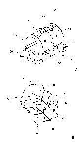
Fig. 1A schematically shows, in a perspective view
obliquely from above, a support with a casing to a washing
apparatus according to an embodiment of the present
invention,
Fig. 1B schematically shows, in a perspective view
obliquely from below, the support and the casing according
to Fig. 1A,
Fig. 2 schematically shows, in a perspective view
obliquely from above, a drum according to an embodiment of
the present invention, intended to be journalled on the
support according to Figs. 1A-B,
Fig. 3 schematically shows, in an explanatory sketch, a
cross-section A-A through a washing apparatus according to
an embodiment of the present invention, where the drum in
Fig. 2 is arranged in the support shown in Figs. 1A-B.
The same reference numerals have been used for
corresponding features in the different embodiments shown
in Figs. 1-3.
Figs. 1A-B and Fig. 2 shows separate main components of a
washing apparatus for washing of cellulose pulp, according
to the pressurized displacement washer kind. The washing
apparatus comprises a rotatable drum 2, provided with a
number of outer compartments 4, having a bottom 6 of
perforated metal sheet, in which compartments the paper
CA 02600752 2007-09-11
WO 2006/130089 PCT/SE2006/000654
8
pulp to be washed is placed during feeding on the drum.
The compartments 4 are defined by compartment walls 8
arranged axially along the entire axle 10 of the drum and
distributed along the circumference 12 of the drum. The
washing apparatus comprises a stationary support 14 having
two opposite transverse beams 16. The drum 2 extends
between the transverse beams and is rotatably journalled
on the both transverse beams 16 of the support. A
stationary cylindrical casing 18, having two opposite
gables 19, encloses the drum 2, whereby an annular space
(see Fig. 3) is defined between the casing 18 and the
drum 2.
Washing liquid is supplied to the annular space 20 and, at
15 overpressure, the filtrate is caused to pass the
perforated metal sheet that forms the bottom 6 in the pulp
compartments 4 on the drum 2. The increase in pressure
difference results in an improved dewatering of the pulp.
The pulp locates itself in the compartments 4 on the drum
20 in long and narrow rectangles towards the metal sheet in
the axial direction of the drum. The subdivision in
compartments of the drum ensures that the pulp cake does
not break up and moves, but instead maintains the form
produced at application on the pulp. The perforated metal
sheet, on which the pulp deposits, is located on a
distance from the axle 10 of the drum such that filtrate
channels (not shown) are formed in the space between the
drum 2 and the perforated metal sheet. Thus, along the
circumference 12 of the drum, there are at least as many
filtrate compartments as pulp compartments 4. In a drum
washer, several washing stages can be carried out, with
separate addition of washing liquid to the various stages
and also return of filtrate from one stage as washing
liquid to another stage.
CA 02600752 2007-09-11
WO 2006/130089 PCT/SE2006/000654
9
In order to maintain maximum washing efficiency, it is
desirable to assure that washing liquid intended for a
specific washing stage not is transferred to a subsequent
washing stage. A pressure difference between the stages
results in that added washing liquid aims for moving
towards the lower pressure. For the purpose of being able
to separate different washing stages Tl, T2, and also
formation stage F and discharge stage U, the respective
zones are sealed with axial seals 22. The axial seals are
positioned between the rotating drum 2 and the surrounding
casing 18. The filtrates from the respective stages are
separated by seals in a peripheral end valve arranged at
one or both gables of the drum. As evident from Fig. 3,
the washing apparatus comprises several seals 22 arranged
on the casing 18 and that seals between the casing and the
compartment walls 8 of the compartments, such that the
annular space 20 is divided in a formation zone F for
forming of the pulp in the compartments of the drum 4,
during rotation of the drum in clockwise direction R, a
first washing zone T1 and a second washing zone T2 for
washing of the formed pulp at overpressure, and a
discharge zone U for discharge of the washed pulp via a
discharge opening 26 from the annular space. Pulp to be
washed is fed in the formation zone via the inlet opening
27. In the pressurized displacement washer, the increase
in pressure difference may result in that the pulp web
gets stuck harder towards the metal sheet of the drum and
sometimes has to be removed by some kind of aid. Then, the
pulp web can e.g. be unfastened by means of liquid or air.
Again with reference to Figs. 1A-B, the washing apparatus
comprises at least a reinforced frame rib 24, which is
attached to the casing 18 between the gables 19. According
CA 02600752 2007-09-11
WO 2006/130089 PCT/SE2006/000654
to the invention, the reinforced frame rib 24 extends
around the entire casing 18 for fixing the casing in a
predetermined form, whereby detrimental deformation of the
casing, when washing the paper pulp at overpressure in the
5 pressurized spaces, can be prevented. In the case the
washing apparatus only comprises one reinforcing frame
rib, the frame rib is suitably arranged in the axial
centre C of the washing apparatus. If the washing
apparatus has a large length/diameter proportion, several
10 frame ribs can be used, which then are positioned
symmetrically around the centre C of the washing
apparatus. The purpose is to achieve an equally large
deformation on each side of the reinforcing frame rib,
that will arise due to the internal overpressure.
Again with reference to Fig. 3, an overpressure in the
formation zone F and the washing zones Tl, T2 results in
that the attachments for the longitudinal seals 22 will be
deformed and moved away from its nominal positions. Such a
movement is lowered in an effective way by the reinforcing
frame rib 24 around the entire casing 18.
As evident from Fig. 1B, the casing forms a longitudinal
discharge opening 26, relatively the axial extension of
the drum, for washed pulp that is discharged from the
discharge zone U, and the reinforcing frame rib 24 extends
straight across the discharge opening 26 of the casing. In
that respect, the drum 2 may suitably be provided with at
least an encircling ring 28, as is evident from Fig. 2,
that extends in the circumferential direction of the drum
2 and is located axially opposed to the reinforcing frame
rib 24 of the casing 18. The function of the ring 28 is to
eliminate that the pulp cake in the discharge zone U ends
up between the drum 2 and the frame rib 24 during
CA 02600752 2007-09-11
WO 2006/130089 PCT/SE2006/000654
11
discharge of the compartments 4. In case the washing
apparatus comprises several reinforcing frame ribs 24, the
drum can preferably be provided with corresponding number
of rings 28, which then are positioned axially opposed to
the frame ribs.
Furthermore, the casing may preferably as evident from
Figs. 1A-B have a number of oblong openings 30 that
extends axially relatively the drum 2. The seals 22 are
arranged in the openings 30, and the reinforced frame rib
24 extends straight across the oblong openings 30 of the
casing. In this respect, stiffened wall portions 32 can be
fixed between the gables 16 and the frame rib 24 along and
adjacent to the openings 30. These stiffened wall portions
32, along the openings 30 in which the seals 22 are to be
placed, are fixed by means of the reinforcing frame rib 24
around the casing 18 and the function of the washing
apparatus is maintained, and by that, the risk for an
altered geometrical position of the seals 22 is minimized.
The frame rib 24 can also be divided in sections that are
fixed to each other according to a not shown embodiment.
In that respect, the frame rib is suitably divided in two
sections, one upper section 34 that extends around the
upper half around the casing 18 and a lower section 36
that extends around the lower half of the casing 18,
whereby the lower section 36 extends straight across the
discharge opening 26 of the casing. The sections 34, 36
can be fixed to each other e.g. with screw joint
reinforcement.
The casing 18, the reinforcing frame rib/ribs 24 and the
stiffened wall portions 32 are made from initially plane
metal sheet elements.