Note : Les descriptions sont présentées dans la langue officielle dans laquelle elles ont été soumises.
CA 02601193 2007-09-14
WO 2006/099601 PCT/US2006/009890
ULTRASONIC RANGING IN THE NEAR ZONE
CROSS REFERENCE TO RELATED APPLICATIONS
[0001] This application claims priority under 35 U.S.C. 119(e) of U.S.
Provisional
Patent Application Serial No. 60/662,875, filed March 16, 2005.
FIELD OF THE INVENTION
[0002] The invention is directed generally to ultrasonic ranging devices and
more
particularly to ultrasonic ranging devices for ranging in the near zone.
BACKGROUND OF THE INVENTION
[0003] An ultrasonic ranging device may be used to detect the presence of
and/or
distance to a target object, such as an object located underground or stored
in an enclosed
container. The ultrasonic ranging device typically operates by generating an
ultrasonic signal or
pulse, which may be reflected upon striking the target object. The ranging
device may listen for
the reflected ultrasonic signal, or echo signal, and measure the period
between the time the signal
is sent and the time the eclio signal is received. By measuring this time
period, the ranging
device may determine the distance between the device and the target object.
For example, the
ranging device may be placed at the top of a storage tank in order to measure
the distance from
the top of the tank to the top surface of a material in the tank. Thus, the
ranging device may be
used to determine the level of material in the tank.
[0004] Some ultrasonic ranging devices may include a tra.nsducer for both
generating
the ultrasonic signal and receiving, or detecting, an echo signal that bounces
back from the target
-1-
CA 02601193 2007-09-14
WO 2006/099601 PCT/US2006/009890
object. Such devices often have a parameter called "near zone," which may
refer to the
minimum distance that can be measured by the ranging device. In other words,
the ranging
device may not be capable of measuring the distance to a target object that is
located witliin the
near zone.
[0005] The near zone limitation may be caused by a "ringing" effect that
frequently
occurs in the transducer after it generates an ultrasonic signal or pulse.
Ringing refers to a series
of (decaying) signals that are usually generated by the transducer after an
input electrical signal
is no longer applied to the transducer. A larger input electrical signal may
increase both the
amplitude of the generated ultrasonic signal and the ringing time in the
transducer (e.g., the time
it talces the transducer to get up to 90% of maximum amplitude, or down to 10%
above zero
amplitude). Ringing in the transducer may limit the transducer's ability to
detect an echo signal
from a close target object due to signal interference (i.e., the amplitude of
the echo signal may be
smaller than that of the decaying signals). Thus, the ranging device may be
incapable of both
detecting the presence of and determining the distance to the target object,
thereby limiting the
utility of the ranging device. Therefore, a need exists for an ultrasonic
ranging device that
overcomes these difficulties to permit ultrasonic ranging in the near zone.
SUMMARY OF THE INVENTION
[0006] The described embodiments contemplate a device and method for
ultrasonic
ranging in the near zone. In one embodiment, the device may include a
transducer for generating
an ultrasonic signal and for detecting an echo signal. The device may also
include a processor
for calculating the distance to a target object based on a first time period
defined by a first set of
ultrasonic signals wlien the target object is located outside the near zone
and a second time
period defined by a second set of ultrasonic signals when the target object is
located within the
near zone. In another enibodiment, the device may include a transducer and a
processor for
adjusting the amplitude of the generated ultrasonic signal until a first echo
signal is detected at
the transducer. The processor may calculate the distance to the target object
based on a time
period between the generated ultrasonic signal and the first echo signal.
[0007] The method may include generating an ultrasonic signal, detecting a
first echo
signal, determining a first time period defined by the generated ultrasonic
signal and the first
echo signal, and comparing the first time period to a second predetermined
time period. If the
first time period is less than the second predetermined time period, then
detecting at least one
additional echo signal, determining a third time period defined by consecutive
echo signals,
comparing the first time period with the third time period, and calculating
the distance to the
target object using a time period based on the comparison result.
-2-
CA 02601193 2007-09-14
WO 2006/099601 PCT/US2006/009890
[0008] This Summary is provided to introduce a selection of concepts in a
simplified
form that are further described below in the Detailed Description. This
Summary is not intended
to identify key features or essential features of the claimed subject matter,
nor is it intended to be
used as an aid in detennining the scope of the claimed subject matter.
BRIEF DESCRIPTION OF THE DRAWINGS
[0009] The foregoing summary, as well as the following detailed description of
preferred embodiments, is better understood when read in conjunction with the
appended
drawings. For the purposes of illustration, there is shown in the drawings
exemplary
embodiments; however, the invention is not limited to the specific methods and
instrumentalities
disclosed. In the drawings:
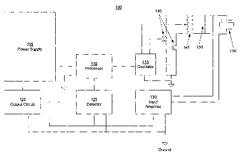
[0010] Figure 1A is a block diagram of an ultrasonic ranging device, in
accordance
with a.n embodiment;
[0011] Figure 1B is a block diagram of an ultrasonic ranging device, in
accordance with
an alternative embodiment;
[0012] Figure 2A is an exainple signal plot of amplitude versus time
illustrating a
generated ultrasonic signal and corresponding return echo signals from a
target object located
outside of a near zone;
[0013] Figure 2B is an example signal plot of amplitude versus time
illustrating a
generated ultrasonic signal and corresponding return echo signals from a
target object located
within a near zone;
[0014] Figures 3A and 3B are example signal plots of amplitude versus time
illustrating
the relationship between the amplitude of a generated ultrasonic signal and
ringing duration;
[0015] Figure 4 is a flow diagram illustrating an example method of ultrasonic
ranging
in the near zone; and
[0016] Figure 5 is a flow diagram illustrating an alternative example method
of
ultrasonic ranging in the near zone.
DETAILED DESCRIPTION OF ILLUSTRATIVE EMBODIMENTS
[0017] The subject matter of the described embodiments is described with
specificity to
meet statutory requirements. However, the description itself is not intended
to limit the scope of
this patent. Rather, the inventor has contemplated that the claimed subject
matter might also be
embodied in other ways, to include different steps or elements similar to the
ones described in
this document, in conjunction with other present or future technologies.
Moreover, although the
term "step" may be used herein to connote different aspects of methods
employed, the term
-3-
CA 02601193 2007-09-14
WO 2006/099601 PCT/US2006/009890
should not be interpreted as implying any particular order among or between
various steps herein
disclosed unless and except when the order of individual steps is explicitly
described.
[0018] Ultrasonic ranging devices typically include components for generating
and
detecting ultrasonic signals and for determining the time period defined by a
set of ultrasonic
signals. The time period defined by a set of ultrasonic signals may be related
to the distance
between the ranging device and a target object. Conventional ultrasonic
ranging devices often
have difficulty measuring the distance to the target object when the target
object is within a
certain area lcnown as the "near zone." Generally, a ranging device's
inability to measure
distances in the near zone may be caused by the ringing of a transducer in the
ranging device that
may be used to generate ultrasonic signals. That is, the transducer may be
unable to detect
reflected ultrasonic signals, or echo signals, because the decaying generated
ultrasonic signals
may be larger than the return echo signals. The ratio of the generated
ultrasonic signal and the
expected return echo signal for a given distance may be one of the factors
that detennine the near
zone limit of an ultrasonic ranging device. Typically, an ultrasonic ranging
device with a longer
range may also have a larger near zone as a result of an increase in the
amplitude, or energy, of
the generated ultrasonic signal.
[0019] Figure 1A is a block diagram of an ultrasonic ranging device for
ultrasonic
ranging in the near zone, according to an embodiment. Ultrasonic ranging
device 100 may
calculate the distance to a target object based on a first time period defined
by a generated
ultrasonic signal and a first echo signal when the target object (e.g., the
top surface of material in
a tank) is far from the transducer and may calculate the distance to the
target object based on a
second time period defined by a first echo signal and a second echo signal (or
by subsequent sets
of echo signals) when the target is close to ranging device 100.
[0020] Ultrasonic ranging device 100 may include power supply 105, processor
110,
oscillator 115, output circuit 120, detector 125, input amplifier 130,
transducer 135, output
amplifiers 140, transformer 145 and capacitor 150. Power supply 105 may
include one or more
power supply units, which may be powered via any suitable input supply (not
shown in Figure
1A). For example, the input supply may be an AC line voltage (e.g., 120 VAC)
or a DC line
voltage (e.g., 24 VDC). Power supply 105 may have one or more outputs. For
example, as
shown in Figure lA, the output voltages of power supply 105 may be fed to
multiple components
within ultrasonic ranging device 100, such as processor 110, oscillator 115,
detector 125, input
amplifier 130, etc. Each output of power supply 105 may consist of a different
output voltage
(e.g., +3V for processor related circuits and +10 V for amplifier and detector
related circuits).
-4-
CA 02601193 2007-09-14
WO 2006/099601 PCT/US2006/009890
[0021] Processor 110 may be connected to oscillator 115, which may be any
suitable
circuit or device for generating recurring waveforms (i.e., electrical
signals). Processor 110 may
be any suitable processor containing executable instructions for causing
oscillator 115 to
generate an electrical signal and for calculating the distance between ranging
device 100 and a
target object based on the time periods between ultrasonic signals and/or
electrical signals. For
example, processor 110 may initiate a ping voltage, which may cause oscillator
115 to generate
an electrical signal. The electrical signal may be of any suitable amplitude
and/or frequency.
The electrical signal generated by oscillator 115 may be amplified via output
amplifiers 140.
The output of output amplifiers 140 may then be fed to the primary side of
transfoimer 145,
which may be any suitable transformer for stepping-up the amplitude of an
input electrical
signal. The stepped-up electrical signal at the secondary side of transformer
145 may be applied
across both capacitor 150 and transducer 135, which may be a.ny suitable
circuit or device for
generating ultrasonic signals from electrical signals and vice versa.
[0022] Transducer 135 may receive the stepped-up electrical signal at the
secondary
side of transformer 145 and generate an ultrasonic signal with a predetermined
amplitude. The
frequency of the generated ultrasonic signal may be beyond the range of human
hearing (e.g., at
least 20 kHz). The generated ultrasonic signal may be transmitted, or
directed, towards to a
target object. Transducer 135 may continue to "ring" (i.e., generate an
ultrasonic signal) for a
certaiii period of time even after power is removed from transformer 145.
Thus, transducer 135
may not be able to detect reflected ultrasonic signals, or echo signals,
during the ringing time as
a result of signal interference with the generated ultrasonic signal.
[0023] Upon reaclling the target object, some or all of the generated
ultrasonic signal
may be reflected, creating a first reflected ultrasonic signal, or first echo
signal, that may travel
baclc towards ranging device 100. Some or all of the first echo signal may
then reflect from
ranging device 100 and travel back towards the target object. Upon reaching
the target object,
some or all of the first echo signal may reflect from the target object,
creating a second echo
signal that may travel back towards ranging device 100. Some or all of the
second echo signal
may then reflect from ranging device 100 and travel back towards the target
object. Upon
reaching the target object, some or all of the second echo signal may reflect
from the target
object, creating a third echo signal that may travel baclc towards ranging
device 100. The
ainplitude of each subsequent echo signal may decrease, or decay. Thus, this
process may
continue until the amplitude of subsequent echo signals eventually reaches a
level that is not
detectable by ranging device 100. Each reflected ultrasonic signal, or echo
signal, may be
detected by transducer 135, which may generate a corresponding electrical
signal. Thus,
-5-
CA 02601193 2007-09-14
WO 2006/099601 PCT/US2006/009890
transducer 135 may generate a first electrical signal based on the first echo
signal, a second
electrical signal based on the second echo signal, a tlZird electrical signal
based on the third echo
signal, and so forth.
[0024] Processor 110 may also be connected to detector 125, whicli may be
comiected
to transducer 135 via input amplifier 130. Detector 125 may include any
suitable circuit or
device for filtering and/or level shifting electrical signals received from
input amplifier 130. As
shown in Figure 1A, electrical signals from transducer 135 may be fed to input
amplifier 130,
which may include one or more amplifiers for amplifying the electrical
signals. Detector 125
may then receive the amplified electrical signals and perform any necessary
filtering and/or level
shifting. The output of detector 125 may then be fed to processor 110, which
may determine the
distance to a target object based on the time period defined by one or more
sets of electrical
signals received from detector 125. Accordingly, each set of electrical
signals received from
detector 125 may correspond to a respective set of ultrasonic signals detected
at transducer 135.
[0025] For example, a time period defined by a given set of electrical signals
may
correspond to the time it talces for the generated ultrasonic signal to travel
to a target object and
reflect back to ranging device 100. The speed of the ultrasonic signal to and
from the target
object may remain constant. Thus, the distance to the target object may be
calculated by
dividing the time period approximately in half and multiplying the result by
the speed of the
ultrasonic signal, which may be approxiinately equal to the speed of sound. It
will be
appreciated that the value for the speed of sound in the distance calculation
may be adjusted to
compensate for certain enviromnental factors, such as temperature,
transmission medium,
humidity, and the like.
[0026] In order to measure the distance to a target object that is located
either inside or
outside the near zone, processor 110 may measure a first time period defined
by the generated
ultrasonic signal and the first echo signal, which may correspond to a first
detected echo signal.
Processor 110 may then determine whether the first time period is greater than
or equal to a
second predetermined time period, which may represent a threshold at which the
target object is
deeined to be sufficiently beyond the near zone of ranging device 100. If the
first time period is
greater than or equal to the second predetermined time period, processor 110
may calculate the
distance to the target object based on the first time period. If the first
time period is less than the
second predetermined time period, processor may wait for at least one
additional echo signal,
which may correspond to a second detected echo signal. Processor 110 may then
measure a third
time period defined by consecutive echo signals. It will be appreciated that
the third time period
may be defmed by any two consecutive echo signals that are detected after the
generated
-6-
CA 02601193 2007-09-14
WO 2006/099601 PCT/US2006/009890
ultrasonic signal (e.g., first and second detected echo signals, second and
third detected echo
signals, third and fourtli detected echo signals, and so forth).
[0027] Processor 110 may then compare the first and third time periods. If the
first
time period is substantially equal to the third time period, the target object
may be outside of the
near zone and processor 110 may calculate the distance to the target object
based on either the
first time period or the third time period. If the first time period is at
least two times greater than
the third time period, the target object may be located within the near zone
and processor 110
may calculate the distance to the target object based on the third time
period.
[0028] The distance calculated by processor 110 may then be fed to output
circuit 120,
which may be any suitable circuit or device for conveying and/or processing
the distance
information. For example, output circuit 120 may be an analog indicator, a
digital indicator,
and/or a series of relays configured to actuate upon a predetermined measured
distance (e.g.,
configured to sllut-off a pump when material in a tanlc reaches a
predeterinined level). In
addition, output circuit 120 may be any suitable circuit or device for
transmitting the distance
information to a remote control system. For example, output circuit 120 may
transmit the
distance information via a 4-20 mA loop or via a digital interface (e.g., Hart
protocol, Ethernet).
[0029] In an alternative embodiment, ultrasonic ranging device 100 may
generate an
ultrasonic signal with a lower amplitude when a target object is near ranging
device 100 (e.g.,
within the near zone) and may generate an ultrasonic signal with a higher
amplitude when the
target object is farther away from ranging device 100 (e.g., outside of the
near zone). In this
manner, echo signals from the target object may be more usable (i.e., more
easily detectable).
For example, as the distance between the target object and ranging device 100
is reduced, the
amplitude of the generated ultrasonic signal may be reduced because the
ultrasonic signal may
not have to travel a long distance. By reducing the amplitude of the generated
ultrasonic signal,
a lower ringing duration may be achieved, thereby reducing the size of the
near zone. As the
distance between the target object and ranging device 100 is increased, the
amplitude of the
generated ultrasonic signal may be increased in order to ensure that the
ultrasonic signal reaches
the target object. Any resulting increase in ringing time due to the increased
amplitude of the
generated ultrasonic signal may be inconsequential because the target object
is located
sufficiently beyond the near zone.
[0030] Figure 1B is a bloclc diagram of an exam.ple ultrasonic ranging device
for
adjusting the amplitude level of a generated ultrasonic signal. As shown in
Figure 1B, ultrasonic
ranging device 100 may also include variable power supply 105a, which may be
part of or
separate from power supply 105. The output voltage of variable power supply
105a may be
-7-
CA 02601193 2007-09-14
WO 2006/099601 PCT/US2006/009890
supplied to the primary side of transformer 145 and may be adjusted by
processor 110 via any
suitable control circuit (not shown in Figure 1B). The supply voltage to
transformer 145 may
control the step-up in amplitude between the primary and secondary sides of
transformer 145.
Thus, processor 110 may reduce the amplitude of the electrical signal at the
secondary side of
transfonner 145 by decreasing the supply voltage and may increase the
ainplitude of the
electrical signal at the secondary side of transformer 145 by increasing the
supply voltage. By
lowering the amplitude of the electrical signal at the secondary side of
transformer 145, the
ainplitude of the ultrasonic signal generated by transducer 135 may also be
reduced. Thus, the
ringing time in transducer 135 may be decreased as the amplitude of the
generated ultrasonic
signal is decreased, thereby enabling transducer 135 to detect echo signals
from target objects
that are close to ranging device 100.
[0031] Processor 110 may incrementally increase the output voltage of variable
power
supply 105a by a predetennined amount between a first and second output
voltage. The first
voltage may represent a minimum output voltage and the second output voltage
may represent a
maximuin output voltage. Thus, in order to detennine the distance to a target
object that is
located close to ranging device 100, processor 110 may adjust the output
voltage of variable
power supply 105a lower to a first output voltage and then ping oscillator 115
to generate an
electrical signal. After the ultrasonic signal is generated by transducer 135,
processor 110 may
listen for a reflected ultrasonic signal, or echo signal, for a predetermined
period of time. If an
echo signal is not received, processor 110 may incrementally increase the
output voltage and
may again ping oscillator 115. This process may be repeated until an echo
signal is detected or
until the second output voltage level is reached.
[0032] Figure 2A is an example signal plot of amplitude versus time
illustrating a
generated ultrasonic signal and corresponding return echo signals from a
target object located
outside of the near zone of ultrasonic ranging device 100. As shown in Figure
2A, generated
ultrasonic signa1205 may reflect from the target object, creating a series of
echo signals (e.g.,
echo signals 210, 215, 220, 225, 230 and 235) that may be detected at
transducer 135 in ranging
device 100. Generated ultrasonic signa1205 and echo signa1210 may define time
period 240,
echo signals 210 and 215 may define time period 245, echo signals 215 and 220
may define time
period 250, echo signals 220 and 225 may define time period 255, echo signals
225 and 230 may
define time period 260, and echo signals 230 and 235 may define time period
265. Each of the
respective time periods 240 to 265 may correspond to the time it talces for an
ultrasonic signal to
travel to and from the target object. The ultrasonic signal may travel each
direction at the same
speed (e.g., at the speed of sound). As shown in Figure 2A, each of the
respective time periods
-8-
CA 02601193 2007-09-14
WO 2006/099601 PCT/US2006/009890
240 to 265 may be the same when the target object is located outside the near
zone of ranging
device 100. Tlius, processor 110 may calculate the distance to the target
object based on any of
time periods 240 to 265.
[0033] Figure 2B is an example signal plot of ainplitude versus time
illustrating a
generated ultrasonic signal and corresponding return echo signals from a
target object located
within the near zone of ultrasonic ranging device 100. Similar to Figure 2A,
generated ultrasonic
signa12051nay reflect from the target object, creating a series of echo
signals (e.g., echo signals
210, 215, 220, 225, 230 and 235). Generated ultrasonic signa1205 and echo
signal 210 may
define time period 275, echo signals 210 and 215 may define time period 280,
echo signals 215
and 220 may define time period 285, echo signals 220 and 225 may define time
period 290, echo
signals 225 and 230 may define time period 295, and echo signals 230 and 235
may define tiine
period 297. As shown in Figure 2B, echo signa1210 may not be detected because
it overlaps
with the ultrasonic signal generated as a result of the ringing effect in
transducer 135. Thus,
processor 110 may not be capable of detennining time period 275 and,
therefore, echo signal 215
may correspond to the first detected echo signal.
[0034] As shown in Figure 2B, time period 299 may correspond to the time
period
deflned by generated ultrasonic signa1205 and echo signa1215. Time period 299
may equal the
sum of time periods 275 and 280. As noted above, the time periods defined by
consecutive
ultrasonic signals (e.g., time periods 275 to 297) may be substantially equal
because the
ultrasonic signals may travel to and from the target object at the same speed.
Thus, tiine period
299 may be approximately two times greater than time periods 275 to 297 and,
therefore, may
not represent an accurate distance to the target object. Consequently, as
noted above, processor
110 may compare time period 299 to at least one of time periods 280 to 297. If
time period 299
is two times greater, processor 110 may calculate the distance to the target
object based on any of
time periods 280 to 297. It will be appreciated that as the target object is
moved closer to
ranging device 100, additional echo signals (e.g., echo signals 215, 220, 225,
etc.) may overlap
with generated ultrasonic signa1205. Thus, the time period defined by
generated ultrasonic
signa1205 and the first detected echo signal may increase.
[0035] It will also be appreciated that time periods 240 to 265 and 275 to 297
may be
detennined in any manner that is consistent with the travel time of an
ultrasonic signal between
ranging device 100 and a target object. For example, as shown in Figure 2A,
time periods 240 to
265 may be determined by measuring the time between the leading edge of each
consecutive
ultrasonic signal. Time periods 240 to 265 may also be determined by measuring
the time
between peak amplitudes of each consecutive ultrasonic signal.
-9-
CA 02601193 2007-09-14
WO 2006/099601 PCT/US2006/009890
[0036] Figures 3A and 3B are example signal plots of amplitude versus time
illustrating
the relationship between the amplitude of a generated ultrasonic signal and
ringing duration of
transducer 135 in ranging device 100. In Figure 3A, ultrasonic signal 305 with
amplitude 330
may be generated by transducer 135 by applying supply voltage Vt (not shown in
Figttre 3A)
from variable power supply 105a to the primary side of transformer 145. Supply
voltage V1 may
be applied to transformer 145 for time period 310. As shown in Figure 3A,
transducer 135 may
continue to ring for time period 315. The sum of time periods 310 and 315 may
correspond to a
first near zone.
[0037] In Figure 3B, ultrasonic signal 305 with amplitude 335 may be generated
by
transducer 135 by applying supply voltage V2 (not shown in Figure 3B) from
variable power
supply 105a to the primary side of transformer 145. Supply voltage V2 may be
smaller than Vl
and may also be applied to transformer 145 for time period 310. As shown in
Figure 3B,
transducer 135 may continue to ring for time period 320. The sum of time
periods 310 and 320
may correspond to a second near zone. As shown in Figures 3A and 3B, amplitude
335 may be
smaller than amplitude 330. In addition, time period 320 may be smaller than
time period 315,
thereby reducing the size of the second near zone with respect to the first
near zone. Thus,
ranging device 100 may be capable of detecting a closer target object by
reducing the amplitude,
or energy, of generated ultrasonic signal 305.
[0038] Figure 4 is a flow diagram illustrating an example method of ultrasonic
ranging
in the near zone. As shown in Figure 4, at 405, an ultrasonic signal may be
generated by
ultrasonic ranging device 100 and directed towards a target object. At 410, a
first echo signal
may be detected. At 415, a first time period defined by the generated
ultrasonic signal and the
first echo signal may be determined. At 420, it may be determined whether the
first time period
is greater than or equal to a second predetermined time period, which may
represent a threshold
at which the target object is deemed to be sufficiently beyond the near zone
of ranging device
100. If the first time period is greater than or equal to the second
predetermined time period, the
process proceeds to 425. At 425, the distance to the target object is
calculated based on the first
time period. If the first time period is less than the second predetermined
time period, the
process proceeds to 430.
[0039] At 430, at least one additional echo signal may be detected by
ultrasonic ranging
device 100. At 435, a tliird time period defined by any two consecutively
detected echo signals
may be determined. At 440, the first time period may be compared with the
third time period.
At 445, it may be determined whether the first time period is substantially
equal to the third time
period. If the first time period is substantially equal to the third time
period, the process
-10-
CA 02601193 2007-09-14
WO 2006/099601 PCT/US2006/009890
proceeds to 450. At 450, the distance to the target object may be calculated
based on either the
first or tliird time periods. If the first time period is at least two times
greater than the third time
period, the process proceeds to 455. At 455, the distance to the target object
may be calculated
based on the tllird time period. As noted above, it will be appreciated that
the third time period
may be defined by any two consecutive echo signals that are detected after the
generated
ultrasonic signal.
[0040] Figure 5 is a flow diagram illustrating an alternative example method
of
ultrasonic ranging in the near zone. As shown in Figure 5; at 505, an
ultrasonic signal may be
generated by ultrasonic ranging device 100. At 510, ranging device 100 may
wait for an echo
signal for a predetermined period of time. At 515, it may be determined
whether an echo signal
is detected. If an echo signal is not detected, the process proceeds to 520.
At 520, the amplitude
of the generated ultrasonic signal may be increased. For example, as noted
above, the amplitude
of the generated ultrasonic signal may be increased by increasing the
amplitude of the input
electrical signal at transducer 135. The process may proceed back to 510,
where ranging device
100 may again wait for an echo signal for a predetermined period of time. If
an echo signal is
detected, the process may proceed to 525. At 525, a time period defined by the
generated
ultrasonic signal and the echo signal. At 530, the distance to the target
object is calculated based
on the time period.
[0041] While the embodiments have been described in connection with the
preferred
embodiments of the various figures, it is to be understood that other similar
embodiments may be
used or modifications and additions may be made to the described embodiment
for performing
the same fiuiction witllout deviating therefrom. Therefore, the disclosed
embodiments should not
be limited to any single embodiment, but rather should be construed in breadth
and scope in
accordance with the appended claims.
-11-