Sélection de la langue

Search

Sommaire du brevet 2602694 

Énoncé de désistement de responsabilité concernant l'information provenant de tiers

Une partie des informations de ce site Web a été fournie par des sources externes. Le gouvernement du Canada n'assume aucune responsabilité concernant la précision, l'actualité ou la fiabilité des informations fournies par les sources externes. Les utilisateurs qui désirent employer cette information devraient consulter directement la source des informations. Le contenu fourni par les sources externes n'est pas assujetti aux exigences sur les langues officielles, la protection des renseignements personnels et l'accessibilité.

Disponibilité de l'Abrégé et des Revendications

L'apparition de différences dans le texte et l'image des Revendications et de l'Abrégé dépend du moment auquel le document est publié. Les textes des Revendications et de l'Abrégé sont affichés :

  • lorsque la demande peut être examinée par le public;
  • lorsque le brevet est émis (délivrance).
(12) Brevet: (11) CA 2602694
(54) Titre français: LUMINAIRE D'AUVENT MODERNISE AMELIORE ET METHODE D'INSTALLATION
(54) Titre anglais: IMPROVED RETROFIT CANOPY LUMINAIRE AND INSTALLATION METHOD
Statut: Accordé et délivré
Données bibliographiques
(51) Classification internationale des brevets (CIB):
  • F21V 17/00 (2006.01)
  • F21S 08/00 (2006.01)
(72) Inventeurs :
  • KINNUNE, BRIAN L. (Etats-Unis d'Amérique)
  • GUILLIEN, WAYNE P. (Etats-Unis d'Amérique)
(73) Titulaires :
  • IDEAL INDUSTRIES LIGHTING LLC
(71) Demandeurs :
  • IDEAL INDUSTRIES LIGHTING LLC (Etats-Unis d'Amérique)
(74) Agent: SMART & BIGGAR LP
(74) Co-agent:
(45) Délivré: 2015-01-27
(22) Date de dépôt: 2007-09-18
(41) Mise à la disponibilité du public: 2008-04-06
Requête d'examen: 2012-08-13
Licence disponible: S.O.
Cédé au domaine public: S.O.
(25) Langue des documents déposés: Anglais

Traité de coopération en matière de brevets (PCT): Non

(30) Données de priorité de la demande:
Numéro de la demande Pays / territoire Date
60/850,233 (Etats-Unis d'Amérique) 2006-10-06

Abrégés

Abrégé français

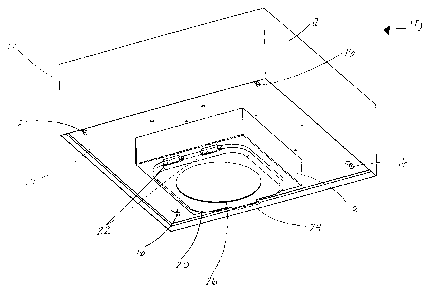
Un ensemble luminaire à monture rétrocompatible adapté pour léclairage vers le bas et comportant un boîtier pourvu de rebords orientés vers lintérieur près des bords inférieurs du boîtier. Le luminaire compte au moins deux supports fixés à au moins un des rebords, une plaque avant fixée de manière amovible aux supports du côté inférieur du boîtier ainsi quun cordon dancrage suspendu fixé à lun des supports et à la plaque avant. La plaque avant est adaptée pour retenir les composants du luminaire. Lorsque la plaque avant est retirée des supports, elle est suspendue librement par le cordon dancrage pour permettre un accès libre à lintérieur du luminaire.


Abrégé anglais

A retrofit canopy luminaire assembly adapted for downward illumination and having a housing with inwardly-directed ledges near the lower edges of the housing. The luminaire has at least two support brackets secured to at least one of the ledges; a face plate removably secured to the brackets on the lower side of the housing; and a hanging tether attached to one of the brackets and to the face plate. The face plate is adapted to hold lighting fixture components. When the face plate is removed from the brackets, the face plate hangs freely held by the tether to allow free access to the inside of the luminaire.

Revendications

Note : Les revendications sont présentées dans la langue officielle dans laquelle elles ont été soumises.


CLAIMS
1. A retrofit luminaire assembly adapted for downward illumination and
having a
housing with inwardly-directed ledges near the lower edges of the housing,
comprising:
.cndot. at least two support brackets secured to at least one of the
ledges;
.cndot. a face plate removably secured to the brackets on the lower side of
the
housing, the face plate adapted to hold lighting fixture components; and
.cndot. first and second hanging tethers each attached at its proximal end
to a
separate one of the support brackets along one side of the housing, the first
and second tethers being secured at their distal ends to opposite ends of one
side of the faceplate,
wherein when the face plate is removed from the brackets, the face plate hangs
freely held by the tethers to allow free access to the inside of the
luminaire.
2. A method of installing a retrofit luminaire assembly adapted for
downward
illumination and having a housing with inwardly-directed ledges near the lower
edges of
the housing, the method comprising the steps of:
.cndot. providing at least two support brackets;
.cndot. securing the two support brackets to at least one ledge;
.cndot. providing a face plate adapted to hold lighting fixture components;
.cndot. providing first and second hanging tethers each attached at its
proximal end
to a separate one of the support brackets along one side of the housing, the
first and second tethers being secured at their distal ends to opposite ends
of
one side of the faceplate; and
.cndot. securing the face plate to the brackets with the tethers such that
the face
plate hangs freely without further support during installation.
-7-

Description

Note : Les descriptions sont présentées dans la langue officielle dans laquelle elles ont été soumises.


CA 02602694 2014-04-02
IMPROVED RETROFIT CANOPY LUMINAIRE
AND INSTALLATION METHOD
FIELD OF THE INVENTION
This invention is related generally to luminaires and more particularly, to
both
apparatus and method for retrofitting a canopy-mounted luminaire.
BACKGROUND OF THE INVENTION
Canopy-mounted lighting fixtures (luminaires) are often used to provide
lighting
in areas such as service stations, drive-through facilities such as banks, and
other outdoor
lighting environments which are generally lighted from above. The canopy-
mounted
luminaires often have a housing formed in box-like fashion with several
elements of the
fixture such as a lamp, a lens for directing the light and any other structure
configured to
hold or seal the lamp mounted on a flat plate (face plate) which is then
fastened in place
on the lower portion of the housing. Other components such as a transformer or
ballast
(if needed), wiring connectors, may be mounted on the underside of the plate
to place
them protected from the weather and out of sight inside the housing.
Various canopy-mounted lighting fixtures have been developed. Examples of
such prior art fixtures are those disclosed in the following United States
patents: Patent
No. 6,561,670 (Jongewaard, et al.), Patent No. 6,116,749 (Quiogue, et al.),
Patent No.
5,997,158 (Fischer, et al.) and Patent No. 5,662,407 (Fischer, et al.).
Canopy-mounted lighting fixtures in the prior art have certain shortcomings
and
disadvantages to which this invention is addressed. In particular, the box-
like housings
are often installed in a manner such that it is economically advantageous or
otherwise
desirable to replace the functioning elements of the luminaire while retaining
the fixture
housing in place within a canopy structure. Thus, there is a need for a low-
cost retrofit
luminaire which is also simple to install and repair.
-1-

CA 02602694 2014-04-02
OBJECTS OF THE INVENTION
It is an object of this invention, to provide a retrofit luminaire assembly
which
overcomes certain problems and shortcomings of the prior art including those
referred to
above.
Another object of this invention is to provide a retrofit luminaire assembly
where
the functioning elements of the luminaire can be replaced while retaining the
fixture
housing in place within the canopy structure.
Yet another object of this invention is to provide a retrofit luminaire
assembly
which is simple to install and repair and also cost-effective.
These and other objects of the invention will be apparent from the following
descriptions and the drawings.
SUMMARY OF THE INVENTION
This invention is a retrofit luminaire assembly adapted for downward
illumination
and having a housing with inwardly-directed ledges near the lower edges of the
housing.
The apparatus is of the type including at least two support brackets secured
to at least one
of the ledges; a face plate removably secured to the brackets on the lower
side of the
housing, the face plate adapted to hold lighting fixture components; and first
and second
hanging tethers each attached at its proximal end to a separate one of the
support brackets
along one side of the housing. The first and second tethers are secured at
their distal ends
to opposite ends of one side of the faceplate. When the face plate is removed
from the
brackets, the face plate hangs freely held by the tether to allow free access
to the inside of
the luminaire.
In certain preferred embodiments the hanging tether is a first hanging tether
and
further includes a second hanging tether attached to the other support
bracket. It is
preferable that the support brackets and hanging tethers are each secured to
opposite ends
of one side of the face plate.
Preferred embodiments for installation of the retrofit luminaire assembly
adapted
for downward illumination and having a housing with inwardly-directed ledges
near the
lower edges of the housing, comprise the steps of: providing at least
-2-

CA 02602694 2007-09-18
two support brackets; securing the two support brackets to at least one ledge;
providing a face plate adapted to hold lighting fixture components; providing
at least
one hanging tether; and securing the face plate to the brackets with the at
least one
tether such that the face plate hangs freely without further support during
installation.
The term "downward" is used herein for convenience in describing the
invention and aspects thereof, but does not in any way mandate usage of the
apparatus
in any orientation. In other words, "downward" is not limited by the direction
of
gravity. Thus, if a retrofit luminaire assembly as disclosed herein is
oriented upward
rather than downward, or in some laterally-oriented direction, the term
"downward"
subsumes such meanings. The term "downward" has been used since one important
application for the inventive apparatus is the lighting of ground surfaces
from vertical
light poles. Note that the figures primarily show such "downward" direction as
generally upward since visualization of the retrofit luminaire assembly is
best viewed
for clarity in such orientation.
BRIEF DESCRIPTION OF THE DRAWINGS
FIGURE 1 is a perspective drawing of a preferred embodiment of the
inventive retrofit luminaire.
FIGURE 2 is a perspective drawing of a face plate of the luminaire
embodiment of FIGURE 1 viewed from below the plate.
FIGURE 3 is a perspective drawing of a face plate of the luminaire
embodiment of FIGURE 1 viewed from above the plate.
FIGURE 4 is a perspective drawing of the luminaire embodiment of FIGURE
1 shown with the face plate unfastened from the housing.
FIGURE 5 is a side elevation schematic drawing of the luminaire embodiment
of FIGURE 1 shown with the face plate unfastened from the housing.
FIGURE 6 is a perspective drawing of a support bracket of the luminaire
embodiment of FIGURE 1.
FIGURE 7 is a perspective drawing of a support bracket and a hanging tether
of the luminaire embodiment of FIGURE 1.
-3-

CA 02602694 2007-09-18
FIGURE 8 is a perspective drawing of an installed support bracket and a
hanging tether of the luminaire embodiment of FIGURE 1.
FIGURE 9 is a perspective drawing of an installed support bracket with
fasteners and a hanging tether of the luminaire embodiment of FIGURE 1.
FIGURE 10 is a perspective drawing of an installed support bracket and a
hanging tether.
FIGURE 11 is a side perspective view of the luminaire embodiment of
FIGURE 1, showing the face plate with fixture components installed. The face
plate
is hanging from two hanging tethers, in position for installation or repair.
FIGURE 12 is a perspective view of the luminaire embodiment shown in
FIGURE 11, showing the face plate supported by two hanging tethers.
DETAILED DESCRIPTION OF PREFERRED EMBODIMENTS
FIGURE 1 is a perspective drawing of a preferred embodiment of the
inventive retrofit luminaire 10. Luminaire 10 includes a box-like housing 12
which is
typically mounted on the underside of a canopy structure or ceiling (not
shown) such
that the light emanating from luminaire 10 is generally downward in direction.
Luminaire 10 also includes a face plate 14 mounted on the underside of housing
12
with a set of fasteners 16 (four shown in FIGURE 1) and a lamp component
housing
18 with a hinged cover plate 20, two hinges 22, and a latch 24. Cover plate 20
includes a lamp lens 26 through which light from luminaire 10 emanates.
FIGURES 2 and 3 are perspective drawings of face plate 14 of luminaire 10.
FIGURE 2 is viewed from below face plate 14, and FIGURE 3 is viewed from above
face plate 14. Face plate 14 includes four mounting holes 30 for fasteners 16.
Note
that this embodiment shows four holes 30 and fasteners 16 but some embodiment
of
this inventive luminaire may include fewer than four holes and fasteners. A
transformer or ballast 28 is mounted on the top side of face plate 14. Lamp
component housing 18 is also mounted on face plate 14 by means of four
mounting
flanges 32, fasteners 32f (four shown) and mounting holes 32h (two shown).
Also
assembled with lamp component housing 18 are a lamp reflector 34, a lamp
socket 36,
and a socket support 38. The lamp installed in lamp socket 36 is not shown.
Other
-4-

CA 02602694 2014-04-02
components which may be assembled with lamp component housing 18 are also not
shown in FIGURES 2 and 3.
FIGURES 4 and 5 illustrate two views of fact plate 14 in an open position with
respect to housing 12 of luminaire 10. Housing 12 includes four side walls 40
as part of
the box-like structure of housing 12. Four inwardly-facing ledges 42 (two
visible in
FIGURE 4) are attached to side walls 40, one to each side wall 40, near the
bottom of and
running parallel to each side wall 40. Ledges 42 may be formed integrally with
side
walls 40 (such as folded sheet metal structures) or may be attached thereto
using any
suitable fastening technique.
Four support brackets 44 (all four shown in FIGURE 4) are installed on ledges
42
in the four corners of housing 12. Each of two of brackets 44 have one end 46b
(also
referred to as a proximal end) of a hanging tether 46 attached thereto. The
other end 46p
(also referred to as a distal end) of each hanging tether 46 is attached to
two flange
attachment tabs 48 (shown in FIGURES 4 AND 7). Tabs 48 may be formed as
integral
parts of flanges 32 or may be attached separately by fasteners 32f or by
another suitable
fastening technique which connects tethers 46 to face plate 14 or to another
element
assembled thereto. A preferred embodiment of tether 46 would include a spring
loaded
snap clip for easier attachment to the face plate brackets.
Referring to FIGURES 6 through 9 for more detail on support brackets 44, each
support bracket 44 includes two ledge slots 52 into which ledges 42 are placed
when
brackets 44 are assembled into housing 12. Brackets 44 are preferably formed
out of
sheet metal but may be made of any other suitable material. Bracket 44 also
includes a
bracket attachment tab 50 to which end 46b of hanging tether 46 is attached.
Any other
suitable attachment point for end 46b may be formed in or attached to bracket
44 in order
to provide sufficient strength of attachment to hold the weight of face plate
14 and all of
the components attached thereto through one or more hanging tethers 46.
Hanging
tethers 46 can be made of braided metal cable or any other suitably-strong
flexible
material of which tethers can be formed.
FIGURES 8-10 show bracket 44 in place on ledges 42 of housing 12. FIGURES
9 and 10 additionally illustrate two fasteners 58 used to secure bracket 44 to
ledges 42
through holes 54.
-5-

CA 02602694 2007-09-18
FIGURES 11 and 12 illustrate inventive luminaire 10 and the method by
which it is used to effect installation or repair of such luminaire. FIGURE 12
illustrates tether 46 attached to tab 50 of bracket 44 as well as the securing
of bracket
44 as described in the previous paragraph. FIGURES 11 and 12 illustrate face
plate
14 hanging by two tethers 46 in position for installation or repair. While
face plate 14
is in such position, a technician has access to the inside of luminaire 10
thus freeing
both hands to carry out the necessary installation or repair steps without
having to
support the weight of face plate 14 and any additional components attached
thereto.
FIGURE 12 illustrates face plate 14 in an approximately horizontal orientation
supported by tethers 46. This places face plate 14 in an orientation which
allows it to
be easily lifted into place in proper alignment for final assembly of
luminaire 10.
Fasteners 16 (one shown in FIGURE 1) are used to secure face plate 14 in
position on
housing 12.
While the principles of this invention have been described in connection with
specific embodiments, it should be understood clearly that these descriptions
are made
only by way of example and are not intended to limit the scope of the
invention. For
example, depending on the weight of the face plate and the components attached
thereto, only one hanging tether may be required to hold the face plate in
position for
installation or repair. It may also be possible to use two support brackets on
opposite
corners of the housing and to secure the face plate in place with only two
fasteners.
Further, the housing need not be square or rectangular but can be of any shape
allowing the securing of suitably-configured support brackets to the inwardly-
facing
ledge or ledges of the housing.
-6-

Dessin représentatif
Une figure unique qui représente un dessin illustrant l'invention.
États administratifs

2024-08-01 : Dans le cadre de la transition vers les Brevets de nouvelle génération (BNG), la base de données sur les brevets canadiens (BDBC) contient désormais un Historique d'événement plus détaillé, qui reproduit le Journal des événements de notre nouvelle solution interne.

Veuillez noter que les événements débutant par « Inactive : » se réfèrent à des événements qui ne sont plus utilisés dans notre nouvelle solution interne.

Pour une meilleure compréhension de l'état de la demande ou brevet qui figure sur cette page, la rubrique Mise en garde , et les descriptions de Brevet , Historique d'événement , Taxes périodiques et Historique des paiements devraient être consultées.

Historique d'événement

Description Date
Paiement d'une taxe pour le maintien en état jugé conforme 2024-09-13
Requête visant le maintien en état reçue 2024-09-13
Représentant commun nommé 2019-12-12
Inactive : Certificat d'inscription (Transfert) 2019-12-12
Inactive : Transferts multiples 2019-11-15
Représentant commun nommé 2019-10-30
Accordé par délivrance 2015-01-27
Inactive : Page couverture publiée 2015-01-26
Préoctroi 2014-11-07
Inactive : Taxe finale reçue 2014-11-07
Lettre envoyée 2014-11-05
Inactive : Transfert individuel 2014-10-28
Un avis d'acceptation est envoyé 2014-06-17
Lettre envoyée 2014-06-17
Un avis d'acceptation est envoyé 2014-06-17
Inactive : QS réussi 2014-05-29
Inactive : Approuvée aux fins d'acceptation (AFA) 2014-05-29
Modification reçue - modification volontaire 2014-04-02
Inactive : Dem. de l'examinateur par.30(2) Règles 2013-11-29
Inactive : Rapport - Aucun CQ 2013-11-13
Lettre envoyée 2012-08-27
Requête d'examen reçue 2012-08-13
Toutes les exigences pour l'examen - jugée conforme 2012-08-13
Exigences pour une requête d'examen - jugée conforme 2012-08-13
Inactive : Supprimer l'abandon 2009-10-20
Inactive : Incomplète 2009-08-12
Inactive : Conformité - Formalités: Réponse reçue 2009-08-12
Inactive : Déclaration des droits - Formalités 2009-08-12
Réputée abandonnée - omission de répondre à un avis exigeant une traduction 2009-08-12
Inactive : Incomplète 2009-05-12
Demande publiée (accessible au public) 2008-04-06
Inactive : Page couverture publiée 2008-04-06
Inactive : CIB attribuée 2008-01-09
Inactive : CIB en 1re position 2008-01-09
Inactive : Déclaration des droits - Formalités 2007-11-08
Demande reçue - nationale ordinaire 2007-10-26
Inactive : Certificat de dépôt - Sans RE (Anglais) 2007-10-26

Historique d'abandonnement

Date d'abandonnement Raison Date de rétablissement
2009-08-12

Taxes périodiques

Le dernier paiement a été reçu le 2014-08-22

Avis : Si le paiement en totalité n'a pas été reçu au plus tard à la date indiquée, une taxe supplémentaire peut être imposée, soit une des taxes suivantes :

  • taxe de rétablissement ;
  • taxe pour paiement en souffrance ; ou
  • taxe additionnelle pour le renversement d'une péremption réputée.

Les taxes sur les brevets sont ajustées au 1er janvier de chaque année. Les montants ci-dessus sont les montants actuels s'ils sont reçus au plus tard le 31 décembre de l'année en cours.
Veuillez vous référer à la page web des taxes sur les brevets de l'OPIC pour voir tous les montants actuels des taxes.

Titulaires au dossier

Les titulaires actuels et antérieures au dossier sont affichés en ordre alphabétique.

Titulaires actuels au dossier
IDEAL INDUSTRIES LIGHTING LLC
Titulaires antérieures au dossier
BRIAN L. KINNUNE
WAYNE P. GUILLIEN
Les propriétaires antérieurs qui ne figurent pas dans la liste des « Propriétaires au dossier » apparaîtront dans d'autres documents au dossier.
Documents

Pour visionner les fichiers sélectionnés, entrer le code reCAPTCHA :


Pour visualiser une image, cliquer sur un lien dans la colonne description du document. Pour télécharger l'image (les images), cliquer l'une ou plusieurs cases à cocher dans la première colonne et ensuite cliquer sur le bouton "Télécharger sélection en format PDF (archive Zip)" ou le bouton "Télécharger sélection (en un fichier PDF fusionné)".

Liste des documents de brevet publiés et non publiés sur la BDBC .

Si vous avez des difficultés à accéder au contenu, veuillez communiquer avec le Centre de services à la clientèle au 1-866-997-1936, ou envoyer un courriel au Centre de service à la clientèle de l'OPIC.


Description du
Document 
Date
(aaaa-mm-jj) 
Nombre de pages   Taille de l'image (Ko) 
Revendications 2007-09-17 1 36
Description 2007-09-17 6 289
Abrégé 2007-09-17 1 16
Dessins 2007-09-17 12 165
Dessin représentatif 2008-03-10 1 12
Description 2014-04-01 6 295
Revendications 2014-04-01 1 39
Confirmation de soumission électronique 2024-09-12 2 64
Certificat de dépôt (anglais) 2007-10-25 1 157
Rappel de taxe de maintien due 2009-05-19 1 111
Rappel - requête d'examen 2012-05-21 1 118
Accusé de réception de la requête d'examen 2012-08-26 1 176
Avis du commissaire - Demande jugée acceptable 2014-06-16 1 161
Courtoisie - Certificat d'enregistrement (document(s) connexe(s)) 2014-11-04 1 103
Correspondance 2007-10-25 1 17
Correspondance 2007-11-07 2 53
Correspondance 2009-05-07 1 29
Correspondance 2009-06-01 1 29
Correspondance 2009-08-11 3 74
Correspondance 2014-11-06 1 47