Sélection de la langue

Search

Sommaire du brevet 2602761 

Énoncé de désistement de responsabilité concernant l'information provenant de tiers

Une partie des informations de ce site Web a été fournie par des sources externes. Le gouvernement du Canada n'assume aucune responsabilité concernant la précision, l'actualité ou la fiabilité des informations fournies par les sources externes. Les utilisateurs qui désirent employer cette information devraient consulter directement la source des informations. Le contenu fourni par les sources externes n'est pas assujetti aux exigences sur les langues officielles, la protection des renseignements personnels et l'accessibilité.

Disponibilité de l'Abrégé et des Revendications

L'apparition de différences dans le texte et l'image des Revendications et de l'Abrégé dépend du moment auquel le document est publié. Les textes des Revendications et de l'Abrégé sont affichés :

  • lorsque la demande peut être examinée par le public;
  • lorsque le brevet est émis (délivrance).
(12) Brevet: (11) CA 2602761
(54) Titre français: OUTIL DE COUPE ROTATIF
(54) Titre anglais: ROTARY CUTTING TOOL
Statut: Périmé et au-delà du délai pour l’annulation
Données bibliographiques
Abrégés

Abrégé français

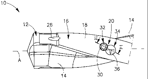
La présente invention concerne un outil de coupe rotatif (10) comportant une plaquette de coupe (34) montée sur l~outil de manière à coulisser. La plaquette de coupe (34) peut être déplacée d~une position rétractée à une position étendue au moyen d~un fluide sous pression qui agit directement sur la plaquette de coupe.


Abrégé anglais


A rotary cutting tool (10) having a cutting insert (34) slidably supported
therin. The cutting insert (34) is moveable from a retracted position to an
extended position by means of a pressurized fluid which bears directly against
the cutting insert.

Revendications

Note : Les revendications sont présentées dans la langue officielle dans laquelle elles ont été soumises.


CLAIMS:
1. A rotary cutting tool having a longitudinal axis of rotation and
comprising:
a conduit, for passage of fluid, formed in the cutting tool and extending
generally axially,
an insert pocket opening out to a peripheral surface of the cutting tool via
an aperture, the insert pocket communicating with the conduit,
a cutting insert slidably retained in the insert pocket, the cutting insert
being
slidable from a retracted position to an extended position by means of fluid
pressure applied by the fluid which bears against and biases the cutting
insert
towards the extended position, wherein in the extended position at least a
portion
of the cutting insert protrudes from the aperture beyond the peripheral
surface of
the cutting tool; and
a threaded holding member configured to prevent the cutting insert from
exiting the insert pocket and limit rotation of the cutting insert around an
insert
axis of the cutting insert.
2. The rotary cutting tool according to claim 1, wherein a holding bore opens
out to the peripheral surface and communicates with the insert pocket.
3. The rotary cutting tool according to claim 2, wherein the holding member is
located in the holding bore and abuts the cutting insert, when the cutting
insert is
in the extended position.
4. The rotary cutting tool according to claim 1, wherein the cutting insert
has
an insert axis defining a back to front direction and a plane including the
insert
axis passes therethrough, the cutting insert comprising:
a body portion having a back surface at a back end of the body portion, and
7

a cutting portion at a front end of the body portion, the cutting portion
having two cutting edges being reflection symmetric with respect to the plane.
5. The rotary cutting tool according to claim 4, wherein the pressurized fluid
bears directly against the back surface of the cutting insert.
6. The rotary cutting tool according to claim 1, wherein the rotary cutting
tool
is a drill.
7. A rotary cutting tool having a longitudinal axis of rotation and
comprising:
a conduit, for passage of fluid, formed in the cutting tool and extending
generally axially,
an insert pocket opening out to a peripheral surface of the cutting tool via
an aperture, the insert pocket communicating with the conduit,
a cutting insert slidably retained in the insert pocket, the cutting insert
being
slidable from a retracted position to an extended position in which at least a
portion of the cutting insert protrudes from the aperture beyond the
peripheral
surface of the cutting tool; and
a threaded holding member configured to prevent the cutting insert from
exiting the insert pocket and limit rotation of the cutting insert around an
insert
axis of the cutting insert; wherein:
a back surface of the cutting insert is in communication with the conduit
such that a fluid present in the conduit is capable of urging the cutting
insert from
the retracted position to the extended position, without the assistance of a
spring.
8. The rotary cutting tool according to claim 7, wherein a holding bore opens
out to the peripheral surface and communicates with the insert pocket.
8

9. The rotary cutting tool according to claim 8, wherein the holding member is
located in the holding bore and abuts the cutting insert when the cutting
insert is
in the extended position.
10. The rotary cutting tool according to claim 7, wherein the cutting insert
has
an insert axis defining a back to front direction and a plane including the
insert
axis passes therethrough, the cutting insert comprising:
a body portion having a back surface at a back end of the body portion, and
a cutting portion at a front end of the body portion, the cutting portion
having two cutting edges being reflection symmetric with respect to the plane.
11. The rotary cutting tool according to claim 7, wherein the rotary cutting
tool
is a drill.
9

Description

Note : Les descriptions sont présentées dans la langue officielle dans laquelle elles ont été soumises.


CA 02602761 2007-09-14
WO 2006/103650 PCT/IL2006/000340
ROTARY CUTTING TOOL
FIELD OF THE INVENTION
The present invention relates to a rotary cutting tool having a
cutting insert for deburring of bores.
BACKGROUND OF THE INVENTION
Such rotary cutting tools are known either in the fonn of stand
alone tools for deburring ready made holes or in the form of drills having
incorporated deburring capability. In both cases the deburring is generally
performed by a spring-loaded cutting insert. However, there are situations
in which there is not enough room for a spring. This can be the case for
very small diameter cutting tools or in drills where it is required to locate
the deburring insert in the vicinity of the drill's flutes.
US Patent 6,270,295 describes a cutting tool which utilizes
pressurized fluid for indirectly loading a blade. A piston 118 resides in a
side conduit 112 and pressurized fluid, flowing in the side conduit 112,
assists in pushing the piston 118 against a cartridge 122 which holds a blade
126.
It is an object of the present invention to provide an improved
deburring mechanism for a rotary cutting tool.
The objects of the invention are attained with the subject matter
in accordance with the respective claims.

CA 02602761 2007-09-14
WO 2006/103650 PCT/IL2006/000340
SUMMARY OF THE INVENTION
In accordance with the present invention there is preferably
provided a rotary cutting tool having a longitudinal axis of rotation and
comprising:
a conduit, for passage of fluid, formed in the cutting tool and
extending generally axially,
an insert pocket opening out to a peripheral surface of the cutting tool
via an aperture, the insert pocket communicating with the conduit, and
a cutting insert slidably retained in the insert pocket, the cutting insert
being slidable from a retracted position to an extended position by means of
fluid pressure applied by the fluid which bears against and biases the cutting
insert towards the extended position, wherein in the extended position at
least a portion of the cutting insert protrudes from the aperture beyond the
peripheral surface of the cutting tool.
Preferably, a holding bore opens out to the peripheral surface and
communicates with the insert pocket.
Typically, the cutting insert has an insert axis defining a back to
front direction and a plane including the insert axis passes there through,
the
cutting insert comprising:
a body portion having a back surface at a back end of the body portion,
and
a cutting portion at a fiont end of the body portion, the cutting portion
having two cutting edges being reflection symmetric with respect to the
plane.
Generally, the pressurized fluid bears directly against the back
surface of the cutting insert.
Preferably, a holding member is located in the holding bore and
abuts the cutting insert when the cutting insert is in the extended position.
2

CA 02602761 2007-09-14
WO 2006/103650 PCT/IL2006/000340
If desired, the rotary cutting tool is a drill.
The present invention provides the following preferred
advantages. No complex mechanisms or springs are required to bias the
deburring cutting insert. It enables the incorporation of the deburring insert
in a drill in the vicinity of the drill's flutes. The deburring insert can be
incorporated in small diameter tools in which there is insufficient room for
springs, or the like. Its implementation is simple and inexpensive. The
deburring insert may be loaded at the forward end of a drill, enabling the
drill to drill through holes and deburr both sides of the hole.
BRIEF DESCRIPTION OF THE DRAWINGS
For a better understanding of the present invention and to show
how the same may be carried out in practice, reference will now be made to
the accompanying drawings, in which:
Fig. 1 is a partial first side view of a drill having a deburring
mechanism in accordance with the present invention;
Fig. 2 is a partial second side view of the drill with its conduit and
deburring mechanism shown in hidden lines;
Fig. 3 is a cross sectional view of the deburring mechanism taken
along the line III-III in Fig 1;
Fig. 4 is similar to Fig. 3 but with a cutting insert and holding member
removed;
Fig. 5 is a perspective view the cutting insert in accordance with the
present invention; and
Fig. 6 is a top view of the cutting insert shown in Fig. 5.
DETAILED DESCRIPTION OF THE INVENTION
Attention is first drawn to Fig. 1. The present invention will be
described from herein with reference to a drill 10 however it will be clear to
3

CA 02602761 2007-09-14
WO 2006/103650 PCT/IL2006/000340
the skilled person in the art that it can be applicable to a variety of rotary
cutting tools where deburring is required. The drill 10 has a longitudinal
axis of rotation A defining a forward to rear direction and a cutting tip 12
located at a forward end thereof. Two flutes 14, extending rearwardly from
S the cutting tip 12 along a peripheral surface 16 of the drill 10, foml two
identical lands 18 therebetween. A deburring mechanism 20 in accordance
with the present invention is formed on one of the lands 18 adjacent the
cutting tip 12. It should be noted that directional terms appearing
throughout the specification and claims, e.g. "forward", "rear", "front",
"back", etc., are used as terms of convenience to distinguish various
surfaces relative to each other. Although these terms may be meaningful
with reference to particular component orientations, they are used for
illustrative purposes only, and are not intended to limit the scope of the
appended claims.
Attention is additionally drawn to Fig. 2. A conduit 22 for the passage
of fluid, having a main portion 24 and two minor portions 26, is formed in
the drill 10. The main portion 24 extends forwardly along the axis of
rotation A to a forward ending 28 adjacent the cutting tip 12. Each minor
portion 26 diverges forwardly and outwardly from the forward ending 28 to
a respective land 18. The deburring mechanism 20 includes a holding bore
30, a holding member 32 and a cutting insert 34 that is capable of lateral
movement between a retracted position and an extended position in a
generally cylindrical insert pocket 36. As will be described in greater detail
below, the cutting insert 34 is prevented fiom exiting the insert pocket 36 by
means of the holding member 32, and is loaded in the insert pocket 36 by
means of fluid pressure which bears directly against the cutting insert 34 at
one of its ends.
Attention is drawn to Figs. 4 to 6. The insert pocket 36 communicates
with the main portion 24 of the conduit 22 and opens out to the land 18 via
4

CA 02602761 2007-09-14
WO 2006/103650 PCT/IL2006/000340
an aperture 38. The holding bore 30 is formed in the land 18 adjacent the
insert pocket 36 and has a threaded portion 40 and a socket 42. The socket
42 extends outwardly from the threaded portion 40 and opens out to the land
18. The cutting insert 34 has an insert axis B defining a front to back
direction and comprises a generally cylindrical body portion 44 and a
cutting portion 46. The body portion 44 has a back surface 48 at a back end,
a front surface 50 at a front end and a peripheral body surface 52
therebetween. A plane P which includes the insert axis B divides the cutting
insert 34 into two sides. A holding recess 54 having a recess face 56 and a
back face 58 is fonned on the peripheral body surface 52, on one side of the
cutting insert 34, and opens out to the front surface 50. The recess face 56
has a concave arc shape in a cross section perpendicular to insert axis B and
the back face 58 is located at a back end of the holding recess 54 and is
perpendicular to the insert axis B. The cutting portion 46 has opposing
flank surfaces 60 and a top surface 62 which all extend foi-wardly from the
front surface 50 of the body portion 44 to an insert nose 64. The flank
surfaces 60 are located on opposing sides of the plane P. The top surface 62
bridges between the flank surfaces 60, is generally perpendicular to the
plane P and proximate to the insert axis B. The cutting portion 46 has two
cutting edges 66 located each between the top surface 62 and a respective
flank surface 60. The cutting edges 66 are reflection symmetric with
respect to the plane P and have each a rake surface 68 associated with the
top surface 62 and a relief surface 70 associated with the respective flank
surface 60.
Attention is additionally drawn to Fig. 3. The cutting insert 34 is
located in the insert pocket 36 with its back surface 48 facing inwardly. The
holding member 32 has a screw portion 72 and a head 74 which are,
respectively, threadingl.y received in the threaded portion 40 and located in
the socket 42 of the holding bore 30. The head 74 of the holding member
5

CA 02602761 2007-09-14
WO 2006/103650 PCT/IL2006/000340
32 protrudes into the insert pocket 36 and, when the cutting insert 34 is in
the extended position, abuts at least a portion of the back face 58 of the
holding recess 54. Rotation of the cutting insert 34 in a given direction
around the insert axis B is limited in the insert pocket 36 by the head 74 of
the holding member 32 abutting against the recess face 56 of the holding
recess 54. Loading of the cutting insert 34 in the insert pocket 36 is
provided by fluid that flows through the conduit 22 and into the insert
pocket 36. The fluid pressure that is formed in the insert pocket 36 bears
against the back surface 48 of the cutting insert 34 forming a force which
biases and urges the cutting insert 34 radially outwardly.
Although the present invention has been described to a certain degree
of particularity, it should be understood that various alterations and
modifications could be made without departing from the scope of the
invention as hereinafter claimed.
6

Dessin représentatif
Une figure unique qui représente un dessin illustrant l'invention.
États administratifs

2024-08-01 : Dans le cadre de la transition vers les Brevets de nouvelle génération (BNG), la base de données sur les brevets canadiens (BDBC) contient désormais un Historique d'événement plus détaillé, qui reproduit le Journal des événements de notre nouvelle solution interne.

Veuillez noter que les événements débutant par « Inactive : » se réfèrent à des événements qui ne sont plus utilisés dans notre nouvelle solution interne.

Pour une meilleure compréhension de l'état de la demande ou brevet qui figure sur cette page, la rubrique Mise en garde , et les descriptions de Brevet , Historique d'événement , Taxes périodiques et Historique des paiements devraient être consultées.

Historique d'événement

Description Date
Inactive : Demande ad hoc documentée 2016-11-28
Demande visant la révocation de la nomination d'un agent 2016-11-03
Demande visant la nomination d'un agent 2016-11-03
Le délai pour l'annulation est expiré 2015-03-16
Lettre envoyée 2014-03-17
Requête visant le maintien en état reçue 2013-02-26
Accordé par délivrance 2011-02-15
Inactive : Page couverture publiée 2011-02-14
Préoctroi 2010-12-03
Inactive : Taxe finale reçue 2010-12-03
Un avis d'acceptation est envoyé 2010-11-19
Lettre envoyée 2010-11-19
Un avis d'acceptation est envoyé 2010-11-19
Inactive : Approuvée aux fins d'acceptation (AFA) 2010-11-15
Modification reçue - modification volontaire 2010-10-19
Inactive : Dem. de l'examinateur par.30(2) Règles 2010-05-04
Lettre envoyée 2009-02-16
Exigences pour une requête d'examen - jugée conforme 2009-01-16
Toutes les exigences pour l'examen - jugée conforme 2009-01-16
Requête d'examen reçue 2009-01-16
Lettre envoyée 2008-09-03
Inactive : Transfert individuel 2008-06-03
Inactive : Page couverture publiée 2007-12-04
Inactive : Décl. droits/transfert dem. - Formalités 2007-12-04
Inactive : Notice - Entrée phase nat. - Pas de RE 2007-11-30
Inactive : CIB en 1re position 2007-10-27
Demande reçue - PCT 2007-10-26
Exigences pour l'entrée dans la phase nationale - jugée conforme 2007-09-14
Demande publiée (accessible au public) 2006-10-05

Historique d'abandonnement

Il n'y a pas d'historique d'abandonnement

Taxes périodiques

Le dernier paiement a été reçu le 2011-02-09

Avis : Si le paiement en totalité n'a pas été reçu au plus tard à la date indiquée, une taxe supplémentaire peut être imposée, soit une des taxes suivantes :

  • taxe de rétablissement ;
  • taxe pour paiement en souffrance ; ou
  • taxe additionnelle pour le renversement d'une péremption réputée.

Les taxes sur les brevets sont ajustées au 1er janvier de chaque année. Les montants ci-dessus sont les montants actuels s'ils sont reçus au plus tard le 31 décembre de l'année en cours.
Veuillez vous référer à la page web des taxes sur les brevets de l'OPIC pour voir tous les montants actuels des taxes.

Historique des taxes

Type de taxes Anniversaire Échéance Date payée
Taxe nationale de base - générale 2007-09-14
TM (demande, 2e anniv.) - générale 02 2008-03-17 2008-02-12
Enregistrement d'un document 2008-06-03
Requête d'examen - générale 2009-01-16
TM (demande, 3e anniv.) - générale 03 2009-03-16 2009-02-09
TM (demande, 4e anniv.) - générale 04 2010-03-15 2010-02-09
Taxe finale - générale 2010-12-03
TM (demande, 5e anniv.) - générale 05 2011-03-15 2011-02-09
TM (brevet, 6e anniv.) - générale 2012-03-15 2012-01-04
TM (brevet, 7e anniv.) - générale 2013-03-15 2013-02-26
Titulaires au dossier

Les titulaires actuels et antérieures au dossier sont affichés en ordre alphabétique.

Titulaires actuels au dossier
ISCAR LTD.
Titulaires antérieures au dossier
DMITRI TCHORNY
DOV YOFFE
Les propriétaires antérieurs qui ne figurent pas dans la liste des « Propriétaires au dossier » apparaîtront dans d'autres documents au dossier.
Documents

Pour visionner les fichiers sélectionnés, entrer le code reCAPTCHA :


Pour visualiser une image, cliquer sur un lien dans la colonne description du document. Pour télécharger l'image (les images), cliquer l'une ou plusieurs cases à cocher dans la première colonne et ensuite cliquer sur le bouton "Télécharger sélection en format PDF (archive Zip)" ou le bouton "Télécharger sélection (en un fichier PDF fusionné)".

Liste des documents de brevet publiés et non publiés sur la BDBC .

Si vous avez des difficultés à accéder au contenu, veuillez communiquer avec le Centre de services à la clientèle au 1-866-997-1936, ou envoyer un courriel au Centre de service à la clientèle de l'OPIC.


Description du
Document 
Date
(aaaa-mm-jj) 
Nombre de pages   Taille de l'image (Ko) 
Description 2007-09-13 6 264
Dessin représentatif 2007-09-13 1 7
Dessins 2007-09-13 3 53
Revendications 2007-09-13 2 57
Abrégé 2007-09-13 1 55
Revendications 2010-10-18 3 104
Dessin représentatif 2011-01-26 1 8
Rappel de taxe de maintien due 2007-12-02 1 112
Avis d'entree dans la phase nationale 2007-11-29 1 194
Courtoisie - Certificat d'enregistrement (document(s) connexe(s)) 2008-09-02 1 103
Accusé de réception de la requête d'examen 2009-02-15 1 176
Avis du commissaire - Demande jugée acceptable 2010-11-18 1 163
Avis concernant la taxe de maintien 2014-04-27 1 170
PCT 2007-09-13 5 159
Correspondance 2007-11-29 1 25
Correspondance 2010-12-02 1 33
Taxes 2012-01-03 1 24
Taxes 2013-02-25 1 24
Correspondance 2016-11-02 3 133