Note : Les descriptions sont présentées dans la langue officielle dans laquelle elles ont été soumises.
CA 02603072 2010-04-06
28964-142
1
DESCRIPTION
OPTICAL SCANNING ACTUATOR
TECHNICAL FIELD
[0001] The present invention relates to an optical
scanning actuator.
BACKGROUND ART
[0002] Scanning laser radar devices, laser scanners,
laser printers, laser markers, and object surveillance
devices, for example, are known examples of devices that use
a laser scanning device. Among these devices, the scanning
laser radar device, which is deployed for prevention of
vehicle collision, uses a scanning device having a leaf-
spring type optical scanning actuator. In the leaf-spring
type optical scanning actuator, an optical element such as a
reflective mirror is fitted to a leaf spring member. The
base of the leaf spring member is fixed and the tip is
oscillated by an electromagnetic driving unit. A light beam
from a light source fitted at a predetermined spot distinct
from the spot where the leaf spring member is disposed, is
20. scanned by the optical element by reflecting or refracting
the light beam (see Patent document 1). Compared to a
motor-type optical scanning actuator in which the light beam
is oscillated by rotating the reflective mirror using a
motor, the leaf-spring type optical scanning actuator has a
simpler structure and is smaller, more rugged, and
economical.
[0003] [Patent document 1] International Publication No.
02/008818 pamphlet
CA 02603072 2010-04-06
28964-142
2
DISCLOSURE OF INVENTION
[0004] An optical scanning actuator disclosed in Patent
document 1 is described below with reference to Fig. 14. A
reflective mirror 3 is fitted to the tip end of a leaf
spring member 2 whose base end is fitted on a fixed member
1. A light beam outgoing from a light source 4 fitted at a
predetermined spot which is distinct from the fixed member 1
is reflected as a light beam Ll by the reflective mirror 3
at a neutral position Pl. The extent to which the optical
scanning actuator having such a structure can scan is
limited to an angle (=scanning angle) formed between the
light beam Ll and a light beam L2, which is the light beam
outgoing from the light source 4 reflected by the reflective
mirror 3 at a swung position P2.
[0005] To enable the actuator disclosed in Patent
document 1 to scan light across a significantly wide angle
like a low-speed follow-up device of a vehicle, the light
beam outgoing from the light source 4 must be received and
reflected within the range of oscillation of the leaf spring
member 2. To achieve this, the actuator needs to be
provided with a reflective mirror 5 larger than the
reflective mirror 3, as shown in Fig. 15. Thus, a larger
angle (scanning angle) 02 (which is >01) is formed between
the light beam reflected as the light beam L1 by the
reflective mirror 5 at the neutral position P1 and the light
beam reflected as L3 by the reflective mirror 5 at a swung
position P3. However, this would mean that the leaf spring
member 2 has to support a heavy and large reflective mirror
5, hindering stabilized oscillation of the leaf spring
member 2 and making it difficult to sustain high-speed
scanning, thus adversely affecting scanning performance such
as responsiveness.
CA 02603072 2010-04-06
28964-142
3
[0006] It is an object of some embodiments of the present
invention to provide an optical scanning actuator that
achieves a wide scanning angle with a simple structure while
-preserving all the advantages of a leaf-spring type optical
scanning actuator.
[0007] According to the present invention, there is
provided an optical scanning actuator comprising: a leaf
spring member that has a base end fixed and a tip end; a
light source that is fitted to the leaf spring member; an
.10 electromagnetic driving unit that oscillates the tip end of
the leaf spring member; and an optical element that is
fitted to the leaf spring member and that is irradiated with
light outgoing from the light source to reflect or refract
the light to thereby scan the light.
'15 [0008] In some embodiments, the optical element may be
fitted to the tip end of the leaf spring member orthogonal
to an outgoing direction of the light beam outgoing from the
light source and may be a lens that refracts the light beam
outgoing from the light source.
20= [0009] In some embodiments, the optical element may be
fitted to the tip end of the leaf spring member inclined at
an angle relative to an outgoing direction of the light beam
outgoing from the light source and may be a reflective
mirror that reflects the light beam outgoing from the light
-25 source.
[0010] In some embodiments, the light source may be
fitted to a base end of a slit running from the tip end of
the leaf spring member to the base end of the leaf spring
member.
CA 02603072 2010-04-06
28964-142
4
[0011] In some embodiments, the light source may be
fitted to one of the edges in a width direction on the leaf
spring member.
[0012] In some embodiments, the light source may be
fitted on a side of the leaf spring member.
[0013] In some embodiments, the leaf spring member may
include a plurality of leaf springs joined by a joint, and
the light source may be fitted to the joint.
[0014] In some embodiments, the optical scanning actuator
may be deployed in an on-board laser scanning mechanism for
- detecting obstacles such as vehicle ahead and pedestrians.
[0015] In some embodiments, the optical scanning actuator
may be deployed in a laser scanning mechanism as a part of
an infrastructure detecting obstacles such as vehicle ahead
and pedestrians.
[0016] In some embodiments, the optical scanning actuator
may be deployed in a crime-prevention or care-providing
laser radar scanning mechanism for detecting conditions
prevailing indoors such as any change in the conditions and
human activity.
[0017] In the optical scanning actuator according to
embodiments of the present invention, a light source is
fitted to a.leaf spring member, enabling the light source to
follow the movement of an optical element, which oscillates
with the leaf spring member, obviating the need for a large
optical element, and preventing a resulting deterioration of
scanning performance. Thus, an optical scanning actuator
CA 02603072 2007-09-28
that achieves a wide scanning angle with a simple structure
while preserving all the advantages of a leaf-spring type
optical scanning actuator is realized.
BRIEF DESCRIPTION OF DRAWINGS
5 [0018] [Fig. 1] Fig. 1 is a perspective view of an
optical scanning actuator according to a first embodiment
of the present invention.
[Fig. 2] Fig. 2 is a schematic for explaining a principle
of the optical scanning actuator shown in Fig. 1 for
scanning a light beam.
[Fig. 3] Fig. 3 is a schematic for explaining a principle
of a conventional optical scanning actuator for scanning a
light beam.
[Fig. 4] Fig. 4 is a schematic for explaining a principle
used in the optical scanning actuator shown in Fig. 3 for
scanning a light beam, wherein the optical scanning
actuator includes a large lens to increase a scanning angle.
[Fig. 5] Fig. 5 is a perspective view of a first
modification of the optical scanning actuator according to
the first embodiment.
[Fig. 6] Fig. 6 is a perspective view of a second
modification of the optical scanning actuator according to
the first embodiment
[Fig. 7] Fig. 7 is a perspective view of a third
modification of the optical scanning actuator according to
the first embodiment.
[Fig. 8] Fig. 8 is a perspective view of an optical
scanning actuator according to a second embodiment of the
present invention.
[Fig. 9] Fig. 9 is a schematic for explaining a principle
of the optical scanning actuator shown in Fig. 8 for
scanning a light beam.
[Fig. 10] Fig. 10 is a perspective view of a first
CA 02603072 2010-04-06
28964-142
6
modification of the optical scanning actuator according to
the second embodiment.
[Fig. 11] Fig. 11 is a perspective view of a second
modification of the optical scanning actuator according to
the second embodiment.
[Fig. 12] Fig. 12 is a perspective view of a first
modification of a leaf spring used in the optical scanning
actuator according to an embodiment of the present
invention.
[Fig. 13] Fig. 13 is a perspective view of a second
modification of the leaf spring used in the optical scanning
actuator according to an embodiment of the present
invention.
[Fig. 14] Fig. 14 is a schematic diagram of the
.15 conventional optical scanning actuator and a schematic for
explaining a principle of the conventional optical scanning
actuator for scanning a light beam.
[Fig. 15] Fig. 15 is a schematic for explaining how an
operating angle can be widened by using a larger reflective
20, mirror in the actuator shown in Fig. 14.
EXPLANATIONS OF LETTERS OR NUMERALS
[0019] 10 Actuator
11 Base
12 Supporting member
25 13 Leaf spring member
13a Base-end frame
13b Tip-end frame
13c Leaf spring
13d Slit
30 13e Joint
CA 02603072 2010-04-06
28964-142
6a
13f Flange
13g Bracket
14 Coil
15 Permanent magnet
16 Yoke
CA 02603072 2007-09-28
7
17 Bracket
18 Light source
19 Lens
20 Actuator
21 Reflective mirror
BEST MODE(S) FOR CARRYING OUT THE INVENTION
[First embodiment]
[0020] An optical scanning actuator according to a first
embodiment of the present invention is described below with
reference to the accompanying drawings. Fig. 1 is a
perspective view of an optical scanning actuator according
to the first embodiment of the present invention. Fig. 2
is a schematic for explaining the principle of the optical
scanning actuator shown in Fig. 1 for scanning a light beam.
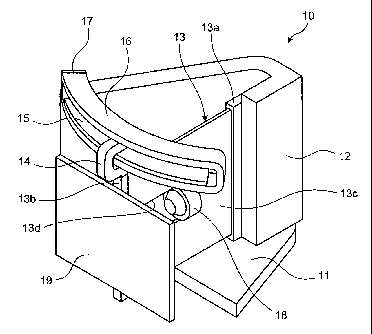
[0021] As shown in Fig. 1, an optical scanning actuator
(hereinafter, "actuator") 10 includes a leaf spring member
13, a coil 14, a light source 18, and a lens 19.
[0022] As shown in Fig. 1, the leaf spring member 13
includes a base-end frame 13a and a tip-end frame 13b,
supporting therebetween a leaf spring 13c. The base-end
frame 13a is fixed to a supporting member 12 fitted to a
base 11. A slit 13d runs from the tip end towards the base
end of the leaf spring 13c. The light source 18 is fitted
at the base end of the slit 13d. The leaf spring 13c is a
thin leaf made of a springy material such as beryllium
copper, phosphor bronze, or stainless steel, and is
flexible orthogonal to the leaf surface. A flexible
printed board with conductor patterns formed thereon is
bonded to the leaf spring 13c. The flexible printed board
supplies electric power to the light source 18 and the coil
14. If the leaf spring 13c is made of copper, the leaf
spring 13c can be divided into a ground portion and an
electric power receiving portion with an insulator
CA 02603072 2007-09-28
8
therebetween, and the leaf spring 13c itself can be used
for supplying electric power.
[0023] The coil 14 is disposed above the tip-end frame
13b, and forms an electromagnetic driving unit along with a
permanent magnet 15 set in a yoke 16 as shown in Fig. 1.
The permanent magnet 15 is set along the arc of the yoke 16
in the lower portion within the yoke 16. The yoke 16 is a
planar arc shaped soft magnetic member made of pure iron,
for example, and has the coil 14 around it. One end of the
yoke 16 is supported by a bracket 17 on the upper edge of
the supporting member 12. Depending on the direction of
the current flowing through the coil 14, the Lorentz force
is generated towards the left or the right along the arc of
the yoke, which is disposed transverse to a flux produced
between the permanent magnet 15 and the yoke 16. The coil
14 moves due to the Lorentz force, causing the leaf spring
member 13 to oscillate. The oscillation range of the leaf
spring member 13 will be the range in which the Lorentz
force and the opposing bending force counterbalance each
other. An alternating current of 10 to 100 Hz flows
through the coil 14.
[0024] A light-emitting element such as a laser diode
(LD) or a light-emitting diode (LED) that emits spot-type
parallel light beams is used as the light source 18. As
shown in Fig. 1, the light source 18 is fitted at the base
end of the slit 13d in the leaf spring 13c. The light
source 18 follows the movement of the lens 19, which
oscillates with the leaf spring member 13. The magnitude
of movement of the light source 18 is proportional to the
magnitude of movement of the lens 19, and can be set to any
value according to the shape of the leaf spring 13c or
where the light source is fitted to the leaf spring 13c.
[0025] As shown in Fig. 1, the lens 19 is fitted to the
CA 02603072 2007-09-28
9
tip-end frame 13b of the leaf spring member 13, and
refracts the light beam outgoing from the light source 18.
The lens 19 is disposed orthogonal to the outgoing
direction of the light beam from the light source 18.
However, the lens 19 can be disposed at any angle relative
to the outgoing direction of the light beam as long as wide
angle scanning of the light beam is enabled. A light
Fresnel lens is used as the lens 19 so as not to obstruct
the oscillation of the leaf spring member 13.
[0026] When scanning the light beam outgoing from the
light source 18, the current flowing through the coil 14 of
the actuator 10 causes the leaf spring member 13 to
oscillate. As the light source 18 is fitted to the leaf
spring 13c, that is, to the base end of the slit 13d of the
leaf spring member 13, when the leaf spring member 13
starts to oscillate from a neutral position Pl, a light
beam L1 outgoing from the light source 18 at the neutral
position Pl passes through the lens 19, also at the neutral
position Pl and, as shown in Fig. 2, propagates straight
ahead. As the light source 18 also shifts when the
oscillating leaf spring member 13 shifts to a swung
position, an optical axis of the outgoing light beam never
fails to fall on the lens 19.
[0027] However, as shown in Fig. 2, the magnitude to
which the leaf spring 13c bends at the spot where the light
source 18 is fitted is small, a light beam L2 outgoing from
the light source 18 becomes incident on the outer periphery
of the lens 19, which has now shifted to a swung position
P2, is diffracted by a huge angle, and comes out of the
lens 19 as a light beam L3. Thus, fitting the light source
18 to the oscillating leaf spring member 13 enables the
actuator 10 to scan the light beam outgoing from the light
source 18 by up to a scanning angle of 010.
CA 02603072 2007-09-28
28964-142
[0028] In the conventional actuator in which the light
source is fixed to a supporting member, and in which a
lens 7 similar to the lens 19 is fitted to the tip end of
the leaf spring member 2, as shown in Fig. 3, when the leaf
5 spring member 2 is not oscillating, the light beam outgoing
from the light source 4 passes through the lens 7 at the
neutral position P1, and propagates straight ahead as the
light beam Ll. When the leaf spring member 2 starts
oscillating, and as a result, the lens 7 shifts to the swung
10 position P2, as shown in Fig. 3, the light beam becomes
incident on the outer periphery of the lens 7, and comes out
of the lens 7 as a refracted light beam L4, yielding a
smaller scanning angle of 03 (which is less than 910) due to
restricted oscillation range of the lens 7.
[0029] If a lens 9 that is larger than the lens 7 is used
in the conventional actuator as shown in Fig. 4, and the
leaf spring member 2 is made to oscillate with a greater
amplitude than that shown in Fig. 3, a scanning angle of 04
(which is equal to 010), which is larger than the scanning
angle of 03 can be obtained. However, the scanning
performance such as responsiveness will be adversely
affected due to increased size and the weight.
[0030] Thus, in the actuator 10 according to the present
invention in which the light source 18 is fitted to the leaf
spring member 13, the light beam from the light source 18
follows the movement of the lens 19 which oscillates with
the leaf spring member 13, thereby causing the optical axis
of the outgoing light beam to never fail to fall on the lens
19. As a result, with a simple structural modification, a
wider scanning angle of the light outgoing from the light
source 18 than that of a conventional actuator can be
achieved while preserving all the
CA 02603072 2007-09-28
11
advantages of a leaf-spring type optical scanning actuator.
[0031] In one variation of the actuator 10, as shown in
Fig. 5, a plurality of leaf springs 13c can be provided
with a joint 13e joining the leaf springs 13c, and the
light source 18 can be fitted to the joint 13e. The coil
14, the permanent magnet 15, and the yoke 16 are not shown
in the actuator shown in Fig. 5 as well as in Figs. 6, 7,
10, 11, and 12 that will be referred to in the following
description.
[0032] In another variation of the actuator 10, as shown
in Fig. 6, the light source 18 can be fitted to a flange
13f provided on one of the top edges in a width direction
on the leaf spring 13c. In yet another variation, as shown
in Fig. 7, the light source 18 can be fitted to a bracket
13g provided on a side of the leaf spring 13c. In these
modifications of the actuator 10, the magnitude of shift of
the light source 18 with the oscillation of the leaf spring
member 13 can be set by changing the position of the flange
13f and the bracket 13g in the length direction of the leaf
spring 13c.
[Second embodiment]
[0033] A second embodiment of the actuator according to
the present invention is described below with reference to
the accompanying drawings. The optical element fitted to
the leaf spring member in the actuator according to the
first embodiment is a lens, whereas a reflective mirror is
used as the optical element in the actuator according to
the second embodiment. Fig. 8 is a perspective view of the
optical scanning actuator according to the second
embodiment. Fig. 9 is a schematic for explaining the
principle of the optical scanning actuator shown in Fig. 8
for scanning the light beam. The parts of the optical
scanning actuator in Figs. 8 and 9 that are identical to
CA 02603072 2007-09-28
12
those of the actuator 10 according to the first embodiment
have been assigned the same reference numerals.
[0034] In an actuator 20, a reflective mirror 21 that
refracts the light beam outgoing from the light source 18
is fitted to the tip-end frame 13b of the leaf spring
member 13. The reflective mirror 21 is fitted to the tip-
end of the leaf spring member 13 inclined at 45 relative
to the outgoing direction of the light beam outgoing from
the light source 18. The reflective mirror 21 can be
fitted at any angle as long as it can reflect the light
beam outgoing from the light source 18 enabling wide-angle
scanning.
[0035] Thus, when scanning the light beam outgoing from
the light source 18, the current flowing through the coil
14 of the actuator 20 causes the leaf spring member 13 to
oscillate. As the light source 18 is fitted at the base
end of the slit 13d of the leaf spring 13c, when the leaf
spring member 13 starts to oscillate from the neutral
position P1, the light beam L1 outgoing from the light
source 18 at the neutral position P1 is reflected by the
reflecting mirror 21 and, as shown in Fig. 9, its
propagation direction is deflected by 90 . As shown in Fig.
9, when the leaf spring member 13 starts oscillating and as
a result the light source 18 shifts to the swung position
P2, the magnitude to which the leaf spring 13c bends at the
spot P2 where the light source 18 is fitted is small.
Therefore, as shown in Fig. 9, the light beam L2 outgoing
from the light source 18 at the swung position P2 is
reflected as a light beam L3 by the outer periphery of the
reflective mirror 21 that has shifted to the swung position
P2.
[0036] Thus, fitting the light source 18 to the
oscillating leaf spring member 13 enables the actuator 20
CA 02603072 2007-09-28
13
to scan the light beam outgoing from the light source 18 by
up to a scanning angle of 011. The scanning angle 011 is
equal to the scanning angle 02 of the conventional actuator
shown in Fig. 15 that uses the large reflective mirror 5
(011=02). Thus, in the actuator 20, a wide scanning angle
is achieved without having to use the large reflective
mirror 5 by fitting the light source 18 to the leaf spring
member 13, enabling the light source 18 to shift with the
left spring member 13.
[0037] In one variation of the actuator 20, as shown in
Fig. 10, the light source 18 can be fitted to the flange
13f provided on one of the top edges in a width direction
on the leaf spring 13c. In another variation, as shown in
Fig. 11, the light source 18 can be fitted to the bracket
13g provided on a side of the leaf spring 13c. In these
modifications of the actuator 20, the magnitude of shift of
the light source 18 with the oscillation of the leaf spring
member 13 can be set by changing the position of the flange
13f and the bracket 13g in the length direction of the leaf
spring 13c. In yet another variation of the actuator 20,
similarly to the actuator 10 shown in Fig. 5, the light
source 18 can be fitted to the joint 13e between the leaf
springs 13c.
[0038] Other modifications can also be made in the
actuators according to the first and second embodiments.
For example, as shown in Fig. 12, in the actuator 10
according to the first embodiment, a significant portion of
the tip end of the leaf spring 13c can be ablated, causing
the section modulus to drop towards the tip end of the leaf
spring 13c leading to a significant bend on the tip end
side. A drop in the section modulus towards the tip end of
the leaf spring 13c leading to a significant bend on the
CA 02603072 2007-09-28
28964-142
14
tip end side can also be achieved by modifying the leaf
spring 13c so that its thickness decreases gradually from
the base-end frame 13a towards the tip-end frame 13b, as
shown in Fig. 13.
[0039] The optical element used in the actuators
according to the first and the second embodiments are lens
and reflective mirror, respectively. However, other optical
elements such as a hologram element and a prism can be used.
[0040] The optical scanning actuator according to the
present invention can be deployed in an on-board laser radar
scanning mechanism for detecting obstacles such as vehicle
ahead and pedestrian, or in a laser radar scanning mechanism
which is part of an infrastructure for detecting obstacles
such as vehicle ahead and pedestrian, or in a crime-
prevention or care-providing laser radar scanning mechanism
for detecting conditions prevailing indoors such as any
change in the conditions and human activity.
Industrial Applicability
[0041] Thus, the optical scanning actuator according to
the present invention is useful as a leaf-spring type
optical scanning actuator that scans the light beam outgoing
from a light source by reflecting or refracting the light
beam, and is particularly useful as an optical scanning
actuator with a wide scanning angle.