Note : Les descriptions sont présentées dans la langue officielle dans laquelle elles ont été soumises.
CA 02603134 2007-10-01
1
Cable bushing device
Description
The invention relates to a cable bushing device for passing electrical cables
through, in
particular, two adjacent housings which are explosion and / or flame-proof. A
cable
bushing device of this nature comprises a sleeve-like external body which can
be
inserted by the opposite first and second end sections into corresponding
housing
bores. Furthermore, a device of this nature comprises at least one insert for
insertion
into an axial opening of the external body for holding the electrical cables
which are
passed through the cable bushing device. A fixing device is used here to mount
the
cable bushing device on at least one of the housings.
Cable bushing devices of this nature are for example known from DE 3 732 576
and DE
3 710 276. Through these said devices two housings are electrically connected
together
through housing walls which face one another in that the corresponding
electrical cables
are passed through the walls and the housing bores formed in them by means of
the
cable bushing device, also generally in an explosion and / or flame-proof
manner. A
device of this nature comprises an essentially sleeve-like external body,
which is
inserted through the housing bores and which terminates in the housings to be
joined
together electrically. In this external body one or also more inserts are
arranged through
which the corresponding electrical cables are passed and optionally held or
fixed. In
order to fix in particular the external body with regard to the housing bores
or the
housing walls, the external body generally comprises two external threads as
fixing
device, with which it is screwed to corresponding internal threads in each of
the housing
bores.
Through the use of a fixing device of this nature with two external and two
corresponding internal threads the appropriate explosion and / or flame-proof
protection
results, wherein optionally additional sealing elements or similar features
are provided.
However, the alignment of the housing bores must be very accurate so that a
screwed
joint of this nature is possible without faults. Similarly, extremely narrow
tolerances
CA 02603134 2012-07-19
77525-10
2
apply to the corresponding threads, so that not only the alignment of the
housing
bores takes place correctly with respect to the external body, but rather also
a
trouble-free screwing action is possible.
Furthermore, with the prior state of the art it should be noted that with
an external body already screwed into a housing bore and appropriately fixed
for
mounting in the other housing bore, essentially the complete second housing
must be
rotated to form the screw joint with the external body. This requires a
relatively large
amount of space for rotating the housing itself and is sometimes possible only
with
restrictions or not possible at all. In addition, when rotating the housing
itself the
corresponding assignment of the internal thread of the housing bore and the
external
thread of the external body is extremely difficult due in part to the lack of
alignment of
the housing bore and the external body.
Some embodiments disclosed herein relate to a cable bushing device of
the type mentioned in the introduction such that the assembly is simplified
with the
retention of all positive properties with regard to explosion and/or flame-
proof
protection and also wider tolerances are possible during the production of the
housing bores.
Some embodiments disclosed herein relate to cable bushing device for
the passage of electrical cables through in particular two adjacent, explosion
and/or
flame-proof housings, said cable bushing device comprising: a sleeve-like
external
body, which with oppositely situated first and second end sections can be
inserted
into corresponding bores in the housings; at least one insert inserted into an
axial
opening of the external body for retaining the electrical cables which are
passed
through the device; and a fixing device for fastening the device at least to
one
housing, wherein the fixing device on the first end section has an external
thread
formed to match an internal thread of the corresponding housing bore, a
mounting
nut which can be screwed onto the first end section and a limit-stop element
assigned
to the second end section and which essentially protrudes radially outwards,
wherein
CA 02603134 2012-07-19
77525-10
2a
the external body has at least in some places a spacing element which
protrudes
radially outwards approximately in the middle and which is arranged between
the
housings when the cable bushing device is in place.
According to the invention only one of the housing bores has an
appropriate internal thread into which the external body with the
corresponding
external thread is screwed. When the cable bushing device is mounted to one
housing, the other housing bore can be simply pushed onto the other end
section of
the external body which has not yet been fixed, because at this point no
screwing
action takes place between the housing bore and the external body. Thus wider
tolerances are possible for this corresponding housing bore.
In this connection, to ensure that the external body is fixed also relative
to this housing without an internal thread being formed in its housing bore, a
limit-stop
element protruding radially outwards is assigned to the corresponding end
section of
the external
CA 02603134 2007-10-01
3
,
body. The said limit-stop element presses from the inner side of the housing
onto the
corresponding housing wall and fixes it with respect to the housing screwed to
the
external body. To make the contact pressure between the limit-stop element and
the
housing wall sufficiently large, a mounting nut, which can be brought into
contact
against the corresponding inner side of the assigned housing wall, is arranged
on the
end section of the external body which is screwed to the other housing,
wherein due to
the nut being screwed onto the first end section, the limit-stop element
presses with
sufficient contact force onto the inner wall of the other housing. Thus on one
hand the
cable bushing device is correctly positioned between both housings and on the
other
hand fixing of the corresponding housings relative to one another occurs
simultaneously.
Due to these measures according to the invention, the assembly of the cable
bushing
device is substantially simplified and can be carried out more quickly. At the
same time
wider tolerances are possible at least with the housing bore which is not to
be screwed,
because it is simply pushed onto the second end section of the external body.
The limit-stop element can be placed on the second end section of the external
body in
various ways after insertion into the corresponding housing bore and fixed to
this
second end section.
In order to maintain in a simple manner a certain spacing between the housings
after
insertion of the cable bushing device, the external body can have a spacing
element
approximately centrally which protrudes at least in some places radially
outwards and
which is arranged between the housings with the cable bushing device in place.
This
spacing element can be formed elastic and compressible to facilitate an
adequate
contact force of the limit-stop element when the mounting nut is screwed on.
In a simple embodiment the spacing element can be formed as a circumferential
edge
flange around the external body. This flange can be formed in one piece with
the
external body. The materials for the edge flange and the rest of the external
body can
be different.
CA 02603134 2007-10-01
4
,
The corresponding end sections of the external body are formed in a circular
shape for
insertion, wherein the remaining external body outside of these end sections
can also
have other geometrical shapes. However, to simplify the manufacture of the
external
body, it can have an essentially circular shaped cross-section and the edge
flange can
run circumferentially around it in an annular shape.
In order to ensure that the corresponding explosion and / or flame-proof
protection can
be maintained between the housings in a simple manner, the edge flange can
have, in
particular on both its side faces facing the housings, a circumferential
sealing element.
A sealing element of this nature can be for example an 0-ring. Furthermore,
the side
faces can be formed as gap surfaces, wherein the explosion and / or flame-
proof
protection is in particular ensured.
In order to simplify the fitting of the external body in this connection, the
sealing element
can be partially arranged in a retaining recess formed in the side face. Thus,
the sealing
element is held during assembly and release of the sealing element during
assembly or
also during transport of the cable bushing device is essentially prevented.
In order to be able to also optionally arrange different inserts in the
external body, an
insert of this nature can be inserted detachably within the axial opening.
Different inserts
can be used for example for passing through different numbers of electrical
cables, for
holding electrical cables of different diameters or similar uses.
There is also the possibility of arranging a number of inserts one behind the
other in the
axial direction of the axial opening, refer for example to DE 3 732 576, and
of arranging
further spacing bodies between the inserts.
There is also the possibility that only one insert is used, which has at least
one
receptacle running essentially in the axial direction, which accommodates the
electrical
cables and optionally also holds them. An appropriate receptacle of this
nature can
comprise a row of channels through each of which an electrical cable is
passed. A
CA 02603134 2007-10-01
receptacle of this nature can also have one or more insertion openings for
plugging in
plug connection devices fitted to the electrical cables. In this way
essentially no direct
passage of an electrical cable occurs through the cable bushing device, but
rather the
passage occurs via a plug connection device with appropriately mutually
matching plug
connectors on each of the electrical cables to be connected.
With one example of this type of plug connection device with flat plugs and
flat
receptacles the plug opening can be formed essentially slot shaped for the
insertion of a
flat plug of this nature. This type of flat plug is arranged at one end of an
electrical cable
which is introduced into the cable bushing device from a housing. From the
other
housing another electrical cable with a corresponding flat receptacle is
introduced into
the cable bushing device and then connected with a flat plug held in the plug
opening.
With a simple embodiment of the above mentioned limit stop the said limit stop
can be
arranged on the second end section and in particular as a screw-on limit-stop
nut. After
the arrangement of the external body between both housings and insertion of
the
corresponding end sections into the assigned housing bores, this nut is fitted
to the
second end section where it is screwed on. Thus, there is the possibility of
screwing on
appropriate nuts practically from both ends of the external body and of
pressing the
assigned housing walls onto the sealing elements of the spacing element or
edge
flange.
To optionally prevent damage to the housing wall on screwing on the
corresponding
nuts or also to facilitate fastening relative to the housing wall with
relative few
revolutions of the corresponding nuts, an essentially annular spacing part can
be
arranged between the limit-stop nut and / or between the mounting nut and edge
flange.
With the external body inserted into the corresponding housing bores, this
part contacts
in each case the housing wall opposite the edge flange and facilitates an
adequate
fastening through a few revolutions of the corresponding nut.
The effect of this spacing part can also be thus improved if it is formed as a
spring
washer.
CA 02603134 2007-10-01
6
The insertion in particular of the second end section into the housing bore
without an
internal thread can thus be further simplified if the external body has on at
least this end
section at least two in particular opposite flat regions on its outer side.
In the following the invention will be explained based on the drawings
included in the
figures.
The following are shown:
Figure 1 a longitudinal section through two adjacently arranged housings
provided
with a cable bushing device according to the invention;
Figure 2 an enlarged illustration of the detail "X" of Figure 1;
Figure 3 a longitudinal section through the cable bushing device according
to Figure
2; and
Figure 4 a perspective diagonal view from one side of two adjacently
arranged cable
bushing devices, of which one is illustrated in the longitudinal section
according to Figure 3.
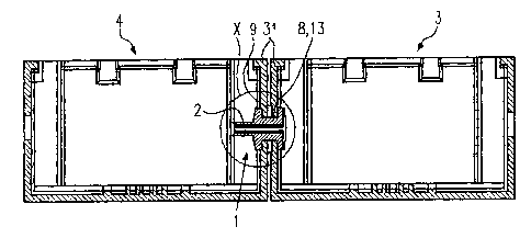
Figure 1 shows a longitudinal section through two adjacently arranged housings
3 and
4, which are each realised in explosion and / or flame-proof protection. In
their opposing
housing walls 31 the two housings 3, 4 have housing bores 8, 9 in which a
cable
bushing device 1 according to the invention is arranged. This is used for the
passage of
appropriate electrical cables 2 between the housings, wherein this bushing is
similarly
explosion and / or flame-proof protected. The housing bore 8 assigned to the
housing 3
has an internal thread 13, to which a corresponding external thread, refer to
the
following figures, of the cable bushing device 1 is screwed. A spacing element
17, refer
also to the following figures, which is part of the cable bushing device 1, is
arranged
between the two housing walls 31.
CA 02603134 2007-10-01
7
For simplification the electrical cables 2 are shortened and other devices in
the
housings 3 and 4 are not illustrated.
The following figures show an enlarged illustration of the detail "X" from
Figure 1 in
which an embodiment of the cable bushing device 1 according to the invention
is
illustrated.
The same parts are each identified in the following figures by the same
reference
numerals and are sometimes only mentioned in connection with a figure.
Figure 2 is an external view of the cable bushing device 1 illustrated without
parts of the
housings 3 and 4.
The cable bushing device 1 has an external body 5, refer also to Figure 3,
from which a
spacing element 17 protrudes radially outwards at about the middle. Said
element is
formed essentially as an annular shaped circumferential edge flange 18. On the
two
side faces 19, 20 of the edge flange 18 sealing elements 21, 22, refer also to
Figure 3,
are arranged in corresponding retaining recesses 23. The edge flange 18 is,
refer to
Figure 1, arranged between the opposing housing walls 31 and seals them
relative to
the housing bores 8, 9 via the corresponding sealing elements 21, 22.
The external body 5 has a first end section 6 which is assigned to the housing
3 and a
second end section 7 which is assigned to the housing 4. On the first end
section 6 an
external thread 14 is provided, refer also to Figure 4, which engages the
corresponding
internal thread 13 according to Figure 1 in the housing wall of the housing 3.
It is
possible to screw the external body 5 into the corresponding housing bore 8
using these
two threads 13, 14. This occurs until the edge flange 18 is in contact with
its
corresponding side face 19 against the outer side of the associated housing
wall 31.
Furthermore, to fasten the external body 5 in this corresponding position a
mounting nut
15 is used which is part of a fixing device 11. The mounting nut 15 is screwed
onto the
external thread appropriately in the first end section 6. Furthermore, a
spring washer 30
CA 02603134 2012-07-19
77525-10
8
is arranged as spacing part 29 between the mounting nut and an inner side of
the
housing wall, refer also to Figure 1.
A limit-stop nut 28 is arranged as limit-stop element 16 on the second
end section 7 as a further part of the fixing device 11. Analogous to the
mounting nut
15 on the second end section 7, this nut can be screwed on by means of a
corresponding external thread. A spring washer 30 is positioned as spacing
part 29
also between the limit-stop nut 28 and a corresponding inner side of the
associated
housing wall, refer to Figure 1.
In Figure 3 a longitudinal section through the cable bushing device 1
according to Figure 2 is illustrated. An insert 12 is arranged within an axial
opening
10 which extends through the complete external body 5 in the axial direction
34. This
insert is in particular arranged detachably within the external body 5. The
insert 12
has recesses 24, through which the appropriate electrical leads 2 are passed
or are
at least arranged with flat plugs 26 as part of a plug connection device 27.
For this
purpose the recesses 24 have insertion openings 25 in which the flat plugs 26
are
inserted and held there. One free end of the respective flat plug 26 protrudes
from
the corresponding insertion openings 25 opposite to the electrical cables 2
illustrated
in Figure 3 and is used for the connection of flat receptacles, which are not
illustrated,
to further electrical cables, which together with the flat plugs form the
corresponding
plug connection device 27. In the illustrated embodiment the insert 12 has a
total of
six recesses 24, running essentially in an axial direction 34, with
corresponding
insertion openings. However, also other inserts 12 can be used, which have
more or
fewer recesses and also have channel shaped recesses directly for the passage
of
electrical cables without the use of corresponding plug connection devices.
In Figure 3 it can also be seen how the edge flange 18 protrudes
radially outwards from an outer side 35 of the external body 5 and surrounds
the
external body 5 in an annular shape. The corresponding side faces 19, 20 are
arranged spaced to spring washers 30 each with the associated nut 15 or 28,
CA 02603134 2012-07-19
77525-10
9
wherein between these the housing walls, refer to Figure 1, are accommodated
in the
cable bushing device 1 in the housing bores 8, 9.
According to the invention only one external thread 14 is provided on
the external body 5 for fastening to a corresponding internal thread 13 of a
housing
bore 8. On the other end section 7 there is no external thread 14 of this
nature and
instead the corresponding region of the second end section is only inserted
into the
associated housing bore 9 so that wider tolerances are possible in the
manufacture of
a housing bore of this nature and optionally also certain deviations in the
alignment of
the housing bores 8 and 9 are possible when inserting the cable bushing device
1.
Only a corresponding external thread for the attachment of the limit-stop
nut 28 is provided at the free end of the second end section 7.
In Figure 4 a perspective view on a cable bushing device according to
Figure 2 is illustrated from a diagonally frontal position, wherein a second
cable
bushing device 1 is positioned directly adjacent to it. They are of the same
type of
construction, refer also to the previous description.
In Figure 4 it can be seen how fastening of the cable bushing device 1
to the housing walls 31 occurs by screwing the nuts 15 and 28, wherein the
corresponding edge flange 18 is arranged between these housing walls. With its
circumferential sealing elements 21, 22, which are formed as 0-rings, the edge
flange 18 is in contact with the corresponding outer sides of the housing
walls 31. An
essentially circular indentation 36, which is used for the partial
accommodation of the
edge flange 18, can be provided in the facing outer sides of the housing walls
31.
Thus, the sealing effect between the housing wall and edge flange with the
sealing
elements situated between them is further improved.
The external body 5 has, on its end sections 6, 7, at least two
opposingly situated flat regions 32, 33 on its outer side 35 (see Figure 3).
CA 02603134 2012-07-19
77525-10
9a
In the following the insertion of a cable bushing device according to the
invention is briefly described based on the included figures.
The cable bushing device 1 is screwed into the housing bore 8 with
internal thread 13 by means of the external body 5 and the corresponding
external
thread 14 on the first end section 6. The screwing-in action takes place until
the edge
flange 18 is in contact with the outer side of the corresponding housing wall
31.
Then, the spring washer 30 as the spacing part 19 can be placed in position
from the
inner side of the housing wall 31
CA 02603134 2007-10-01
,
and can be pressed onto the housing wall 31 by means of the mounting nut 15,
wherein
at the same time fastening of the cable bushing device 1 on the housing 3
occurs. The
other housing 4 with the corresponding housing bore 9 is then pushed onto the
second
end section 7, wherein also certain deviations in the alignment of the housing
bore 8, 9
can be tolerated due to the lack of a screwed joint between the second end
section 7
and the housing bore 9. After pushing on the corresponding housing bore 9 the
other
spring washer 30 is pushed onto the second end section 7 and fixing of the
spring
washer and fastening of the cable bushing device relative to the housing 4
occurs by
means of screwing on the limit-stop nut 28.
Due to the detachable fastening of the insert 12 within the external body 5
the insert
together with the flat plugs 26 which it holds and the corresponding
electrical cables 2
can only be inserted now at this point. There is of course also the
possibility of
arranging the insert 12 in the external body 5 already when fastening the
external body
5 on the housing 3 or of having already arranged it previously.
The cable bushing device is then completed by plugging on appropriate further
electrical
cables with flat receptacles from the housing 3 which together with the flat
plugs 26 form
a corresponding plug connection device 27 for the connection of electrical
cables 2.
The flat plugs 26 are held within the corresponding slot shaped insertion
openings 25
where they can be detachably fastened. There is also the possibility that the
flat plugs
26 are encapsulated within the insert 12 at their ends facing the electrical
cables 2, refer
to Figure 3, to optionally improve the explosion and / or flame-proof
protection. The free
ends of the flat plugs 26 which are passed through the insertion openings 25
are not
potted, because it is there that the corresponding flat receptacles are
plugged on.