Note : Les descriptions sont présentées dans la langue officielle dans laquelle elles ont été soumises.
CA 02604083 2007-10-09
200510034
1
METHOD FOR THE CONTINUOUS PRODUCTION OF METHYL MERCAPTAN
The invention relates to a process for the continuous
production of methyl mercaptan by reacting a starting gas
mixture of methanol and hydrogen sulphide in the gas phase
at a reaction temperature of between 200 and 600 C and an
operating pressure of 1.5 to 40 bar on a catalyst in a
multi-bed reactor.
Methyl mercaptan is an industrially important intermediate
for the synthesis of methionine and for the production of
dimethyl sulphoxide and dimethyl sulphone. Methyl mercaptan
is mainly produced from methanol and hydrogen sulphide by
reaction on a catalyst consisting of an alumina support and
transition metal oxides and basic promoters. The synthesis
of the mercaptan is usually carried out in the gas phase at
temperatures between 300 and 500 C and at pressures between
1 and 25 bar. The reaction of hydrogen sulphide and
methanol to give methyl mercaptan is an exothermic process.
DE-C 196 54 515 describes, for example, a process for the
production of methyl mercaptan in a tube bundle reactor, in
which the liberated heat of reaction is dissipated by means
of a salt melt and is then utilized indirectly by means of
heat exchangers for the evaporation of methanol.
In addition to the methyl mercaptan formed and water, the
product gas mixture contains the unreacted starting
substances methanol and hydrogen sulphide and, as by-
products, dimethyl sulphide and dimethyl ether, and in
small amounts also polysulphides (dimethyl disulphide). In
accordance with the reaction, inert gases such as, for
example, carbon monoxide, carbon dioxide, nitrogen and
hydrogen are also present in the product gas.
The methyl mercaptan formed, as explained in DE 17 68 826,
is separated off from the product gas mixture in a number
of distillation and scrubbing columns at temperatures
between 10 and 140 C.
CA 02604083 2007-10-09
200510034
2
The reaction according to GB 14 17 532 can be carried out
in a fixed bed reactor containing a number of catalyst beds
or in a number of consecutive reactors. Methyl mercaptan is
prepared here by the reaction of a mixture of methanol with
hydrogen sulphide in a molar ratio of 1.10 : 1 and 2.5 : 1,
both reaction components being fed to the reactor
separately. According to FR 24 77 538, for the production
of methyl mercaptan fresh hydrogen sulphide gas is
compressed to 11 bar in a compressor. Afterwards, cycle gas
led back from the process, which contains hydrogen
sulphide, dimethyl sulphide, methanol and small amounts of
methyl mercaptan, is mixed with the compressed hydrogen
sulphide for the formation of the starting gas mixture and
this is heated to 510 C. Before entry into the first of up
to 10 reactors connected in series, the washing agent cycle
stream, which contains methanol and dimethyl sulphide, is
admixed to the starting gas mixture, whereby the reaction
entry temperature falls to 450 C. Before the second and the
following reactors, further methanol, partly as a liquid
and partly as a gas, is injected into the gas stream.
DE-C 11 34 368 relates to the use of a tube bundle reactor
for the production of methyl mercaptan. The reactor
consists of a cylindrical container, in which the catalyst
tubes are arranged parallel to one another. The catalyst
tubes are welded below and above with tube cover plates, as
in tube bundle heat exchangers, the intermediate spaces
between the tubes being filled with heat-conducting fluid.
Each catalyst tubes is provided at its lower end with a
screen, which carries the particulate catalyst.
DE 196 54 515 relates to a process for the production of
methyl mercaptan, in which the energy needed for the
evaporation of the methanol is partly introduced by
utilization of the heat of compression of the hydrogen
sulphide gas and by the heat content of the product gas
leaving the reactor. The heat of reaction is utilized here
CA 02604083 2007-10-09
200510034
3
in order to heat the starting gas mixture to the reaction
temperature with the aid of an external gas heater.
The economy of the overall process depends crucially on the
reaction of the starting gas mixture in a suitable pressure
reactor and the preparation of this gas mixture. For
example, large electrical powers are needed for the
operation of the compressors and of the heating and cooling
circuits. Further, expensive changes of catalyst in tube
bundle reactors on account of long stoppage times represent
a time and cost factor which is not to be neglected.
The object of the invention is the provision of an economic
process for the production of methyl mercaptan.
The invention relates to a process for the continuous
catalysed production of methyl mercaptan by reaction of
methanol and hydrogen sulphide in the gas phase at a
temperature of 200 to 600 C, in particular 250 to 500 C and
a pressure of 1.5 to 40 bar, where
a) the total amount of catalyst is distributed equally or
unequally to at least two, preferably at least three,
zones which are separate from one another,
b) the first of these zones is supplied with a gaseous
mixture comprising methanol and hydrogen sulphide
(starting gas),
c) between the first, the second and optionally the
further zones, methanol is fed in in liquid and/or
gaseous form, and
d) the methyl mercaptan formed is separated off,
the overall molar ratio of the amounts of hydrogen
sulphide and methanol employed amounting to 1:1 to
10:1, preferably 1:1 to 5:1, particularly preferably
1.1:1 to 3:1.
CA 02604083 2007-10-09
200510034
4
The gaseous mixture of hydrogen sulphide and methanol
(starting gas) contains these two compounds in a molar
ratio of 1.1:1 to 20:1, preferably 1.1:1 to 10:1, in
particular 3:1 to 10:1 and optionally by-products from the
reaction and inert gases, if, for example, unreacted
components are separated off from the product gas stream
together with these compounds and recycled.
The use of this starting gas guarantees even in the first
catalyst bed thorough mixing of the reactants and a heat of
reaction, generated by the high conversion, which is
employed for the evaporation of the methanol fed in after
the first zone. If, as customary according to the prior art
(GB 14 17 532), methanol is fed in even before the first
zone, evaporation energy must additionally be supplied.
Likewise, the methanol fed in between the zones containing
the catalysts can contain sulfur-containing starting
materials or products, but consists essentially (in general
> 90 mol%) of methanol.
Preferably, an operating pressure of 2.5 to 25 bar is set.
The compression of the starting gases to the operating
pressure is carried out in one or more stages.
In the first catalyst-containing zone, the hydrogen
sulphide is always present in an excess compared to
methanol.
The total amounts of the methanol fed in in the starting
gas and between the zones are in the ratio from 1:1 to
1:10, preferably 1:2 to 1:7.
Preferably, grid reactors are employed which contain 2 to
25 catalyst beds (zones), in particular 3 to 10, preferably
3 to 8.
At the same time, also at least two of these reactors can
be connected to one another.
CA 02604083 2007-10-09
200510034
Grid reactors allow the direct metering in of gaseous and
liquid methanol, hydrogen sulphide or a starting gas
mixture containing, inter alia, methanol and hydrogen
sulphide between the catalyst beds (grids), where the heat
5 of reaction liberated in the grids is utilized directly for
the evaporation of the methanol, and the temperature of the
gas mixture drops before entry into the next grid. As a
result of this concept, powerful methanol evaporators can
be dispensed with. The economy of the overall process is
also made possible in comparison with tube bundle reactors
(with thousands of individual tubes to be filled and
emptied), by more rapid modular catalyst exchanges in the
grids. Thus the catalyst of each grid can be exchanged
separately. This is particularly advantageous if the
deactivation of the catalyst, as in the synthesis of methyl
mercaptan, is dependent on the concentrations of the
reactants and thus on the site or reaction progress.
Furthermore, the use of various catalysts in a reactor is
facilitated thereby.
As a result of the use of the grid reactor, especially in
reactions with very strong evolution of heat, such as, for
example, the synthesis of methyl mercaptan from methanol
and hydrogen sulphide by means of catalysts customary for
the process, excellent temperature control is possible by
choice of the grid size and the amount of injected liquid.
By this means, in the synthesis of methyl mercaptan, high
excess temperatures, which lead to decreased yields and to
an increased deactivation of the catalyst, can be avoided.
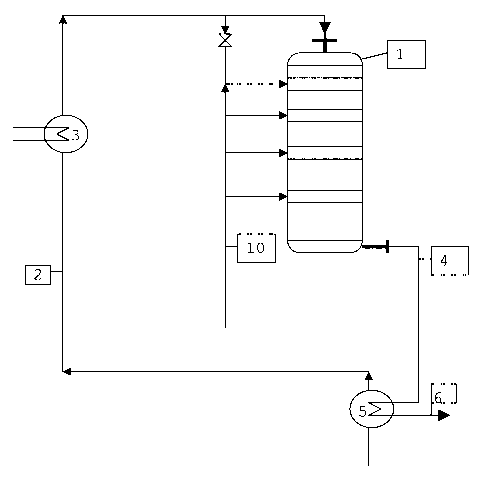
Figure 1 and Figure 2 serve for the further explanation of
the process using the preferably employed grid reactor.
Figure 1 shows a process scheme of the first section of the
production process of methyl mercaptan.
Figure 2 shows a detail representation of a grid reactor
used in this process.
CA 02604083 2007-10-09
200510034
6
Figure 1 shows a process scheme for the first section of
the methyl mercaptan production, which comprises the
starting gas preparation, the reaction in the reactor and
the cooling of the product gas mixture. The reaction in the
grid reactor 1 is carried out on customary catalysts,
preferably on alumina, as a carrier, which are preferably
coated with alkali metal tungstate, in particular caesium
tungstate. The catalysts are described in the applications
WO 2005/021491, DE 10 2004 77 39 and DE 10 2004 061 016.
Catalysts of this type are able to react a starting gas
mixture having a molar ratio of hydrogen sulphide to
methanol of 1.5 : 1 to 10.0 : 1 at an operating pressure of
5-20 bar, a reaction temperature of 280 - 450 C and at a
loading with a space rate GHSV of 300-2000 h"lwith a
methanol conversion and a selectivity of in each case more
than 90 % to give methyl mercaptan. The process according
to the invention also allows the preparation of methyl-
mercaptan using otherwise customary catalysts.
On account of the very active catalysts for the synthesis
of methyl mercaptan, which especially contain halide-free
alkali metal tungstates, halide-containing alkali metal
tungstates or preferably halide-free or -containing caesium
tungstates as promoters, an excellent temperature control
for the operation of these catalysts at the yield optimum,
without an increased deactivation of the catalyst having to
be feared, is necessary. This is made possible when using
these and other customary catalysts and carrying out
according to the invention the synthesis in a grid reactor.
The starting gas mixture 2 consisting of methanol vapour,
hydrogen sulphide and optionally further of the above-
mentioned components is heated in the gas heater 3 to the
reactor entry temperature (pre-temperature) of 100-350 C.
The starting gas mixture reaches the grid reactor at this
temperature.
CA 02604083 2007-10-09
200510034
7
On account of the quantitative proportion of methanol and
hydrogen sulphide, the starting gas mixture cannot be
confused with a hydrogen sulphide gas which contains small
amounts of methanol as a result of recycling.
The gas mixture is dispersed uniformly over the catalyst
bed of the first reactor grid by means of dispersing
devices. For better heat transfer, the catalyst bed of the
first reactor grid is optionally covered with a layer of
inert, solid packing materials, at least in the area of the
entry of the gas stream. Advantageously, for this, for
example, packing material spheres of ceramic, silica or
alumina are used. The grid reactor in general contains 2 to
25 catalyst beds, advantageously 2 to 10 catalyst beds,
preferably 3-8, are accommodated in one apparatus. Between
the grids, liquid or optionally gaseous methanol,
optionally also hydrogen sulphide or the starting gas
mixture 2 is metered into the process. Methanol is
preferably fed to the process in liquid form between all
grids or some of the grids. At the same time, the heat of
reaction which is released in the grid situated before the
injection site is utilized for the evaporation of the
methanol and for the control of the temperature in the
strongly exothermic reaction.
A lengthening of the bed length of the catalyst grids or an
increase in the amount of catalyst from the first to the
last grid (zone) in the flow direction has proved
advantageous. Optionally, no methanol is fed in before the
last grid.
Between the catalyst grids are optionally situated devices,
such as, for example, static mixers, ordered or disordered
packings, which make possible a turbulent flow course and a
uniform dispersion and mixing of the reactants. Preferably,
the starting gas mixture optionally metered in between the
catalyst grids and/or the liquid methanol is dispersed
radially, tangentially or zone-wise over the catalyst bed
CA 02604083 2007-10-09
200510034
8
by means of a gas disperser, so that a uniform turbulent
flow distribution and complete mixing of the reactants
results. The mixing of the reactants can be improved by
optional introduction of inert layers of packing materials.
The catalyst grids are advantageously designed as catalyst
beds having radial, square or polygonal geometry, other
geometries also being possible. The grids can individually
be filled with catalyst or emptied. Preferably, they are
designed such that they can be removed from the reactor in
modular form. Alternatively, in each case a detachable or
undetachable connection or opening in the reactor wall can
be utilized for the simple exchange of the catalyst.
In a further embodiment of the invention, the grids are
filled with at least two different catalysts. The
dependence of the local yield and local selectivity,
especially in the synthesis of methyl mercaptan, is thus
taken into account as a function of the concentrations of
the reactants and thus the progress of the reaction. For
example, it is advantageous in the synthesis of methyl
mercaptan to fill the last grid with a very active catalyst
if a complete conversion of methanol is desired. If the
reaction is to be operated with respect to maximum
selectivity, a less active, but for this very selective
catalyst can be employed in the last grid. The grid reactor
thus makes possible, by means of simple, site-dependent
filling, flexibility in the production of methyl mercaptan.
The product gas mixture 4 leaves the reactor at the
reaction temperature of the last grid. Its heat content can
be utilized in the heat exchanger 5 for the evaporation of
methanol or for the production of steam etc. In this
process, the product gas mixture cools to approximately
150 C and is fed to the second process section as a volume
flow 6. The separation of the product gas mixture into its
CA 02604083 2007-10-09
200510034
9
components is performed in the second process step of the
methyl mercaptan production. The separation can be carried
out according to various, known processes. A particularly
advantageous separation of the product gas mixture is
described in German patent specification DE-C 196 54 516.
The leading back of the hydrogen sulphide separated off in
the second process step as a cycle gas stream is important
for the economy of the process. The same applies for the
methanol separated off from the product gas mixture and not
completely consumed in the reaction in the reactor, and for
the wash methanol optionally used in the second process
step.
Fig. 2 shows the preferred embodiment of the reactor,
according to Claim 1. In the reactor 1, n (n = 2-25)
catalyst beds are accommodated. Preferably, 3-10 catalyst
beds (grids) are used. The starting gas mixture 2 enters
through the distributor space 7 into the first catalyst bed
8. This first catalyst bed is optionally first covered with
a packing of inert materials in the flow direction of the
starting gas. For example, alumina spheres or ceramic
Raschig rings are used as inert materials. Subsequent to
the inert layer is situated the catalyst packing. As a
result of the strongly exothermic formation of methyl-
mercaptan, in the course of this the temperature in the
adiabatic grid increases greatly. After leaving the first
grid, the gas mixture is enriched in the distributor space
9 with liquid methanol 10, hydrogen sulphide 10 or
optionally the starting gas mixture 2. As a result of the
heat of reaction of the first grid, the liquid methanol
evaporates without further supply of heat. By this means,
the temperature of the gas mixture drops. The gas mixture
subsequently flows from the distributor space 9 into the
second catalyst bed 11, devices in the distributor space 9
providing for a turbulent flow and a complete mixing of the
reactants, which is distributed uniformly to the entire
surface of the second catalyst bed. The supply of liquid
CA 02604083 2007-10-09
200510034
methanol or optionally hydrogen sulphide or starting gas
mixture takes place analogously at n-1, preferably n-2,
injection sites between the following catalyst beds of the
grid reactor. Optionally, a supply of liquid methanol,
5 hydrogen sulphide or starting gas mixture before the last
catalyst bed at the injection site 12 can be dispensed with
in order to obtain a complete conversion of methanol in the
reaction.
After leaving the grid reactor, the reacted gas mixture is
10 fed to further processing via the collecting space 13 as a
product gas stream 4.
Thus, the temperature of a strongly exothermic reaction can
be excellently controlled in only one reaction apparatus
including an integrated direct heat exchange without
additional heat carrier media such as salt melts or steam.
The process scheme shown in Fig. 1 contains the necessary
components for carrying out the process according to the
invention.