Note : Les descriptions sont présentées dans la langue officielle dans laquelle elles ont été soumises.
CA 02604662 2007-09-27
EXTERNAL ACCESS TO METER DISPLAY
CROSS-REFERENCE TO RELATED APPLICATIONS
[0001] This application claims the benefit of earlier filed U.S.
provisional
application no. 60/847,721, filed September 28, 2006.
HELD
[0002] This application relates to the field of utility metering, and
more
particularly, to utility meters having external communications capability.
BACKGROUND
[0003] Utility meters typically include a metering circuit that is
capable of
measuring some aspect of a consumed commodity and a display that provides
visual
information regarding the measured consumption. For example, in electricity
meters, a
metering circuit measures electrical energy delivered to a customer or load,
and the
display provides visual information regarding the measured energy data. While
many
simple meters continue to use rotating disks and mechanical displays, many
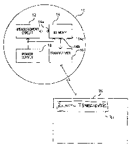
newer meters
employ electronic displays such as LCD or LED displays.
[0004] In meters having electronic displays, the meter is programmed to
display
information generated within the metering circuit. To this end, the metering
circuit may
write data to memory in certain locations and in a certain way, and then a
processing
circuit (which may be part of the metering circuit) displays the data written
to the
1
CA 02604662 2007-09-27
memory locations in a predetermined sequence according to a standard meter
display
routine.
[0005] The standard meter display routine specifies what meter data will
be
displayed and in what format. The data that may be displayed by a typical
utility meter
with and electronic display is limited to the data that is generated by the
meter or
otherwise contained within the meter. Although some meters are configurable,
the meter
is typically only configurable to the extent that the display functionality is
selected from a
set of functions supported by the meter's firmware. When the meter is
configured for use
in the field, a meter operator, such as a utility employee, selects certain
functions and
parameters for the meter's standard display routine from a set of standard
functions and
parameters pre-programmed into the firmware of the meter. Once the meter is in
the
field, the meter may be re-configured to alter the meter display routine by
selecting
additional or different functions, data, or parameters found within the meter.
However,
the display of the meter is limited to the meters existing programming, and
typical meters
are not equipped to display data from a source external to the meter and/or
with functions
and parameters not found in the meter firmware. The meter's display
limitations reduce
the overall functionality of the meter and ability to work effectively with
remote sources
external to the meter.
[0006] Accordingly, it would be advantageous to provide a utility meter
that
provides the ability to display a message received from a remote source
outside of the
utility meter after the meter is placed in the field. In addition, it would
also be
advantageous to provide a utility meter that can deliver data to a remote
location for
processing and receive processed or compiled data in return that may then be
displayed
2
CA 02604662 2015-01-21
77543-49
by the utility meter. It would also be advantageous if such a utility meter
included
protection measures to ensure that only certain parties have certain limited
abilities to
alter the meter's display.
SUMMARY
[0007] As disclosed
herein, a utility meter comprises a measurement circuit
configured to measure consumption data and a memory configured to store meter
data
including the consumption data. The meter further comprises a receiver
configured to
receive a priority message from a source external to measurement circuit or
the utility
meter. In addition, the meter comprises a meter display comprising a plurality
of display
segments. The meter display is configured to display the meter data according
to a
standard meter display routine. The meter display is further configured to
display the
priority message on at least a first portion of the plurality of display
segments such that
meter data normally displayed during the standard meter display routine is not
displayed
on the first portion of the plurality of display segments. The utility meter
further
comprises a controller configured to determine whether the standard meter
display
routine should be interrupted or overridden in order to display the remote
message.
=
3
CA 02604662 2015-01-21
77543-49
[0007a] According to an embodiment, there is provided a method of
operating a utility
meter including metrology circuitry and a meter display, the method
comprising: a) displaying
meter data on the meter display according to a standard meter display routine,
the meter data
including data from the metrology circuitry; b) receiving a message and a
password at the
utility meter from a source external to the metrology circuitry; c) setting a
flag based on a
determination of the received password; d) displaying the at least a part of
the received
message instead of the meter data in the first location on the meter display;
and wherein
displaying the at least part of the received message includes interrupting or
overriding the
standard meter display routine responsive to a determination that the flag is
set in order to
display the received message.
[0007b] According to another embodiment, there is provided a utility
meter comprising:
a measurement circuit configured to measure consumption and provide
consumption data; a
memory configured to store meter data, the meter data including the
consumption data; a
receiver configured to receive a message from a source other than the
measurement circuit; a
meter display a processing device configured to cause the meter display to
display the meter
data according to a standard meter display routine, the processing device
further configured to
cause the meter display, responsive at least in part to receiving the message,
display the
received message in a location in which the meter data was previously
displayed such that
meter data previously displayed during the standard meter display routine is
not displayed on
the meter display.
[0007c] According to another embodiment, there is provided a method of
operating a
utility meter including a meter display, the method comprising: a) displaying
consumption
data on a first portion of the meter display; b) receiving a priority message
at the utility meter
from a remote source external to the utility meter, and receiving display
parameters associated
with the priority message from the remote source; and c) updating the meter
display to display
the priority message on the meter display using a format corresponding to the
received display
parameters, such that at least part of the priority message replaces the
consumption data on the
first portion of the meter display.
3a
CA 02604662 2015-01-21
77543-49
[0008] The above described features and advantages, as well as others,
will become
more readily apparent to those of ordinary skill in the art by reference to
the following
detailed description and accompanying drawings. While it would be desirable to
provide a
utility meter that provides one or more of the above-mentioned advantageous
features, or
other advantages as may be apparent to those reviewing this disclosure, the
teachings
disclosed herein extend to those embodiments which fall within the scope of
3b
CA 02604662 2007-09-27
the appended claims, regardless of whether they accomplish one or more of the
above-
mentioned features or advantages.
BRIEF DESCRIPTION OF THE DRAWINGS
[0009] FIG. 1 shows an exemplary utility meter arrangement in
communication
with a remote communication device;
[0010] FIG. 2 shows an exemplary embodiment of the utility meter of FIG.
1, the
meter including a memory, a processor, a display, and a transceiver;
[0011] FIG. 3 shows an exemplary embodiment of the structure of the
memory of
FIG. 2;
[0012] FIG. 3A shows an exemplary subroutine operated by the processor of
FIG.
2 when a remote communication device requests access to the memory;
[0013] FIG. 4 shows an exemplary priority message routine operated by the
processor of FIG. 2;
[0014] FIG. 5 shows an exemplary screen shots from a remote computer
operating a priority message program;
[0015] FIG. 6 shows an updated version of the screen shot of FIG. 5
following a
change in an associated meter's display;
[0016] FIG. 7 shows the screen shot of FIG. 5 once a user has input a
priority
message in a priority message input box;
[0017] FIG. 8 shows the screen shot of FIG. 5 after the priority message
has been
sent to the associated meter;
4
CA 02604662 2007-09-27
=
[0018] FIG. 9 shows an updated screen shot of FIG. 8 with the
priority message
scrolling across the screen; and
[0019] FIG. 10 shows yet another updated screen shot of FIG. 8
with the priority
message scrolling across the screen.
DESCRIPTION
[0020] Various embodiments of a utility meter with novel display
capabilities are
disclosed herein. According to at least one first embodiment, the display
capability of an
electricity meter is expanded by allowing alternative device display control
that overrides
the ordinary display program within the meter. The alternative or instant
device display
control may be activated through an external communication interface such as
an optical
port in the meter housing or an automatic meter reading ("AMR") device such as
a radio,
power line modem, or land-line modem.
[0021] In another embodiment, the meter memory includes
locations reserved for
access by different users or devices having different passwords. The metering
processor
can perform display operations using information from the different user-
allocated
memory locations.
[0022] Although various embodiments of a utility meter are
disclosed herein, it
will be recognized that features from various embodiments may be combined in
an
advantageous manner.
[0023] With reference now to the drawings, FIG. 1 shows an
exemplary utility
meter 10 configured for operation according to the present invention and an
exemplary
remote source 30 external to the utility meter but in contact therewith. In
general the
CA 02604662 2007-09-27
remote source 30 is configured to communicate data to and/or from the utility
meter 10.
The utility meter 10 includes metrology circuitry in the form of a measurement
circuit 12,
a memory 14, a communication device, such as a transceiver 16, and a power
supply 18.
It will be appreciated that the utility meter 10 may optionally include other
devices such
as other communication circuitry, an electronic or mechanical display, and
other
peripheral devices commonly available in utility meters.
[0024] The exemplary remote source 30 includes a transceiver 31 and is
operable
to transmit data to or receive data from the utility meter 10. Accordingly,
the remote
source may transmit data through a wireless transmission or via a wired
connection, such
as an interne connection. The remote source is external to the utility meter,
and may be
any of numerous sources, such as, for example, a handheld transmission device,
a mobile
computer, or a stationary computer located at particular location, such as the
offices or
production plant of a utility.
[0025] Referring specifically to the utility meter 10, the measurement
circuit 12 is
a circuit that generates utility data. The utility data may be in the form of
digital signals,
such those as used within processing circuitry, or may include pulses
representative of a
particular quantity of commodity consumed. For example, in water and gas
meters,
circuitry connected to flow metering devices generate pulse signals, each of
which
represents a certain amount of flow. In electricity meters, the measurement
circuit 12
may include one or more processing devices that calculate energy consumption
data from
measured current and voltage signals. Measurement circuits used in
electricity, gas and
water metering are known in the art.
6
CA 02604662 2007-09-27
[0026] The memory 14 in the exemplary embodiment of FIG. 1 is a non-
volatile
memory that retains data even in the absence of electrical bias power. Thus,
the non-
volatile memory 14 may be an electrically erasable programmable read-only
memory
("EEPROM"). The non-volatile memory 14 is operably coupled to communicate data
to
and/or from the measurement circuit 12. The non-volatile memory 14 is further
operable
to communicate data to and from the meter transceiver 16. To this end, the non-
volatile
memory includes multiple communication ports, specifically a first port 14a
coupled to
the measurement circuit and a second port 14b coupled to the meter transceiver
16.
[0027] The power supply 18 is a device that generates bias power for the
measurement circuit 12. In one example, the power supply 18 may be connected
to the
mains electrical power lines and generate bias power for the measurement
circuit.
However, the power supply 18 may alternatively derive power from batteries,
light
sources or the like. In accordance with embodiments of the present invention,
the power
supply 18 provides the power necessary to allow data communication between the
measurement circuit 12 and the non-volatile memory 14.
[0028] The meter transceiver 16 is a transceiver circuit that is
configured to
receive a signal from an external source, obtain energy from the signal, and
convert the
energy to bias power for use by the non-volatile memory 14. To this end, the
meter
transceiver 16 is connected to a bias power input 14c of the non-volatile
memory 14. In
addition, the meter transceiver 16 is operable to perform a data transfer
operation
responsive to the signal, the data transfer operation including a transfer of
data between
the non-volatile memory 14 and the meter transceiver 16 using the second port
14b of the
non-volatile memory 14.
7
CA 02604662 2007-09-27
The transceiver 16 is, for example an RF transceiver, and thus is operable to
perform the
above-described functions upon receiving an RF signal.
[0029] Fig. 2 shows a more detailed view of an exemplary electricity
meter 100
configured for use according to at least one embodiment of the present
invention. The
electricity meter 100 shows in further detail one example of the meter 10
shown in Fig. 1.
[0030] Referring now to Fig. 2, a schematic diagram of an exemplary meter
suitable for practicing the present invention is shown. For purposes of
explanation and
example only, the meter of Fig. 2 is shown as an electrical utility meter for
monitoring
three-phase electrical power. However, the principles disclosed herein are
applicable to
other types of meters, electrical meters and otherwise.
[0031] In Fig. 2, the exemplary meter 100 is a meter intended to, among
other
things, measure power consumption by a load, not shown, connected to an
electric utility,
not shown. The exemplary meter 100 includes polyphase current sensors 70, 72
and 74
and polyphase voltage sensors 76, 78 and 80. The meter 100 further includes a
conversion circuit 105, a processor or microcontroller 108, a memory circuit
110, a
display 112, and a communication device, such as a transceiver 114. The
conversion
circuit 105 comprises a first multiplexer 116, a second multiplexer 118, a
first analog-to-
digital ("A/D") converter 122, a second AID converter 124, and a digital
signal processor
("DSP") 128. It will be noted that a three-phase electrical utility meter is
given by way of
example only. Those of ordinary skill in the art may readily adapt the
inventive aspects
of the disclosed embodiment to other types of meters, such as single phase or
network
meters.
,
8
CA 02604662 2007-09-27
[0032] The
meter 100 further includes a power supply 133 that is configured to
generate bias power for the conversion circuit 105, the controller 108, the
memory circuit
110, the display 112, and the transceiver 114. Such a power supply 133 may
suitably be
a switched mode power supply circuit that converts line voltage received from
one of the
mains electrical power lines to suitable DC bias voltages. Such circuits are
known to
those of ordinary skill in the art.
[0033] The
current sensors 70, 72 and 74 are each connected to receive signals
indicative of the current flowing through one phase of a three phase power
line (i.e.,
phase A, phase B, and phase C). The current sensors 70, 72 and 74 of the
exemplary
embodiment described herein preferably each include transformers (not shown in
Fig. 2),
which are advantageously situated to detect current on each respective phase
of the power
line. The current sensors 70, 72 and 74 are further connected to the
conversion circuit
105 through the first multiplexer 116.
[0034] The
voltage sensors 76, 78 and 80 are each connected to the respective
phase of the power line (i.e., phase A, phase B, and phase C) to obtain a
voltage
measurement therefrom. To this end, the voltage sensors 76, 78 and 80 may
suitably
comprise high resistance voltage dividers. Alternatively, the voltage sensors
76, 78 and
80 may be potential transformers. The voltage sensors 76, 78 and 80 are
further
connected to the conversion circuit 105 through the second multiplexer 118.
[0035] The
conversion circuit 105 is a circuit operable to receive polyphase
voltage and polyphase current measurement signals and generate digital signals
therefrom, the digital signals including a power consumption signal and
voltage and
current signals. In the exemplary embodiment described herein, the conversion
circuit
9
CA 02604662 2007-09-27
105 comprises first and second multiplexers 116 and 118, respectively, the
first and
second A/Ds 122 and 124, respectively, and the DSP 128. The above listed
components
of the conversion circuit 105 may suitably be incorporated onto a single
semiconductor
substrate.
[0036] The controller 108 is operably configured to, and executes
programming
instructions to, receive the digital signals from the conversion circuit 105,
monitor and
record power consumption using the digital signals, and analyze the digital
voltage and
current measurement signals and associated phase angle data to determine
whether one or
more measurement errors is present. The controller 108 may suitably be, for
example, a
KO series microcontroller available from NEC. However, the controller 108 may
alternatively comprise any other suitable processing device or circuit. The
controller 108
generally includes firmware, or in other words, an integrated memory into
which
programming instructions are stored. Alternatively, the programming
instructions may
be stored in the memory 110.
[0037] The memory 110 is configured to store data, and the controller 108
is
configured to deliver data to the memory or retrieve data from the memory. As
discussed
above, the memory 110 may be a non-volatile memory.
[0038] With reference to FIG. 3, the memory 110 may be segmented with
different memory segments 141-145 storing different types of data. Each
segment of the
memory is reserved for a particular user or purpose as set forth below.
[0039] A first segment 141 of the memory 110 is dedicated to the storage
of
passwords and associated memory segments. The contents of the memory 110 may
only
be accessed and/or modified upon presentation of a proper password that
provides access
CA 02604662 2007-09-27
to the particular memory location. In at least one embodiment, different
passwords
contained in the first segment are associated with one or more of the
different memory
segments. In this case, a user external to the meter 100 is only granted
access to a
memory segment upon entry of a password associated with that memory segment.
Thus,
a user's ability to read data from or write data to a given memory segment is
dependent
upon the user's password. For example, one or more first passwords may be
granted to
an automatic meter reading (AMR) company. Using the password(s), the AMR
company
would be allowed to read data from the AMR memory, write data to the AMR
memory,
or configure the AMR memory, as will be explained in further detail below with
reference to the fourth memory segment 144. As a further example, the utility
may also
grant one or more second passwords to other meter parties, such as one or more
second
passwords for use by the customer where the meter is located. Such second
passwords
would allow the customer to obtain data from certain memory segments (e.g.,
the second
segment 142) but block access to other memory segments (e.g., the fourth
memory
segment 144). The utility would also have its own set of third passwords that
provide the
utility with access to data in any segment of the memory or certain segments
of the
memory, depending on the access level of the password.
[0040] With
continued reference to FIG. 3, a second segment 142 of the memory
110 is dedicated to metrology data, including various utility measurements
taken by the
meter 100 over a period of time. For example, in an electricity meter, the
measurements
may include time-of-use or peak demand measurements taken by the meter over
the
course of a billing cycle. Other examples of metrology data that may be stored
in an
11
CA 02604662 2007-09-27
electricity meter include kilowatt-hour measurements, reactive power
measurements,
power factor, pricing information, etc.
[0041] The meter 100 is configured to display the metrology data
contained in the
second segment 142 in different forms, depending upon the standard meter
display
routine configured by the user. Thus electronic display of the meter may be
programmed
to display different quantities, such as kilowatt-hours, VARs, VA, error
codes, energy
direction information, and the like, which data may be accessed from memory
segment
142. Those of skill in the art will recognize that the above and other various
types of
meter data and configurations may be selected for display on the meter
display. These
various types and formats of data are generated within the meter and stored in
the meter
memory 110, and particularly meter segment 142. The user or a utility service
person
typically configures the meter to display only selected data from the meter
memory 110
according to a standard meter display routine, as discussed below.
[0042] A third segment 143 of the memory 110 is dedicated to the meter
display.
The meter display memory segment 143 stores a standard meter display routine
which is
configured to display different types of data in differing formats depending
on the display
format desired by the customer or the utility. In at least one embodiment, the
standard
meter display routine comprises a series of display messages, each displayed
sequentially
on the display. For example, the standard meter display routine may be
configured to
cycle the display between an instantaneous or current interval usage
measurement and an
aggregate usage measurement for a billing cycle. As an alternative example,
the standard
meter display routine may be configured to cycle the display between a billing
category
for the current interval, a total usage for the current interval, and a total
energy
12
CA 02604662 2007-09-27
,
consumption amount for the billing cycle. Accordingly, the standard meter
display
routine stored in the meter display segment 143 uses the data stored in the
metrology
segment 142 to provide the desired information to the meter display 110.
[0043] Another example of data that may be stored in the third segment
143 of
the memory relates to different identifiers that are used in association with
displayed
quantities. These identifiers may be letters or numbers and are generally
selected by the
customer to indicate what is being shown on the display. Different identifiers
are
selected for a given standard meter display routine based on the customer's
selected
identifiers. One customer may choose to display letters to indicate a total
energy
consumption while another customer may choose to display a numeric code to
indicate
total energy consumption. The standard meter display routine is programmed to
display
selected identifiers for the customer along with selected metrology data.
[0044] The differing identifiers and differing metrology data types
are but two
examples of different data that may be stored in the third segment 143 of the
memory
110. At the time of initial meter configuration, the meter's standard meter
display
routine is configured to display only selected identifiers and selected
metrology data from
the meter memory. In one meter embodiment, the standard meter display routine
is
configured to show four different data identifiers and associated metrology
data
types/values which are selected from over one hundred different data types
available in
the meter memory. After the standard meter display routine is initially
configured, it may
be altered by the utility to display different data identifiers or metrology
data types stored
in the memory. In at least one embodiment of the meter disclosed herein, the
standard
meter display may be overridden or interrupted to display additional
information
13
CA 02604662 2007-09-27
provided from sources external to the meter and stored in other segments of
the meter
memory 110. This operation of overriding or interrupting the standard meter
display
routine is discussed in further detail below.
[0045] A fourth segment 144 of the memory 110 may be dedicated to memory
for
automatic meter reading (AMR). Data stored in this segment 144 may include
information to be transmitted to an AMR device or information received from an
AMR
transmission device. Examples of data in this fourth segment 144 of the memory
110
include AMR data related to signal strength between the AMR remote
communication
device and the meter, AMR communications history, a meter address on the
network
used by the AMR, rate information from the AMR company, brownout data, etc.
One of
ordinary skill in the art will recognize that an AMR company may wish to
receive and
store numerous other types of data through the fourth segment 144 of the
memory. In at
least one embodiment of the meter disclosed herein, the fourth segment 144 of
the meter
memory 110 is exclusively available to the AMR company. The AMR company may
read data from or write data to the fourth memory segment 144 upon entry of an
appropriate password which is stored in the first segment of the memory and
associated
with the fourth segment of the memory. Such an embodiment is described in
further
detail below.
[0046] A fifth segment 145 of the memory 110 may be dedicated to the
storage of
additional information which is obtained from another source external to the
meter after
the meter is placed in the field. This additional storage segment 145 provides
a quantity
of memory that is exclusively available to a party other than the AMR company.
For
example, the fifth segment 145 may be exclusively available to the utility. As
discussed
14
CA 02604662 2007-09-27
. :
in further detail below, data from a source external to the meter 110, such as
the utility
offices, may be received by the meter 110 at the transceiver 114. The
additional storage
segment 145 may be used to store the data received at the transceiver for
later use by the
meter, such as displaying a priority message on the meter display.
[0047] In at least one embodiment, as discussed above, access to
the data in the
various segments 141-145 of the memory 110 is only available for access by a
user upon
receipt of a proper password. For example, data in the fourth segment 144 may
be
exclusively available to an AMR company. However, before the AMR company may
access the memory in the fourth segment, the AMR company must input a proper
password. Depending upon the access level granted by the password, the AMR
company
may have access to certain other segments of memory also. Thus, if the AMR
company
is the billing company, receipt of the AMR password may also provide the AMR
company with access to data in the second memory segment 142.
[0048] FIG. 3A provides an exemplary subroutine for determining
if access to
certain memory segments should be granted. According to the subroutine, a
memory
access request is received in step 180 accompanied by a password. In step 182
the
subroutine compares the received passwords with the passwords stored in the
first
segment 141 of the memory. If the received password is not a valid password
stored in
the first segment 141 of the memory, an error notice is returned in step 184
denying
access to the memory based on an invalid password. If the received password is
a valid
password, in step 186 the system then determines if the password received
provides
access to the requested memory segment (i.e., if the requested memory address
is in a
memory segment which the password is associated with). If the password does
not
CA 02604662 2007-09-27
provide access to the requested memory segment, an error notice is returned.
On the
other hand, if the password does provide access to the requested memory
segment, the
user is granted access to the memory in step 188, allowing the user to either
read from or
write to the requested memory section.
[0049] Returning again to FIG. 2, the transceiver 114 of the meter 100 is
operable
to transmit signals to and/or receive signals from a remote source outside of
the meter.
Such transceivers are known to those of ordinary skill in the art. In one
embodiment, the
transceiver 114 may be a combination RF transceiver and dual port memory
device,
sometimes known in the art as an RIAD device.
[0050] In at least one embodiment, the transceiver 114 is operable to
transmit
meter data from the meter circuit to a remote device 30 (see FIG. 1), such as
a computer
at a distant utility facility. The transceiver 114 can also receive data
transmitted from the
remote device 30. In accordance with one embodiment, the processing device of
the
metering circuit may at least temporarily display information received from
the remote
device via the transceiver. The transceiver may comprise one or more separate
communications devices configured to communicate with different remote
sources, such
as one communication device to communicate with the utility company and one
communication device to communicate with the AMR company.
[0051] The meter 100 further includes a display 112. The display is an
electrical
display as commonly used in utility meters, such as the seven-segment or
sixteen-
segment LCD or LED display. These and other common displays for utility meters
will
be recognized by those of ordinary skill in the art. In one embodiment, the
display 112 is
comprised of a plurality of sections, such as a first section comprised of
seven-segment
16
CA 02604662 2007-09-27
,
display characters and a second section comprised of sixteen-segment display
characters.
Different types of data may be displayed in each of the sections of the
display, such as
identifiers in one section and associated numerical data in another section.
The different
segments may include different sized characters to assist the reader in
quickly
distinguishing one segment from another segment. Such multiple-section
displays will
also be recognized by those of ordinary skill in the art.
[0052] As discussed above, the display 112 is typically used to show
metrology
data, including usage information related to the utility meter. For example,
in an
electricity meter, usage information may include instantaneous demand
metering, total
interval usage, total billing period usage, current pricing per unit consumed,
etc.
However, situations may exist where it would be advantageous to override a
meter's
electronic display in order to convey information that is useful only for a
particular
instance, such as when a technician or meter reader will be at the meter's
location. The
content of the displayed data is dependent on the situation. The embodiment
described
herein can be used in these situations to update the meter's display.
[0053] In one example of a situation where a utility meter display may
be
overridden, consider an electricity meter that needs to be replaced, and
further consider
that the electricity meter is one of many similar meters in a bank of meters
at an
apartment complex. It would be advantageous to provide an indication on the
meter
display that a particular meter in the bank of meters is the meter that should
be replaced.
On the day that a utility crew is scheduled to replace the meter, the utility
transmits a
priority message that causes the subject utility meter to display a text
message such as
"SWAP OUT 07-25-2006". This priority message is not related to billing or
pricing or
17
CA 02604662 2007-09-27
consumption or other usage, but is instead designed to communicate a
particular message
to someone present at the meter using the meter display. The priority message
is received
by the meter at the transceiver 16, and is stored in the memory 110. In
particular, the
priority message is stored in the fifth segment 145 of the memory 110
specifically
reserved for additional information received by the meter. After the message
is stored in
the memory 110, the processor 108 interrupts or overrides the standard meter
display
routine being operated by the meter, and instead displays the priority message
on the
meter display 112. In this case, the "SWAP OUT" message is displayed. This
message
provides a clear indication to the utility crew that this particular meter
from the bank of
meters is in need of replacement. Without the message, the utility crew would
need to
inspect each meter and look for a matching identifier (serial number or other
identification string) on the meter's nameplate. The manual identification
would be more
time consuming and error prone than providing a priority message on the meter
display.
[0054]
Referring now to Fig. 4, an exemplary priority message routine 200
operated by the processor 108 is shown. In a first step 202 of the priority
message
routine, the meter processor updates displays by executing its standard meter
display
routine. In the standard meter display routine, the meter processor typically
consults a
number of variables or memory addresses that identify data to be displayed, if
at all, in
the different segments of the display. The meter electronic display may have
multiple
segments indicating various types of information. For example, the display may
include
a display segment configured to show an energy consumption quantity (i.e. a
meter usage
value). In addition, the display may include a display segment showing the
type of
service and/or the voltage level. Furthermore, the display may include a
predefined
18
CA 02604662 2007-09-27
,
segment for error codes or messages generated within the meter. As yet another
example,
the display may also include a segment showing the direction of the flow of
energy (to or
from the load). All of the information to be displayed is suitably stored in
select memory
locations.
[0055] In step 204, the meter processor determines whether any flags
for priority
display control (or "instant" or "override" display control) have been
received. If not, the
meter processor returns to update the display per normal operation in step
202. If so,
however, then the meter proceeds to step 206. In at least one embodiment, the
priority
flag is only set if a proper password has been received from the remote source
wishing to
override the display.
[0056] In step 206, the meter processor obtains the priority display
information
including (i) an identification of the information to be displayed, and (ii)
the segment in
which the information should be displayed. In some embodiments, more, less or
different
details regarding what is to displayed, where or how (which segments) it is to
be
displayed, and how long it is to be displayed, may be provided.
[0057] In step 208, the meter processor updates displays by executing
its normal
display routine, except that the information or text received in the "instant
display
information" (or "priority message") is displayed in the identified segment,
instead of the
normal information that is usually displayed there. Thus, the display may be
the same as
normal except for a select segment. Moreover, the information normally
displayed in
that segment may continue to be updated by the meter processor and even stored
in the
allocated memory. The instant (priority) display message just overrides the
output to the
19
CA 02604662 2007-09-27
display so that the information normally displayed in such display segment is
replaced by
the priority display information.
[0058] It is noted that the priority display information may be received
from an
optical communication port, or from a remote device (e.g., the remote source
30) via the
transceiver 114. In the embodiment described further below, the priority
information to
be displayed in the override situation may be information received from a
remote source
and stored in a memory location allocated to another user or device. However,
in other
embodiments, the priority information may be directly received from the
transceiver 114
and then displayed at the meter display 112. In yet other embodiments, the
messages to
be included in the display may be received from another source other than the
metrology
circuitry or a source external to the meter. For example, the messages to be
included in
the display may be received from an AMR board associated with the meter.
[0059] In step 210, the meter processor determines whether the meter has
been
reset, or whether the instant display control or override has been disabled.
In this
embodiment, these activities cancel the override.
[0060] If the answer in step 210 is "no", then the meter processor
returns to step
106. If, however, the answer is "yes, then the meter processor returns to step
202 to
restore the normal displays.
[0061] As discussed in the above embodiment, transmission of the priority
message occurs from a remote location external to the utility meter, such as
the offices of
the utility. To this end, a software program is generally provided at the
remote source
which handshakes with a program in the meter. This allows the remote source
(e.g., the
CA 02604662 2007-09-27
utility offices) to input the priority message and transmit the message to the
particular
meter.
[0062] Screen shots from a computer running an exemplary program
configured
for input and transmission of a priority message are shown in FIGs. 5-10. The
computer
is running the priority message input program and also includes a transceiver
which
provides for communication with the meter 100. In this case, the computer is
the remote
source 30 shown in FIG. 1. In the embodiment of FIGs. 5-10, the computer is
provided
at the utility company's offices which are remote from the meter.
[0063] As shown in FIG. 5, the screen 300 is split into an upper window
302 and
a lower window 304. The upper window 302 provides various input options
allowing the
user to choose a specific utility meter, input a priority message for the
specific utility
meter, and transmit the message to the specific utility meter. The bottom
window 304
provides a virtual view of the current utility meter display 312. In other
words, the
bottom window 304 shows the same data in the same form as currently shown on
the
actual selected meter display. This data from the meter 100 is delivered to
the user's
computer via the transceiver 114. As discussed above, the data is provided on
the meter
display according to a standard meter display routine.
[0064] The meter display 312 shown in the bottom window includes two
sections,
including a left section 306 and a right section 308. The left section 306 of
the display is
comprised of two sixteen segment electronic displays 310, a "240V" service
level
indicator 311, and a "kWh" indicator 312. The two sixteen segments displays
310 are
configured to display a two character identifier related to a value shown in
the right
section 308 of the display. The right section of the display is comprised of
six 7-segment
21
CA 02604662 2007-09-27
electronic displays 314. In FIG. 5, the left section 306 of the display 312
shows the
identifier "TL" which indicates that a total energy consumed is being
displayed in the
right section 308 of the display. The left section 306 further shows a level
of service of
"240V" and a unit measurement of "kWh". The right section 308 shows a total
energy
consumption measurement of "123456". Again, because the indicators "TL" 311
and
"kWh" 314 are displayed in the left section 306 of the display, one viewing
the
measurement of "123456" will have an indication that this value is the total
energy
consumption in kilowatt-hours.
[0065] The display 312 is further configured to show additional
information
according to the standard meter display routine. For example, in the disclosed
exemplary
embodiment, the display cycles between a total energy consumption measurement,
as
shown in FIG. 5, and a firmware version display, as shown in FIG. 6. The
display 312
shows the identifier "VR" in the left section 306, and "02.19" in the right
section,
indicating that the meter is equipped with firmware version 2.19. The meter
display
operates according to a standard meter display routine, causing the display to
periodically
switch (e.g., every five seconds) from the view of FIG. 5 to the view of FIG.
6, and vice-
versa.
[0066] With reference now to the upper window 302 shown in FIGs. 5 and 6,
the
user at the remote location 30 is provided with the ability to interrupt or
override the
standard meter display routine in order to display a priority message on the
meter display.
Accordingly, the upper window 302 includes a message entry block 320. In order
to
input a message in the message entry block 320, the user simply moves the
curser to the
message entry block 320 and clicks on the block. The user then uses the
computer's
22
CA 02604662 2007-09-27
keyboard to type in a priority message. As shown in FIG. 7, the user has
entered the
message "SWAP OUT 07-25-2006" in the message entry block 320. However, the
user
has not yet chosen to send the message to the meter 100, so the lower window
304
continues to show the meter display according to the standard meter routine
being
implemented by the meter.
[0067] The upper window 302 also provides the user with various options
for the
priority message entered into the message entry block 320. For example, in box
326, the
user may indicate whether the spaces in the priority message should be shown
as
underlines when displayed on the meter display. In box 328, the user selects
whether the
priority message should be displayed in marquee style or in multipage format
on the
meter display. In other words, for messages that are longer than the available
spaces on
the meter display, the user may indicate whether the message should scroll
across the
meter display in marquee fashion or be shown as a first page which is then
removed and
followed by at least one second page. The user simply selects the preferred
method in
box 328 for the priority message to be displayed in one of these formats. Box
330
provides a page timer. If the marquee format is selected, the length of time
between
incremental steps of message movement to the left is indicated in box 330. For
example,
a user may decide that each step of a marquee should be displayed for 500 ms
before the
next step is displayed. This timer data is input by the user in box 330 by
either clicking
the up/down arrows associated with the box or by clicking on the box and
typing in a
time value. If the multi-page format is selected in box 328, the input box
330 will
determine the length of time a single page of a given message should be
displayed.
23
CA 02604662 2007-09-27
[0068] Another option provided in the upper window 302 is the meter
selection
box 332. The meter selection box 332 allows the user to identify the
particular meter
where a priority message should be delivered. In order to identify the meter,
the user
clicks on this box and types in the desired meter's serial number.
Alternatively, the user
may use the serial number selection feature 333 associated with this box. This
feature
allows the user to scroll through various serial numbers which are grouped
together, such
as grouped together by location. For example, all serial numbers for meters at
a
particular apartment complex may be grouped in one file. This serial number
selection
feature also allows the user to select an entire group of serial numbers and
send a priority
message to the entire group for display on such meters.
[0069] After entering a priority message in the message entry block 320,
the user
selects the "send message" option 322 to have the message displayed on the
selected
meter. After clicking the "send message" option 322, the priority message is
delivered to
the meter and is displayed in the meter display 112, per the method described
above with
reference to FIG. 4. Once the priority message is received by the meter, the
priority
message is saved in the fifth segment 145 of the memory 110 (see FIG. 3). As
mentioned
previously, this segment of the memory is reserved for storage of additional
information
not associated with other memory segments, and may be available exclusively to
the
utility company.
[0070] When the priority message is received at the meter 10 from the
remote
source 30, the priority message is saved to the memory and the meter software
or
firmware sets a priority message flag (also referred to as an "instant display
flag"). As
explained above with reference to FIG. 4, after noting that the priority
message flag is set,
24
CA 02604662 2007-09-27
,
the meter retrieves the priority message from this memory segment 145 in order
to
display the message on the meter display. When the meter display 112 shows the
priority
message, it may also be displayed on the virtual display 312 at the remote
source, as
shown in FIG. 8. In the present example, the user has chosen to display the
priority
message in marquee fashion. Figs. 8-10 show the "SWAP OUT 07-25-2006" message
as
it is displayed in various stages in marquee fashion. In FIGs. 8-10, the
standard meter
display routine has been overridden by the priority message, and the priority
message is
what is shown on the meter display.
[0071] When the user wishes to disable the priority message and
return to the
meter to the standard meter display routine, the user selects the "disable
message" option
324 on the upper portion 302 of the screen. After clicking on the "disable
message"
option 324, the meter is reset or the priority message flag is removed, as
described in
FIG. 4. The meter then returns to the default/standard meter display routine
and the
priority message is no longer presented on the meter display. At the same
time, the
virtual meter display 312 on the lower portion 302 of the screen no longer
shows the
priority message, but returns to the data displayed during the standard meter
display
routine for the selected meter.
[0072] In at least one embodiment, the system may be configured
to
automatically disable the priority message after a given time. In such an
embodiment,
upon clicking the "disable message" option 324, the user is presented with an
immediate
disable option or a time-out disable option. With the time-out disable option,
the user
enters a time during which the priority message should be displayed. This time
entered
by the user specifies the time during which the priority message is displayed
and a time at
CA 02604662 2007-09-27
,
which the priority message is disabled. The time entered by the user may
include a start
time and an end time. The start time could be immediately or could be a future
time,
such as tomorrow or a day of the following week. The end time would be any
time after
the start time, allowing the priority message to be displayed for a few hours,
a few days,
or some other time period selected by the user.
[0073] In one alternative embodiment to the embodiment of the
above paragraph,
the meter 100 is configured with an automatic time-out for any procedures that
override
or interrupt the standard display routine. According to this embodiment, when
an
override or interrupt to the normal display routine is received (such as with
a priority
message), the meter begins a timer. If communication with the remote source is
not re-
affirmed or re-communicated (i.e., refreshed) before the timer reaches a time
limit, the
meter reverts to the default display/standard display routine. This embodiment
provides a
persistence timer associated with an override or interrupt of the standard
meter display
routine. The persistence timer requires the remote device to remain in
communication
with the meter or else the priority message (or other amended display) from
the remote
device will be automatically discontinued after a given time. Accordingly,
when a
remote device looses communication with the meter, the priority message (or
other
amended display) does not remain on the meter display indefinitely, but the
meter is
instead returns to normal operations following timeout when there is a loss of
communication with the remote communication device.
[0074] In one alternative embodiment, the upper portion 302 of
the screen
provides the user with an option to present the priority message on only a
portion of the
meter display. This would allow the priority message to be displayed on one
portion of
26
CA 02604662 2007-09-27
the display while data is displayed according to the standard meter display
routine the
other portion of the meter display. For example, in the meter display of FIGs.
5-10, the
priority message could be presented in marquee fashion on the left section 306
and meter
data according to the standard meter display routine could be provided on the
right
section 308 of the display. In such an example situation, the meter would not
display the
standard identifiers in the left section 306, but the customer or meter reader
familiar with
the meter could still obtain a value from the right section 308 meter and
deduct the units
associated with this value based on his or her familiarity with the meter.
Accordingly,
even when a priority message is displayed at the meter, the meter could still
be used to
obtain readings. To accomplish this objective an option may be presented to
the user in
the upper portion 302 of the screen where the user may select a particular
segment of the
meter display in which to show the priority message (e.g., "display on left
segment" or
"display on right segment").
[0075] In at
least one embodiment, the user must first enter a password before a
priority message will be received in the memory for subsequent display, as
discussed
above in association with FIG. 3A. In this case, the password must match a
password
retained in the first memory segment 141 before access to the fifth memory
segment 145
is granted. In this embodiment, the upper portion 302 of the screen may
include a
password input block. When the user clicks the "send message" option 322, the
password is sent to the meter. If the password does not match one of the
appropriate
passwords for entry of priority messages, the message is denied, and the user
is presented
with a pop-up box on the upper portion 302 of the screen, indicating that the
message was
denied because of an invalid password. However, if the password does match,
the
27
CA 02604662 2007-09-27
priority message is written in the fifth segment 145 of the memory, the
priority message
control flag is set, and the meter displays the priority message for the
designated time.
The password may be sent as a memory request or other message instruction that
includes
the password, the priority message, and instructions for handling the priority
message.
Upon receipt of the message instruction, the meter controller determines
whether the
password is acceptable and grants access to the particular memory segment.
[0076] The
foregoing examples anticipate populating the meter display with a
priority message from the utility company, where the priority message was not
present at
the time of meter configuration. However, it will be recognized that numerous
other
exemplary situations will exist where the meter display might be populated
with
information from a remote source, wherein the information was not present at
meter
configuration and is not normally available or maintained within the meter
device in its
standard operation. For example, in a brownout situation, an AMR company may
wish to
indicate on the meter display that a brownout is occurring or will occur at a
certain time.
In this situation, the AMR company may deliver a memory request that include a
message (e.g., "Brownout at 4:00 pm") to be written in the fourth segment 144
of the
memory along with instructions to override or interrupt the normal meter
display routine.
Once the appropriate password is provided and the memory request is accepted,
the
message would be written to memory and the standard meter display routine
would be
interrupted to display the message. Other exemplary information that an AMR
company
may wish to present on the meter display includes information related to
communication
status (e.g., signal strength, connected, disconnected, etc.), test data, or a
network address
28
CA 02604662 2007-09-27
,
,
,
data. The AMR company may wish to display such information at different times
and in
different situations as will be recognized by those in the art.
[0077] In addition to displaying messages from remote sources,
the memory
requests and associated instructions received from the remote source may
indicate that
the standard display routine should show other data present in the meter, but
not normally
shown on the display. For example, if a meter records remote communication
information such as signal strength information with a remote source or
connection status
information with a remote source, the memory request may include an
instruction to
retrieve this information from memory and display it on the meter for viewing
by AMR
personnel present at the meter location.
[0078] Numerous other examples exist of information that could
be provided at
the meter display using the meter arrangement disclosed above. For example, by
virtue
of the bi-directional communication capabilities of the meter and the remote
device,
information concerning the utility system in general could be presented at the
meter
display, including information on the health and status of local or system-
wide
communication equipment. Further, the bi-directional communication
capabilities of the
meter could allow meter data functions and calculations to be outsourced to a
processor
external to the meter, and processed data and calculations could then be
returned to the
meter for display.
[0079] In accordance with the above disclosure, it will be
recognized that various
components of the meter disclosed herein may be independently useful but may
also have
synergistic effect when combined, including:
29
CA 02604662 2007-09-27
a metering device memory available for reading and/or configuration by
password level protection which is available to each of the metering device
and the
communication device;
a metering device memory available for reading and/or configuration by
password level protection that is limited to a subset of the metering device's
memory,
only available to the utility owner or meter owner;
metering device memory available for reading and/or configuration by
password level protection that is limited to a subset of the metering device's
memory,
only available to the AMR company or AMR devices or systems;
the ability for the metering device display to visually display status and
communication status information contained in the metering devices memory, for
example, if the AMR has access to certain memory locations and the metering
circuit has
access to others, the metering device could display information on either
depending on
configuration and/or override signals similar to those describe above in
connection with
the figures;
the ability of the metering device display to be programmed with a
"persistence" timer that will reset the display to default (i.e. normal
metering displays) if
the overriding device (e.g. the AMR or communication device) does not update
the
display; such a display time-out assures that if the communication device data
has
expired and the device becomes incommunicative that the meter will
automatically reset
the display to a valid value;
CA 02604662 2007-09-27
the ability of the system to populate the meter's display with information
from a remote source, which information is not generally available or
maintained within
the metering device.
[0080]
Although the present invention has been described with respect to certain
preferred embodiments, it will be appreciated by those of skill in the art
that other
implementations and adaptations are possible. Moreover, there are advantages
to
individual advancements described herein that may be obtained without
incorporating
other aspects described above. Therefore, the spirit and scope of the appended
claims
should not be limited to the description of the preferred embodiments
contained herein.
31