Note : Les descriptions sont présentées dans la langue officielle dans laquelle elles ont été soumises.
CA 02605407 2007-10-17
WO 2006/115472 PCT/US2005/013532
EFFICIENT PUMP/MOTOR WITH REDUCED ENERGY LOSS
BACKGROUND OF THE INVENTION
Field of the Invention
This disclosure relates generally to improvements of various
components and systems commonly found in bent-axis pump/motors.
Description of the Related Art
Bent-axis pump/motors provide a high degree of efficiency in
converting energy supplied as a pressurized fluid, from a hydraulic
accumulator, or
some other pressurized fluid source, into kinetic energy. Additionally, bent-
axis
pump/motors provide a further advantage over many other hydraulic
technologies,
inasmuch as bent-axis pump/motors operate equally well as pumps or motors,
providing the potential, in automotive applications, of reclaiming and storing
kinetic
energy during braking, for use during a subsequent acceleration.
Figure 1 shows a simplified diagrammatical representation of a
hydraulic pump/motor system 100. The system 100 comprises a bent-axis
pump/motor 102, which includes a casing 125, a yoke 118 and a cylinder barrel
104.
The cylinder barrel 104 has piston cylinders 106 radially spaced
around a common center. The barrel 104 is configured to rotate around an axis
A.
Each of the cylinders 106 includes a piston 108 having a first end 110
positioned
within the cylinder 106, and configured such that there is a pressure tight
seal
between the first end 110 of the piston 108 and the wall of the respective
cylinder
106. A second end 112 of each of the pistons 106 engages a drive plate 114,
which is coupled to an input/output shaft 116 of the pump/motor 102.
The angle of the barrel 104 relative to the drive plate 114 dictates the
displacement volume of the pump/motor 102 and hence the amount of energy
converted by the pump/motor 102.
1
CA 02605407 2007-10-17
WO 2006/115472 PCT/US2005/013532
The angle of the barrel 104 is controlled by the yoke 118, which
includes a back plate 119 to which the barrel 104 is rotatably coupled. The
yoke
118 further includes a pair of trunnions 120, 121 upon which the yoke 118
rotates,
around an axis B. The trunnions 120, 121 are received by apertures 122, 123 in
the pump/motor casing 125, and their rotation is accommodated by bearings 126,
127 that are positioned within the apertures 122, 123 of the casing 125, and
which
encircle the trunnions 120, 122, respectively. As the yoke 118 rotates around
axis
B, so also does the barrel 104, thereby changing the barrel angle relative to
the
drive plate 114.
Fluid channels 128, 129 are coupled from the yoke 118, via a valve
plate surface 130 of the back plate 119, to each of the cylinders 106 of the
barrel
104, as the barrel 104 rotates over the valve plate 130. The fluid channels
128,
129 run down respective arms 132, 133 of the yoke 118 to the trunnions 120,
121.
The channels 128, 129 within the yoke 118 terminate at the trunnions 120, 121
at
respective ports 134, 135 that are positioned to couple with corresponding
fluid
ports 136, 137 within the pump/motor casing 125.
The fluid ports 136, 137 of the pump/motor casing 125 are each
coupled to low- and high-pressure fluid sources 138, 140, via respective
switching
valves 142, 143 configured to selectively couple the low-pressure source 138
to
one side of the pump/motor 102 via the arm 132 of the yoke 118 and the high-
pressure source 140 to the other side of the pump/motor 102 via the other arm
133, or alternatively, to reverse this arrangement. In this way, the device
can be
selectively configured to apply rotational force to the output shaft 116 in a
clockwise or counter-clockwise direction. The coupling between the valves 142,
143 and the fluid ports 136, 137 of the pump/motor casing 125 is generally
accomplished using respective pressure hoses 144, 145.
The casing 125 encloses the moving parts of the pump/motor 102.
In some systems, the space 117 within the casing 125 is filled with hydraulic
fluid
and may be in fluid communication with the low-pressure fluid source 138 via a
high volume, low loss fluid connection such as a large-bore pressure hose (not
2
CA 02605407 2007-10-17
WO 2006/115472 PCT/US2005/013532
shown). This connection maintains the fluid in the casing 125 at a pressure
substantially equal to the pressure at the low-pressure fluid source 138.
Accordingly, the pump/motor casing 125 may be manufactured to withstand the
pressure of the low-pressure fluid source 138. This pressure may be on the
order
of 100 to 300 psi.
In operation, for example, in an application in which the pump/motor
system 100 is coupled to the drive train of a vehicle, fluid from the high-
pressure
source 140 is coupled to fluid port 137 of the pump/motor 102 by valve 143.
The
other fluid port 136 is simultaneously coupled to the low-pressure fluid
source 138
by the other valve 142. High-pressure fluid enters the pump/motor 124 via the
fluid
port 137, passes from trunnion 121, through the channel 129, to the valve
plate
130 and into the cylinders 106, as the barrel 104 rotates over the valve plate
130.
The pistons 108 are sequentially driven against the drive plate 114, causing
the
drive plate 114 to rotate around a "bent" axis A to achieve displacement. As
the
barrel 104 also rotates around axis A, the fluid in the cylinders 106 is
sequentially
released through the valve plate 130 and into the channel 128, to be vented
back
through the valve 142 to the low-pressure fluid source 138. In this manner,
energy
from the high-pressure source 140 is converted to kinetic energy by the
pump/motor 102 to be transmitted via the rotating shaft 116 to the drive train
of the
vehicle or other mechanical system.
To slow the vehicle or other mechanical system, the high- and low-
pressure connections are reversed, such that the low-pressure source 138 is
coupled by the valve 143 to the port 137, while the high-pressure source 140
is
coupled by the valve 142 to the port 136. Such a configuration, with the
pump/motor 102 at rest, would cause the shaft 116 to rotate in the opposite
direction. However, inasmuch as the shaft 116 is coupled to the drive train of
the
vehicle, the shaft 116 is driven, by the forward momentum of the vehicle, to
rotate
in the forward direction. Because the pressure connections have been reversed
on the pump/motor 102, the pump/motor is now resisting the rotation of the
shaft
116. As a result, the vehicle is slowed and, at the same time, fluid is drawn
from
3
CA 02605407 2007-10-17
WO 2006/115472 PCT/US2005/013532
the low-pressure side of the circuit and forced into the high-pressure fluid
source
138, the pump/motor 102 functioning as a pump to store energy to be used
subsequently. This is commonly referred to as regenerative braking.
If the vehicle is traveling in reverse mode, the sequence of operation
will be opposite that previously described. However, the results will remain
the
same, namely, high-pressure fluid at the port 136 will drive the vehicle in
reverse,
while reversing the connection and placing, high pressure at port 137 will
slow the
vehicle as it travels in reverse.
A pump/motor and its operation are described in much greater detail
in U.S. Patent Application No. 10/379,992, entitled HIGH-EFFICIENCY, LARGE
ANGLE, VARIABLE DISPLACEMENT HYDRAULIC PUMP/MOTOR, which is
incorporated herein by reference, in its entirety. This application will
provide
additional background on the features and operation of a bent-axis pump/motor.
BRIEF SUMMARY OF THE INVENTION
According to an embodiment of the invention, a bent axis
pump/motor is provided, including a casing configured to be substantially
filled with
fluid, a back plate positioned within the casing and configured to receive or
include
a valve plate, and a check valve positioned in the back-plate and configured
to
permit passage of fluid from within the casing and outside of the back plate
through the check valve to an interior of the back plate. The check valve is
further
configured to restrict flow of fluid from the interior of the back plate
through the
check valve.
According to another embodiment, the casing of the pump/motor
comprises first and second apertures positioned coaxially on opposite sides of
the
casing and traversing from the interior of the casing to the exterior thereof.
The
pump motor further comprises a yoke coupled to the back plate. The yoke
includes first and second trunnions positioned within the first and second
apertures, respectively, and the yoke is configured to rotate on the trunnions
around an axis. First and second bearings are positioned between the first and
4
CA 02605407 2007-10-17
WO 2006/115472 PCT/US2005/013532
second trunnions and an inner wall of each of the first and second apertures,
respectively, the position of each of the first and second bearings further
defined
by respective inner and outer planes, parallel to each other and transverse to
the
axis, with the respective bearing positioned therebetween. Each of the first
and
second bearings occupies less than the complete circumference of the
respective
trunnion. Each of the trunnions includes a respective aperture for passage of
fluid
therethrough, positioned between the inner and outer planes in a portion of
the
circumference not occupied by the bearing.
According to an additional embodiment, the pump/motor includes first
and second fluid supply channels formed integrally with the casing. The supply
channels are configured to transmit fluid from valves or other fluid switching
means
to the first and second trunnions via apertures provided within the first and
second
apertures and positioned and configured to couple with the apertures provided
in
the trunnions.
A further embodiment of the invention provides a valve positioned
within the casing and configured to selectively couple high- and low-pressure
fluid
supplies to the first and second trunnions, via the first and second fluid
supply
channels.
According to an embodiment of the invention, a yoke configured to
carry a rotatable barrel is provided, a trunnion coupled to the yoke and
configured
to be received by an aperture of a pump casing, and further configured to
receive a
bearing between the trunnion and a wall of the aperture in a position defined
by
two parallel planes transverse to an axis of the trunnion, and a fluid channel
passing within the yoke to the trunnion and exiting the trunnion via an
aperture
positioned between the two planes.
According to an additional embodiment, a pump/motor is provided,
having a casing configured to receive components of the pump/motor, a valve
configured to selectively control fluid flow, the valve including a valve
body, integral
to the casing; and a first fluid channel, integral to the frame, having a
first terminus
at the valve and a second terminus at a first fluid port configured to
transmit fluid to
5
CA 02605407 2007-10-17
WO 2006/115472 PCT/US2005/013532
a first trunnion of the pump/motor. The pump/motor may also include a second
fluid channel, integral to the frame, having a first terminus at the valve and
a
second terminus at a second fluid port configured to transmit fluid to.a
second
trunnion of the pump/motor.
BRIEF DESCRIPTION OF THE SEVERAL VIEWS OF THE DRAWINGS
Figure 1 is a diagrammatical representation of a pump/motor
according to known art.
Figure 2 is an elevation of a yoke of a pump motor according to an
embodiment of the invention.
Figure 3A is a cross section of the yoke of Figure 2, taken along
line 3-3.
Figure 3B is a detail of a check valve of the type illustrated in the
sectional view of Figure 3A.
Figure 4 is a side elevation of a pump/motor according to an
embodiment of the invention.
Figure 5A is a cross section of the pump/motor of Figure 4, taken
along line 5-5.
Figures 5B - 5D are details of the pump/motor of Figure 5A,
according to various embodiments of the invention.
Figure 6 is a cross section of the pump/motor of Figure 4, taken
along line 6-6.
DETAILED DESCRIPTION OF THE INVENTION
The improvements described below with reference to various
embodiments of the invention deal generally with minimizing losses occurring
in
the various channels, couplings, valves, and components of a hydraulic
pump/motor system. For example, any time a hydraulic fluid is obliged to
change
directions within a conduit, energy is lost. When the directional changes are
very
sharp, or occur in restricted passages, the energy loss is exacerbated. In
6
CA 02605407 2007-10-17
WO 2006/115472 PCT/US2005/013532
pump/motors according to current technology, such losses occur in locations
such
as hose couplings, valve passages, and the passages through the yoke
trunnions.
These energy losses are expressed as a difference in pressure
between the high-pressure fluid source, or accumulator, and the high-pressure
present at the valve plate of the pump/motor, and between the low-pressure
fluid
source, or accumulator, and the low-pressure present at the valve plate of the
pump/motor. The actual power available to the motor is directly proportionate
to
the difference between the high-pressure and low-pressure found at the valve
plate. When pressure losses are reduced between the motor and the
accumulators, the pressure difference at the valve plate is increased, and
thus the
available power to the motor is increased.
In the various embodiments of the invention illustrated in Figures 2-6,
sources of high- and low-pressure fluid are not shown. Such fluid sources are
well
known in the art. A common type of pressurized fluid storage is"an
accumulator,
which is referred to occasionally in the present descriptions, and is well
understood
in the art. Other types of fluid supply and storage may be employed and are
considered to fall within the scope of the invention.
As previously explained, during a regenerative braking operation a
pump/motor is configured to operate as a pump, forcing fluid at high pressure
into
the high-pressure source, and drawing fluid from the low-pressure source. For
example, given the pump/motor and conditions previously described with
reference
to Figure 1, with the vehicle traveling in a forward direction, the pump/motor
102
draws low-pressure fluid from port 137 during braking and pumps high-pressure
fluid to port 136. There is an energy loss associated with the passage of the
low-
pressure fluid through the pressure lines, channels, trunnion, and valves
between
the valve plate 130 and the low-pressure fluid source 138, or accumulator 140.
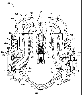
Figure 2 shows a yoke 150 of a pump/motor 190 (the pump/motor
190 is shown in Figures 4-6). As shown in figures 2 and 5A the yoke 150 of
pump/motor 190 includes a back plate 152, arms 154, 155, and trunnions 156,
7
CA 02605407 2007-10-17
WO 2006/115472 PCT/US2005/013532
157. The yoke 150 also includes check valves 160 in the back plate 152, which
will be described in detail hereafter.
As seen in Figure 3A, a cross-section of the back plate 152 is shown,
including details of the check valve 160. An enlarged view of a check valve
160 is
shown in Figure 3B. More particularly, the check valve 160 of this embodiment
includes a threaded insert 162 configured to engage a threaded aperture 164 in
the back plate 152. Seal 166 provides a fluid seal between the insert 162 and
the
back plate 152. Poppet valve 168 is biased in a closed position by spring 170.
The yoke 150 further includes fluid channels 172, 173 located within
.10 the arms 154, 155. It may be seen, in Figure 3A, that there are two fluid
channels
172 within the arm 154, and two fluid channels 173 within the arm 155. The
provision of two fluid channels 172, 173 in each of the arms 154, 155 enhances
the stiffness of the arms 154, 155 as compared with arms having single, larger
fluid channels in each of the arms.
In operation, when pump/motor 190 is coupled to the drive train of a
vehicle, high-pressure fluid is introduced to the yoke via port 175 (see
Figure 2)
and travels up the arm 155 to the back plate 152 via channels 173. The high-
pressure fluid is supplied to the valve plate 178 and to the barrel 158 via
fluid
cavities 177. The yoke 150 is sealed within a casing 192 (see Figure 5A).
Space
within the casing 192 around the yoke 150 may be filled with hydraulic fluid,
and
coupled to a low-pressure fluid source, such as an accumulator, via a high
volume,
low loss fiuid connection such as a large-bore pressure hose (not shown).
While fluid pressure within the cavities 177 is greater than, or equal
to fluid pressure outside of the yoke 150, the poppet 168 of the check valve
160
remains in a closed position. Accordingly, operation in a forward mode is
unaffected by the check valve 160. High-pressure fluid enters the cylinders
180 of
the barrel 158 from the fluid cavities 177, driving pistons (not shown)
downward,
and causing the drive plate (not shown) to rotate, as described with reference
to
the pump/motor 102 of Figure 1. The drive plate is connected to the barrel 158
via
a flexible shaft means (not shown) and rotates the barrel 158 in unison. As
the
8
CA 02605407 2007-10-17
WO 2006/115472 PCT/US2005/013532
barrel 158 continues to rotate, fluid from the cylinders.180 is released into
fluid
cavities 176 at low pressure, whence it is returned to the low-pressure
accumulator, via the channels 172 and the trunnion port 174.
To slow the vehicle, the fluid pressure connections at trunnion ports
175, 174 are reversed, as described in more detail hereafter, such that the
high-
pressure fluid. source, a high-pressure accumulator, for example, is coupled
to
trunnion port 174, while the low-pressure fluid source is coupled to trunnion
port
175. In this configuration, low-pressure fluid is drawn into the cylinders 180
of the
barrel 158 via the fluid cavities 177, and pumped at high pressure from the
cylinders 180 into the fluid cavities 176, and thence to the high-pressure
accumulator via the trunnion port 174.
When the pump/motor is operating in pump mode, as occurs during a
braking operation, fluid pressure within the fluid cavities 177 drops below
the fluid
pressure at the low-pressure accumulator. In known systems, such as that
described with reference to Figure 1, the pump/motor must develop enough
suction to draw fluid through the valves and channels of the pump/motor, as
. previously described, which consumes energy. However, in the embodiment
illustrated in Figure 3, as soon as the pressure within the fluid cavities 177
drops
below the pressure of the fluid within the casing 192 around the yoke 150, the
poppet valve 168 opens, permitting fluid to pass directly from the space
around the
yoke 150 into the fluid cavities 177. In this way, low-pressure fluid is
permitted to
enter the pump/motor directly at the back plate 152, without the need to pass
through the valves and passages of the pump/motor. Accordingly, the pressure
losses previously encountered are substantially eliminated. As previously
explained, the casing is provided with a high-volume, low-loss coupling to the
low-
pressure accumulator, which minimizes pressure losses. Figure 3B shows a
detail
of a check valve 160 similar to that shown in Figure 3A. The check valve 160
of
Figure 3B is shown in an open position, as described above. It may be seen,
with
reference to Figure 3B, that when the poppet 168 is in the open position,
fluid may
pass freely around the poppet and into the fluid cavities 177.
9
CA 02605407 2007-10-17
WO 2006/115472 PCT/US2005/013532
While not shown, it will be understood that if the back plate 152 is
provided with check valves on the opposite side, that is, between the fluid
cavities
176 and the exterior of the yoke 150, regenerative braking may be carried out
while the vehicle is traveling in reverse.
According to an alternate embodiment, the check valves may be
configured to remain open under reverse pressures greater than the pressure
found in the low-pressure side of .the circuit, but to close under pressures
much.
lower than the pressure present in the high-pressure side (spring biased
open). In
this way, low-pressure fluid may flow in either direction through the check
valves,
thus further reducing losses by generally bypassing most of the restrictive
passages between the back plate of the pump/motor and the low-pressure fluid
source, for example on the motor discharge side. On the other hand the valves
will close instantly when high pressure is present in the corresponding fluid
cavity.
High pressure fluid must enter or exit the yoke.
Referring again to Figure 1, it may be seen that in the prior art, fluid
traversing the trunnions 120, 121 must execute several sharp turns in entering
or
leaving the pump/motor 102. For example, fluid entering via trunnion port 135
makes a sharp turn to pass axially through the trunnion 121 and through the
bearing 127, and then another sharp turn to rise into the channel 129 of the
arm
133. The fluid returning from the pump/motor must pass through a similar
series of
turns as it exits the trunnion 120. These sharp turns are due in large measure
to
the need for the trunnions 120, 121 to be of a length sufficient to pass
through the
bearings 126, 127, and to mate with fluid ports 136, 137 on the outside of the
pump/motor casing 125.
Figure 4 shows the pump/motor 190 according to an embodiment of
the invention. Figure 5A shows a cross-section of the pump/motor 190 of Figure
4,
taken along line 5-5.
Referring now to Figure 5A, it may be seen that, according to an
embodiment of the invention, in place of full bearings, such as the bearings
126,
127 of Figure 1, partial bearings 196, 197 are shown, which occupy only an
upper
CA 02605407 2007-10-17
WO 2006/115472 PCT/US2005/013532
portion of a region of the respective trunnion 156, 157. While not limiting
the
invention in anyway, applicant believes that in operation, only an upper
portion of a
trunnion bearing is subjected to force of any significance, inasmuch as the
net
effect of all the forces exerted by.the pump/motor is to push the yoke and
trunnion
away from the motor casing in an upward direction, as viewed in Figures 1 or
2.
Consequently, the lower part of the trunnion bearing receives virtually no
force or
pressure.
Trunnion ports 174, 175 are located in positions occupied, in
pump/motors of known art, by the lower portion of the trunnion bearings. For
example, trunnion port 174 is shown exiting trunnion 156 between vertical
planes
that also define the horizontal limits of trunnion bearing 196. Fluid seals
200, 201
are positioned on either side of the trunnion bearings 196, 197 and trunnion
ports
174, 175 of trunnions 156, 157, respectively.
The cross-section of Figure 5A shows the yoke 150 and cylinder
barrel 158 of Figure 2, and provides a cross-sectional view of the trunnions
156,
157. Trunnion ports 174, 175 are shown coupled to fluid ports 182, 183 of the
pump/motor casing 192. It may be seen that the fluid channels 172, 173 are
much
straighter as compared to those of a conventional pump/motor such as
pump/motor 102 of Figure 1, inasmuch as the trunnion ports 174, 175 can now be
positioned in a location that, in the pump/motor of Figure 1, is occupied by
the
lower half of bearings 126, 127. By straightening out the fluid channels 172,
173,
and eliminating the sharp right-angle turns found in the passages 128, 129 of
the
pump/motor 102 of Figure 1, fluid resistance is greatly reduced. This
reduction in
resistance in fluid passages 128, 129 results in a reduced pressure drop
through
these channels, which in turn results in a greater pressure differential
available at
the valve plate of the barrel 158, producing a greater availability of power,
and
improved efficiency of the pump/motor 190.
Additionally, because the trunnion ports 174, 175 are positioned
closer to the center of the pump/motor, the trunnions 156, 157 may be made
shorter than previously known trunnions, such as trunnions 120, 121 of Figure
1,
11
CA 02605407 2007-10-17
WO 2006/115472 PCT/US2005/013532
reducing the size and mass of the. pump/motor 190 as compared to previously
known pump/motors.
Because of the tremendous forces exerted on the trunnions 156, 157
when the pump/motor 190 is in operation, the arms 154, 155 and the trunnions
156, 157 undergo a distortion, with each of the arms 154, 155 tending to pivot
upward and outward on the fulcrums formed by the bearings 196, 197. As a
result,
not only are the forces concentrated on the upper portions of the bearings
196,
197, but the forces are concentrated in a small area of the top of each
bearing
along an inner rim closest to the respective arm 154, 155. According to
various
embodiments of the invention, several bearing configurations are provided to
improve efficiency and reduce wear on the trunnions 156, 157 and bearings
196, 197.
Figures 5B-5D illustrate three of the bearing configurations provided
in accordance with various embodiments of the invention. In each of the
Figures
5B-5D, a sectional detail of the trunnion 157 is shown, together with a
portion of
the pump/motor casing 192 and trunnion end cap 205. It will be understood
that,
while trunnion bearings configured to operate with trunnion 157 are shown,
corresponding bearings are also provided to operate with trunnion 156, which
are
substantially identical, and so need not be illustrated separately.
Figure 5B shows trunnion bearing 197. Bearing 197 is a roller
bearing comprising a cage frame 203 and a plurality of needle rollers 215.
Figure 5C shows a conical bushing 207. Bushing 207 is in the form
of a section of a hollow cone. The bushing 207 tapers in thickness from an
outboard edge 211 to an inboard edge 213, as may be seen by phantom lines T,
which indicate the tapering thickness of the bushing 207. In operation, the
bushing
207 is positioned on the trunnion 157 such that the inboard edge 213 is
closest to
the arm 155. Because of the taper of the bushing 207, when the pump 190 is
idle,
the upper surface closest to the inboard edge 213 does not contact the
corresponding inner surface of the pump casing 192. However, when the pump
190 is in operation, the forces within the pump cause the arm 155 to deform
12
CA 02605407 2007-10-17
WO 2006/115472 PCT/US2005/013532
slightly, flexing outward. As a result, the trunnion 157 is biased in a
clockwise
direction, as viewed in Figure 5C, bringing the entire surface of the bushing
207
into contact with the inner surface of the pump casing 192, effectively
distributing
the load across the surface of the bushing 207, thereby reducing localized
wear.
The bushing 207 may be formed of bronze or some other suitable material, and
may be impregnated with a lubricant.
Figure 5D illustrates a cylindrical bushing 209. In addition to having
a cylindrical cross-section in a first axis C, in order to accommodate the
cylindrical
shape of the trunnion 157, bushing 209 also has a cylindrical cross-section in
a
second axis D, as may be clearly seen in the sectional view of Figure 5D. This
shape permits the bushing 209 to adjust slightly within the space provided for
it in
the trunnion 157 of Figure 5D as the varying forces placed on the trunnion 157
cause it to rotate slightly on the second axis D within the pump/motor casing
192.
In this way, the stresses can be evenly distributed across the upper and lower
surfaces of the. bushing 209, preventing localized wear and stress. As with
the
bushing 207 of Figure 5C, the bushing 209 may be formed of bronze or some
other suitable material, and may be impregnated with an appropriate lubricant.
Currently known pump/motors employ couplings and hoses to carry
high- and low-pressure fluid between the pump/motor and control valves located
externally to the pump/motor. As has been previously explained, each time the
fluid in a hydraulic circuit passes through a restriction in the passage or is
required
to make a sharp turn, there is an associated energy cost. Additionally, there
is a
pressure drop associated with any fluid channel. This "line loss" varies in
direct
proportion to the length of the channel.
Figure 6 is a cross-sectional view of the pump/motor 190 taken along
line 6-6 of Figure 4. Referring to Figure 4, a fluid supply channel 198 may be
seen
as it curves up toward the trunnion cover plate 204. The fluid supply channels
198, 199 are integrated into the structure of the pump/motor frame,
eliminating the
need for an external hose in this location. Referring to Figure 6, the fluid
supply
channels 198, 199 may be clearly seen, positioned to carry fluid to and from
the
13
CA 02605407 2007-10-17
WO 2006/115472 PCT/US2005/013532
yoke 150 via spool valve 210. It may be seen, with reference to Figures 4 and
6,
that the fluid supply channels 198, 199 are configured to provide passage for
hydraulic fluid, while avoiding sharp turns and tight restrictions, wherever
possible.
Additionally, a spool valve 210 is integrated into the pump/motor frame.
Because
high- and low-pressure switching is accomplished by the spool valve 210,
couplings and transmission lines between exterior switching valves and the
pump/motor 190 are eliminated. Furthermore, by combining the function of the
two
valves 142, 143 of Figure 1 into a single valve 210 of Figure 6, complexity is
reduced, and durability and safety are improved.
The structure and operation of a spool valve similar to that illustrated
with reference to Figure 6 is described in more detail in U.S.
PatentApplication No.
10/731,985, which is incorporated herein by reference, in its entirety.
Other valves may also be incorporated into the structure of the
pump/motor 190, such as pilot valves, check valves, and actuator valves. For
example, generally referring to Figures 6 and 5A, an actuator 218 controls the
rotation of the yoke 150 on trunnions 156, 157. The actuator 218 is controlled
by
actuator control valve 216, which may be incorporated into the structure of
the
pump/motor 190. A detailed description of the operation of an actuator and
actuator control valve of the type referenced in Figure 6 may be found in U.S.
Patent Application No. 10/767,547, which is incorporated herein by reference,
in its
entirety.
The pump/motor 190 of Figure 6 also includes pressure input ports
212, 214, configured to receive a high-pressure fluid supply and a low-
pressure
fluid supply, respectively.
By incorporating the housings for the associated valves in the body
or casing of the pump/motor, fluid channels formed within the casing can be
routed
directly to the valves with a minimum of obstruction and without passage
through
couplings or hoses. Additionally, because the channels are machined, or
otherwise formed in the steel casing of the pump/motor, they do not have even
the
14
CA 02605407 2007-10-17
WO 2006/115472 PCT/US2005/013532
minimal resiliency associated with flexible pressure lines, thereby
eliminating
another source of energy loss.
Channels formed within the pump/motor casing are almost always
shorter than equivalent channels formed using hoses, since a hose channel is
required to follow a longer path around the pump/motor. The pressure loss is
reduced over known systems and, additionally, the number of components of the
pump/motor is reduced. It is known that, in hydraulic systems in general,
hoses
and hose connections are among the most frequent sources of failure and down
time. Thus, by eliminating such from the system, the overall durability and
dependability of the system is improved.
In known systems, such as that previously described with reference
to Figure 1, a first valve 142 is used to couple the fluid supply line 144
alternately
to the high- or low-pressure fluid source, while a second valve 143 is used to
perform the same function for the fluid supply line 145. Such an arrangement
required that the valves 142, 143 be carefully coordinated in their operation.
Otherwise, while reversing the sources of each of the valves 143, 145, there
is a
potential for a period during which both fluid supply lines 144, 145 may be.
connected to the high-pressure source 140 or to the low-pressure fluid source
138,
simultaneously. While such a configuration does not damage the pump/motor 102,
there is no energy transfer during this period. Thus, if a rapid switch is
required,
undesirable delays may occur. Additionally, high-pressure fluid on both sides
of
the pump/motor 102 results in unnecessary drag and wear on the motor.
By incorporating the. valves into a single valve with multiple ports
configured to control a coupling of both fluid supply lines with both the high-
and
low-pressure fluid sources, such as through spool valve 210 of Figure 6, the
coordination of the switching is improved, while the circuitry required to
control the
switching is simplified. If pressure losses in the high- or low-pressure sides
of the
hydraulic circuit of the pump/motor are reduced, the pressure differential at
the
valve plate of the pump/motor will be closer to that between the high- and low-
CA 02605407 2007-10-17
WO 2006/115472 PCT/US2005/013532
pressure fluid sources. This will result in an increase in available power as
well as
improved fuel economy for an associated vehicle.
Additionally, if losses on the low-pressure side of the pump/motor
circuit are reduced through the employment of one or more of the improvements
described herein, the maximum pressure required in the low-pressure side of
the
circuit to overcome those losses may also be reduced. This makes possible the
reduction of the overall pressure in the low-pressure accumulator, resulting
in a
further increase in the pressure differential at the motor, with a concomitant
increase in available power to the motor.
Finally, if the maximum pressure in the low-pressure side of the
circuit is reduced, the pressure within the pump/motor casing will also be
reduced.
With lower pressure in the pump/motor casing, the casing may be manufactured
to
lower pressure tolerances. Additionally, the low-pressure accumulator may also
be manufactured to lower pressure tolerances. This allows a reduction in mass
and weight of the casing and accumulator, which further increases the
operational
economy of the pump/motor while reducing its overall size, without reducing
its
power output.
All of the above U.S. patents, U.S. patent application publications,
U.S. patent applications, foreign patents, foreign patent applications and non-
patent publications referred to in this specification and/or.listed in the
Application
Data Sheet, are incorporated herein by reference, in their entirety.
From the foregoing it will be appreciated that, although specific
embodiments of the invention have been described herein for purposes of
illustration, various modifications may be made without deviating from the
spirit
and scope of the invention. Accordingly, the invention is not limited except
as by
the appended claims.
16