Sélection de la langue

Search

Sommaire du brevet 2606788 

Énoncé de désistement de responsabilité concernant l'information provenant de tiers

Une partie des informations de ce site Web a été fournie par des sources externes. Le gouvernement du Canada n'assume aucune responsabilité concernant la précision, l'actualité ou la fiabilité des informations fournies par les sources externes. Les utilisateurs qui désirent employer cette information devraient consulter directement la source des informations. Le contenu fourni par les sources externes n'est pas assujetti aux exigences sur les langues officielles, la protection des renseignements personnels et l'accessibilité.

Disponibilité de l'Abrégé et des Revendications

L'apparition de différences dans le texte et l'image des Revendications et de l'Abrégé dépend du moment auquel le document est publié. Les textes des Revendications et de l'Abrégé sont affichés :

  • lorsque la demande peut être examinée par le public;
  • lorsque le brevet est émis (délivrance).
(12) Brevet: (11) CA 2606788
(54) Titre français: DISPOSITIF A PERCUSSION POUR PERFORATRICE DE ROCHES, PROCEDE POUR OBTENIR UN MOUVEMENT DE PISTON ALTERNATIF A PERCUSSION ET PERFORATRICE DE ROCHES
(54) Titre anglais: PERCUSSION DEVICE FOR A ROCK DRILLING MACHINE, METHOD FOR ACHIEVING A RECIPROCATING PERCUSSION PISTON MOVEMENT AND ROCK DRILLING MACHINE
Statut: Périmé et au-delà du délai pour l’annulation
Données bibliographiques
(51) Classification internationale des brevets (CIB):
  • B25D 09/26 (2006.01)
  • B25D 09/16 (2006.01)
  • E21B 01/24 (2006.01)
  • E21B 01/26 (2006.01)
(72) Inventeurs :
  • ANDERSSON, KURT (Suède)
(73) Titulaires :
  • ATLAS COPCO ROCK DRILLS AB
(71) Demandeurs :
  • ATLAS COPCO ROCK DRILLS AB (Suède)
(74) Agent: SMART & BIGGAR LP
(74) Co-agent:
(45) Délivré: 2013-12-24
(86) Date de dépôt PCT: 2006-06-14
(87) Mise à la disponibilité du public: 2006-12-28
Requête d'examen: 2011-05-12
Licence disponible: S.O.
Cédé au domaine public: S.O.
(25) Langue des documents déposés: Anglais

Traité de coopération en matière de brevets (PCT): Oui
(86) Numéro de la demande PCT: PCT/SE2006/000706
(87) Numéro de publication internationale PCT: SE2006000706
(85) Entrée nationale: 2007-10-29

(30) Données de priorité de la demande:
Numéro de la demande Pays / territoire Date
0501448-5 (Suède) 2005-06-22

Abrégés

Abrégé français

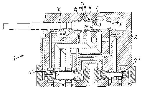
Dispositif à percussion (1) doté d~un piston à percussion alternative (3), comprenant une première chambre (5) qui peut être pressurisée pour l~avance du piston à percussion (3) et une seconde chambre (8) qui peut être pressurisée périodiquement pour le recul du piston à percussion (3). Le dispositif à percussion comprend au moins un piston d~entraînement (7) arrangé pour actionner le recul du piston à percussion (3), une partie dudit piston d~entraînement (7) étant arrangée pour pénétrer dans la seconde chambre (8) pour la commande de la pression sur une surface d~entraînement du piston d~entraînement par la présence d~une moyenne pression dans cette chambre dans le sens du rappel en arrière, le piston d~entraînement (7) comprenant des moyens de coopération en recul avec le piston à percussion (3) et le piston d~entraînement (7) étant exempt de mouvement axial par rapport au piston à percussion (3), dans la direction opposée au recul. L~invention a également pour objet une méthode et une perforatrice de roches.


Abrégé anglais


A percussion device (1) with a reciprocating percussion piston (3) , includes
a first chamber (5) that can be pressurized for forward driving of the
percussion piston (3) and a second chamber (8) that can be periodically
pressurized for back- driving of the percussion piston (3) . The percussion
device includes at least one driving piston (7) arranged for actuating the
back-driving of the percussion piston (3) wherein a portion of said driving
piston (7) is arranged to enter into the second chamber (8) for pressure
actuating on a driving surface of the driving piston by pressure medium being
present in this chamber in the direction of back-driving, wherein the driving
piston (7) includes means for back-driving co- operation with the percussion
piston (3) , and wherein the driving piston (7) is free for axial movement
with respect to the percussion piston (3), opposite the direction of back-
driving. The invention also concerns a method and a rock drilling machine .

Revendications

Note : Les revendications sont présentées dans la langue officielle dans laquelle elles ont été soumises.


8
CLAIMS:
1. Percussion device for a rock drilling machine
including a housing with a reciprocating percussion piston, the
movement of which being controlled by a valve device, wherein
the housing includes a first chamber that can be pressurized
for forward driving of the percussion piston and a second
chamber that can be periodically pressurized for back-driving
of the percussion piston, wherein at least one driving piston
arranged for actuating the back-driving of the percussion
piston is arranged by the percussion piston, wherein a portion
of said driving piston is arranged to enter into the second
chamber for pressure actuating on a driving surface of the
driving piston by pressure medium being present in this chamber
in the direction of back-driving, wherein said driving piston
includes an engagement surface for back-driving co-operation
with an actuating surface on the percussion piston, wherein
said driving piston is free for axial movement with respect to
the percussion piston, opposite the direction of back-driving,
from a position of engagement between the engagement surface
and the actuating surface, and wherein - that said driving
piston includes a cushioning portion for co-operation with a
cushioning chamber in the housing after a performed impact by
the percussion piston, wherein
- the percussion piston is surrounded by the driving piston at
a distance from the first chamber, and
- the cushioning chamber is connected to a pressure medium
source for regaining energy emitted during cushioning.

9
2. Percussion device according to claim 1, wherein the
driving piston is sleeve-shaped and arranged co-axially with
and on the outside of the percussion piston.
3. Percussion device according to claim 1 or 2, wherein
said engagement surface and actuating surface include
ring-shaped surfaces.
4. Percussion device according to claim 1 or 3 and in
dependence of claim 2, wherein the driving piston has a
diameter which exceeds the diameter of the percussion piston.
5. Percussion device according to any one of claims 1-4,
wherein the first chamber is constructed to be pressurized to
an essentially constant pressure.
6. Percussion device according to any one of claims 1-4,
wherein the first chamber is arranged for obtaining a
considerable pressure increase during the back driving of the
percussion piston.
7. Percussion device according to any one of claims 1-6,
wherein a pressure medium conduit is drawn to the first chamber
for maintaining a desired pressure.
8. Percussion device according to any one of claims 1-7,
wherein the second chamber can be periodically pressurized
through a valve device.
9. Percussion device according to any one of claims 1-8,
wherein the first chamber is arranged to receive a rear end of
the percussion piston, as seen in an impact direction against a
tool.

10
10. Method for obtaining a reciprocating percussion
piston movement, wherein a first chamber is pressurized for
forward driving of a percussion piston and a second chamber is
periodically pressurized for back-driving of the percussion
piston, wherein the percussion piston is back-driven by means
of at least one driving piston which is arranged at the
percussion piston, wherein pressure medium in the second
chamber is brought to pressure actuate the driving piston in
the back-driving direction, wherein the driving piston during
back-driving establishes a back-driving co-operation with the
percussion piston, and wherein the driving piston moves axially
freely with respect to the percussion piston, opposite to the
direction of back-driving, from a position of said back-driving
co-operation, and wherein said driving piston by means of a
cushioning portion co-operates with a cushioning chamber in the
housing after a performed impact by the percussion piston,
wherein
- the driving piston during back-driving establishes a
back-driving co-operation with the percussion piston at a
distance from the first chamber, and
- energy emitted during cushioning the cushioning chamber is
regained in a pressure medium source.
11. Method according to claim 10, wherein the first
chamber receives a considerable pressure increase during the
back-driving of the percussion piston.
12. Rock drilling machine including a percussion device
according to any one of claims 1-9.

Description

Note : Les descriptions sont présentées dans la langue officielle dans laquelle elles ont été soumises.


CA 02606788 2012-12-21
24280-90'
=
= 1
PERCUSSION DEVICE FOR A ROCK DRILLING MACHINE, METHOD FOR ,
ACHIEVING A RECIPROCATING PERCUSSION PISTON MOVEMENT AND ROCK
DRILLING MACHINE.
Field of the invention
The invention concerns a percussion device for a rock drilling
machine and a method for
achieving a reciprocating percussion piston movement.
The invention also concerns a
rock' drilling machine including such a percussion device.
Background of the invention =
From US 5,372,196 is previously known a percussion device of
this kind. This percussion device includes a percussion
piston, which is reciprocatingly movable inside a machine
housing. The reciprocating movement of the percussion piston
is controlled by a valve device, wherein the valve element is
movable, to and fro in the machine housing. At its rear end,
the machine housing has a space which is supplied with
pressure fluid and thus drives the percussion piston in the
forward direction. A second chamber that can be pressurized is
arranged for back-driving the percussion piston.
The known percussion device functions well and aims to
obtain percussive frequencies in the magnitude of 150 Hz.
Recently raised desires of higher work rate and better economy
in rock drilling have, however, resulted in the desire for yet
=
higher percussive frequencies.
Features of some embodiments of the invention
Some embodiments
of the present invention may provide a development of a
percussion device as initially defined that gives the
possibility of operation at higher frequency.
=

CA 02606788 2012-12-21
=
24280-90
2
Some embodiments disclosed herein relate to
percussion device for a rock drilling machine including a
housing with a reciprocating percussion piston, the movement of
which being controlled by a valve device, wherein the housing
includes a first chamber that can be pressurized for forward
driving of the percussion piston and a second chamber that can
be periodically pressurized for back-driving of the percussion
piston, wherein at least one driving piston arranged for
actuating the back-driving of the percussion piston is arranged
by the percussion piston, wherein a portion of said driving
piston is arranged to enter into the second chamber for
pressure actuating on a driving surface of the driving piston
by pressure medium being present in this chamber in the
direction of back-driving, wherein said driving piston includes
an engagement surface for back-driving co-operation with an
actuating surface on the percussion piston, wherein said
driving piston is free for axial movement with respect to the
percussion piston, opposite the direction of back-driving, from
a position of engagement between the engagement surface and the
actuating surface, and wherein - that said driving piston
includes a cushioning portion for co-operation with a
cushioning chamber in the housing after a performed impact by
the percussion piston, wherein the percussion piston is
surrounded by the driving piston at a distance from the first
chamber, and the cushioning chamber is connected to a pressure
medium source for regaining energy emitted during cushioning.
Some embodiments disclosed herein relate to method
for obtaining a reciprocating percussion piston movement,
wherein a first chamber is pressurized for forward driving of a

CA 02606788 2012-12-21
24280-90
2a
percussion piston and a second chamber is periodically
pressurized for back-driving of the percussion piston, wherein
the percussion piston is back-driven by means of at least one
driving piston which is arranged at the percussion piston,
wherein pressure medium in the second chamber is brought to
pressure actuate the driving piston in the back-driving
direction, wherein the driving piston during back-driving
establishes a back-driving co-operation with the percussion
piston, and wherein the driving piston moves axially freely
with respect to the percussion piston, opposite to the
direction of back-driving, from a position of said back-driving
co-operation, and wherein said driving piston by means of a
cushioning portion co-operates with a cushioning chamber in the
housing after a performed impact by the percussion piston,
wherein the driving piston during back-driving establishes a
back-driving co-operation with the percussion piston at a
distance from the first chamber, and energy emitted during
cushioning the cushioning chamber is regained in a pressure
medium source.
By providing a driving piston, having a driving area
for actuation by pressure fluid in the second chamber, that can
be made as great as desired, and in particular greater than a
corresponding actuating surface on the percussion piston
itself, the possibility is provided for increased back-driving
speed and thereby increased percussion frequency.
Further, by the driving piston being separate, which
in this connection means free for axial movement with respect
of the percussion piston after that the percussion piston has
performed its impact on a drill shank, it is avoided that an

CA 02606788 2012-12-21
24280-90
2b
unfavourably shaped stress wave is produced in the drilling
steel. In particular it is avoided that a stress wave peak is
formed, which could be operationally unfavourable since it
would bring along undesired strain peaks in the drilling steel.
The percussion piston can therefore according to the invention
be constructed optimally for performing the impact itself,
whereas the back-driving aspects are considered when
constructing the driving piston.
A further advantage may be that the pressure in the
second chamber can be chosen lower and that the percussion
device still can have an essentially higher percussive
frequency than a percussion device according to the background
art.
With an arrangement according to the invention it is
fully realistic to reach percussive frequencies of 300-500 Hz.
Also other, particularly higher, percussive frequencies can,
however, exist.

CA 02606788 2007-10-29
WO 2006/137775
PCT/SE2006/000706
3
It is preferred that the driving piston includes a
cushioning portion for co-operation with a cushioning chamber
in the housing after performed impact of the percussion piston
in order to obtain gentle cushioning of the driving piston
after that the driving piston has ceased its co-operation with
the percussion piston. In particular it is preferred that said
cushioning chamber is connected to a pressure medium source
for regaining energy emitted during cushioning by the
increased pressure in the cushioning chamber being transmitted
to said pressure medium source.
It is preferred that the first chamber is arranged to be
pressurized to a permanent pressure. In particular the second
chamber is periodically pressurized through the valve device.
Through the arrangement with the driving piston, the relation
between the driving area, pressure in the second chamber and
pressure in the first chamber, can be chosen optimally in
order to obtain a desired percussive frequency.
Corresponding advantages are obtained in a method and a
rock drilling machine according to the invention.
Brief description of drawings
The invention will now be described in more detail by way of
embodiments and with reference to the annexed drawings,
wherein:
Fig. 1 diagrammatically shows a percussion device
according to the invention with the percussion piston in a
first position,
Fig. 2 shows the percussion device in Fig. 1 with
the percussion piston in a second position, and
Fig. 3 diagrammatically illustrates a method
according to the invention by means of a block diagram.
Description of embodiments

CA 02606788 2007-10-29
WO 2006/137775
PCT/SE2006/000706
4
A percussion piston 1 shown in Fig. 1 includes, inside a
housing 2, a reciprocatingly movable percussion piston 3 which
with a rear pressure surface 6 is actuated by the pressure of
pressurized fluid in a first chamber 5 in a forward direction
of the percussion piston 3 for acceleration before performing
an impact against a tool (not shown).
At a distance from the first chamber, the percussion
piston 3 is surrounded by a driving piston 7, which with a
driving surface including a first driving area 9 and a second
driving area 10 is actuated by the pressure of a pressurized
fluid in a second chamber 8 for back-driving the percussion
piston 3 after a performed impact. For that purpose, the
driving piston 7 has a ring-shaped engagement surface 13,
which in a back-driving position co-operates with an actuating
surface 14 on the percussion piston 3 for displacing the
percussion piston 3 in backward direction, to the right as
seen in Fig. 1.
Further, the driving piston 7 includes a cushioning
portion 11, which in an advanced position of the driving
piston 7 enters a cushioning chamber 12 in such a way that
fluid that is enclosed inside this cushioning chamber 2 exerts
a cushioning force on the second driving area 10 of the
driving piston 7.
The first chamber 5 can be permanently pressurized,
whereas the second chamber 8 can be periodically pressurized
over the main valve 4' of the percussion device 1 in such a
way that is per se previously known, whereby the valve element
of the main valve 4' is controlled by the position of the
percussion piston 3, which over a valve portion V on the
percussion piston controls the valve element of the main valve
4' for pressurising and evacuating, respectively, of the
second chamber 8.

CA 02606788 2007-10-29
WO 2006/137775
PCT/SE2006/000706
Fig. 2 shows the percussion device 1 with the percussion
piston 3 in a second position immediately after having
performed an impact against a tool (not shown). In the
position shown in Fig. 2, the driving piston 7 has been
5 displaced so far in the percussion direction that its
engagement surface 13 has left the contact with the actuating
surface 14 of the percussion piston 3. The driving piston 7
has thus no axial contact with the percussion piston 3 in this
position. With its cushioning portion 11 the driving piston 7
now enters the cushioning chamber 12, whereby its kinetic
energy is being regained by the increased pressure of fluid
being present in the cushioning chamber 2 being supplied to a
pressure source over a regain channel 15 and auxiliary valve
4".
By the shown arrangement with a separate driving piston 7
which is free from the percussion piston 3 in connection with
the latter performing its percussion movement, a
disadvantageous stress wave configuration is avoided which
otherwise would occur with a correspondingly added form to a
percussion piston.
The method according to the invention for achieving a
reciprocating percussion piston movement is diagrammatically
illustrated in Fig. 3 as a block sequence.
Position 20 indicates the start of the sequence.
Position 21 indicates pressurising the first chamber 5
for the forward driving of percussion piston 3. This can be
performed by essentially direct connection to a system
pressure. (Mode 1).
Position 22 indicates evacuating pressure fluid in the
second chamber 8 and thereby initiating a percussion movement
of the percussion piston 3.
Position 23 indicated performing the percussion movement.
The driving piston 7 now follows the percussion piston 3 in

CA 02606788 2007-10-29
WO 2006/137775
PCT/SE2006/000706
6
the forward direction until the impact has been completed.
Thereafter the driving piston 7 moves axially freely with
respect of the percussion piston 3 in the percussion
direction.
Position 24 indicates the entering of the driving piston
7 with a cushioning portion 11 into a cushioning chamber 12
for cushioning its axial movement and possibly also for
regaining the kinetic energy of the driving piston 7.
Position 25 indicates the stop of the sequence.
In a modified sequence it is provided that a connection
to the first chamber can be blocked. This way is ensured a
considerable pressure increase in the first chamber during the
back-driving of the percussion piston. This pressure increase
is as an example in the magnitude 3 times the system pressure.
It is thus to be understood that other increase rates can
exist.
The invention can be modified within the scope of the
following claims. The driving piston as well as the percussion
piston can be constructed otherwise with differently formed
mutual means for achieving back-driving connection. In a
modified driving piston, a specific thinned cushioning portion
is missing. The driving piston can thus have unchanged section
along its axial extension. It is also possible to have the
driving piston constructed otherwise than as a sleeve. It can
also be possible to have a plurality of driving pistons with
suitable design distributed around the percussion piston.
The invention makes it possible to provide percussion
devices with slender percussion pistons that are well shaped
for their impact operation and still have powerful means for
effective and fast back-driving of the percussion piston,
whereby the aim of higher percussive frequency can be reached
with relatively simple and cost efficient measures.

CA 02606788 2007-10-29
WO 2006/137775
PCT/SE2006/000706
7
It is not necessary for the invention that the kinetic
energy of the driving piston is regained in the manner that is
described above even if this is preferred, i.a. because it
contributes to better operating economy.
The energy loss occurring because the mass of the driving
piston is not contributing to the impact energy at impact, can
because of this aspect be regained by supplying the increased
pressure in the cushioning chamber directly to the pressure
system. More specifically it is regained through an
accumulator (not shown in the figures) which is connected to
the pressure system. The valve 4" I Figs. 1 and 2 receives in
the shown embodiment a signal from the valve V to open in
order to free the connection between the cushioning chamber 12
and the system.
Other arrangements for obtaining the movement of the
driving piston can also come into question. The valve
arrangement for controlling the reciprocating movement can be
constructed otherwise, for example by initiating a valve
movement in any other way than through a valve portion V on
the percussion piston.

Dessin représentatif
Une figure unique qui représente un dessin illustrant l'invention.
États administratifs

2024-08-01 : Dans le cadre de la transition vers les Brevets de nouvelle génération (BNG), la base de données sur les brevets canadiens (BDBC) contient désormais un Historique d'événement plus détaillé, qui reproduit le Journal des événements de notre nouvelle solution interne.

Veuillez noter que les événements débutant par « Inactive : » se réfèrent à des événements qui ne sont plus utilisés dans notre nouvelle solution interne.

Pour une meilleure compréhension de l'état de la demande ou brevet qui figure sur cette page, la rubrique Mise en garde , et les descriptions de Brevet , Historique d'événement , Taxes périodiques et Historique des paiements devraient être consultées.

Historique d'événement

Description Date
Le délai pour l'annulation est expiré 2016-06-14
Lettre envoyée 2015-06-15
Accordé par délivrance 2013-12-24
Inactive : Page couverture publiée 2013-12-23
Inactive : Taxe finale reçue 2013-10-11
Préoctroi 2013-10-11
Inactive : Lettre officielle 2013-05-14
Lettre envoyée 2013-05-14
Un avis d'acceptation est envoyé 2013-05-14
Inactive : Approuvée aux fins d'acceptation (AFA) 2013-05-01
Modification reçue - modification volontaire 2012-12-21
Inactive : Dem. de l'examinateur par.30(2) Règles 2012-06-21
Lettre envoyée 2011-05-25
Exigences pour une requête d'examen - jugée conforme 2011-05-12
Requête d'examen reçue 2011-05-12
Toutes les exigences pour l'examen - jugée conforme 2011-05-12
Inactive : CIB enlevée 2009-06-15
Inactive : CIB attribuée 2009-06-15
Inactive : CIB en 1re position 2009-06-15
Inactive : CIB attribuée 2009-06-15
Inactive : Page couverture publiée 2008-01-25
Lettre envoyée 2008-01-23
Inactive : Notice - Entrée phase nat. - Pas de RE 2008-01-23
Inactive : CIB en 1re position 2007-11-22
Demande reçue - PCT 2007-11-21
Exigences pour l'entrée dans la phase nationale - jugée conforme 2007-10-29
Demande publiée (accessible au public) 2006-12-28

Historique d'abandonnement

Il n'y a pas d'historique d'abandonnement

Taxes périodiques

Le dernier paiement a été reçu le 2013-05-08

Avis : Si le paiement en totalité n'a pas été reçu au plus tard à la date indiquée, une taxe supplémentaire peut être imposée, soit une des taxes suivantes :

  • taxe de rétablissement ;
  • taxe pour paiement en souffrance ; ou
  • taxe additionnelle pour le renversement d'une péremption réputée.

Les taxes sur les brevets sont ajustées au 1er janvier de chaque année. Les montants ci-dessus sont les montants actuels s'ils sont reçus au plus tard le 31 décembre de l'année en cours.
Veuillez vous référer à la page web des taxes sur les brevets de l'OPIC pour voir tous les montants actuels des taxes.

Historique des taxes

Type de taxes Anniversaire Échéance Date payée
Taxe nationale de base - générale 2007-10-29
Enregistrement d'un document 2007-10-29
TM (demande, 2e anniv.) - générale 02 2008-06-16 2008-05-08
TM (demande, 3e anniv.) - générale 03 2009-06-15 2009-05-12
TM (demande, 4e anniv.) - générale 04 2010-06-14 2010-05-06
TM (demande, 5e anniv.) - générale 05 2011-06-14 2011-05-06
Requête d'examen - générale 2011-05-12
TM (demande, 6e anniv.) - générale 06 2012-06-14 2012-05-09
TM (demande, 7e anniv.) - générale 07 2013-06-14 2013-05-08
Taxe finale - générale 2013-10-11
TM (brevet, 8e anniv.) - générale 2014-06-16 2014-06-09
Titulaires au dossier

Les titulaires actuels et antérieures au dossier sont affichés en ordre alphabétique.

Titulaires actuels au dossier
ATLAS COPCO ROCK DRILLS AB
Titulaires antérieures au dossier
KURT ANDERSSON
Les propriétaires antérieurs qui ne figurent pas dans la liste des « Propriétaires au dossier » apparaîtront dans d'autres documents au dossier.
Documents

Pour visionner les fichiers sélectionnés, entrer le code reCAPTCHA :


Pour visualiser une image, cliquer sur un lien dans la colonne description du document. Pour télécharger l'image (les images), cliquer l'une ou plusieurs cases à cocher dans la première colonne et ensuite cliquer sur le bouton "Télécharger sélection en format PDF (archive Zip)" ou le bouton "Télécharger sélection (en un fichier PDF fusionné)".

Liste des documents de brevet publiés et non publiés sur la BDBC .

Si vous avez des difficultés à accéder au contenu, veuillez communiquer avec le Centre de services à la clientèle au 1-866-997-1936, ou envoyer un courriel au Centre de service à la clientèle de l'OPIC.


Description du
Document 
Date
(aaaa-mm-jj) 
Nombre de pages   Taille de l'image (Ko) 
Description 2007-10-28 7 287
Dessin représentatif 2007-10-28 1 47
Dessins 2007-10-28 2 104
Abrégé 2007-10-28 1 85
Revendications 2007-10-28 4 130
Revendications 2012-12-20 3 113
Description 2012-12-20 9 355
Dessin représentatif 2013-11-24 1 38
Courtoisie - Certificat d'enregistrement (document(s) connexe(s)) 2008-01-22 1 108
Rappel de taxe de maintien due 2008-02-17 1 113
Avis d'entree dans la phase nationale 2008-01-22 1 195
Rappel - requête d'examen 2011-02-14 1 117
Accusé de réception de la requête d'examen 2011-05-24 1 179
Avis du commissaire - Demande jugée acceptable 2013-05-13 1 163
Avis concernant la taxe de maintien 2015-07-26 1 171
PCT 2007-10-28 3 97
Correspondance 2013-05-13 1 33
Correspondance 2013-10-10 2 78