Note : Les descriptions sont présentées dans la langue officielle dans laquelle elles ont été soumises.
CA 02607430 2007-10-23
LUGLESS SCANNER TRANSFER
Field of the Invention
This invention relates to the field of lumber transfers and in particular to a
transfer
for transporting workpieces such as flitches or cants through a scanner
without the use of lugs on
the transfer so as to provide for optimizing the spacing between the
workpieces.
Backuound of the Invention
Ducker scanner transfers are used to pass flitches or cants through a
transverse
scanner in order to optimize them for subsequent processing through an edger
or gangsaw. The
duckers are used to stop pieces in order to correctly sequence them through
the system while the
transfer chains continue to run underneath. As speeds have increased over the
years, problems
have arisen with their operation. Pieces "bounce back" when stopped by a
ducker and the higher
the transfer speed, the worse the problem gets. To overcome this, mechanical
apparatus such as
kick back fingers and anti-kick back saw blades have been used. This adds to
the cost, complexity
and maintenance needs of the system without entirely solving the problem.
An alternative approach is to use lugged transfers. These have fixed lugs on
the
transfer chains. Because they are fixed the lugs need to be spaced apart far
enough to
accommodate the widest piece. This then requires, for maximum throughput, a
variable speed
drive so that when narrow pieces are processed the chain has to run fast to
deliver them in time
and slower for wide pieces. Again, this adds expense and complexity to the
system.
1
CA 02607430 2007-10-23
Summary of the Invention
In summary, the invention overcomes some of the mechanical difficulties,
complexity and expense of the afore-mentioned solutions with a cheaper,
simpler mechanical
solution by using improved logic and controls.
The present invention the transfer does not use lugs or duckers positioning
workpieces in a known location on a scanner transfer without affecting that,
after scanning, the
workpieces are presented to a ninety degree turn into the sawing machine with
the correct spacing
so that pieces are fed to the sawing machine with optimally smallest gaps.
According to a first embodiment of the present invention there is disclosed a
lugless
scanner system for cooperatively feeding elongate workpieces to an edger or
gang saw wherein the
edger or gang saw process the workpieces linearly at a preset constant through-
put speed. The
workpieces are processed sequentially by the edger or gang saw and each
workpiece has a
characteristic length so that for each individual workpiece there is a
corresponding characteristic
processing time and thus a corresponding infeed time required for a trailing
end of each workpiece
to clear through an infeed to the edger or gang saw. The system comprises:
a scanner upstream from the edger or gang saw and the corresponding infeed,
a lugless transfer extending from upstream of the scanner and cooperating with
the
scanner so as to sequentially pass the workpieces through the scanner at a
constant transfer
velocity, and extending downstream from the scanner to the infeed
corresponding to the edger or
gang saw,
at least one sensor at the upstream end of the lugless transfer for sensing a
unique
position of each workpiece on the lugless transfer and the unique length
corresponding to each
workpiece,
2
CA 02607430 2007-10-23
a processor communicating with the at least one sensor, the processor
determining
relative position data between sequential workpieces on the lugless transfer
[according to their
unique position and unique length],
a stop upstream of the upstream end of the lugless transfer cooperating with a
supply of the workpieces supplying the workpieces in a downstream direction to
the stop, the stop
regulating the sequential feeding of single workpieces onto the lugless
transfer according to
instructions from the processor,
the processor causing the stop to regulate the workpieces sequentially onto
the
upstream end of the lugless transfer according to timing instructions
resulting in a desired gap
between sequential workpieces on the lugless transfer,
and wherein the unique gap between adjacent and sequential workpieces on the
lugless transfer corresponds to a clearance time, determined by the processor,
required for the
downstream workpiece to clear its trailing end from the infeed corresponding
to the edger or gang
saw as the leading edge of the upstream workpiece of the adjacent and
sequential workpieces is
delivered on the lugless transfer to the infeed or the edger or gang saw so as
to produce and
optimally minimized gap between sequential workpieces fed into the edger or
gang saw.
According to a further embodiment of the present invention there is disclosed
a
method for transferring a workpiece oriented transversely on a lugless
transfer, transversely
relative to the direction of flow, downstream from an upstream end of the
transfer to an opposite
downstream end. The workpiece is transferred along a flowpath in the direction
of travel
therebetween so as to pass at a constant first velocity the workpiece to,
firstly, a selectively
actuable stop temporarily preventing flow of the workpiece along the flowpath,
and secondly
through a sensing zone of a transverse scanner. The workpiece is also
transferred from the
downstream end of the transfer to an infeed oriented at substantially a right
angle to the flowpath.
3
CA 02607430 2007-10-23
The infeed feeds the workpiece linearly at a constant second velocity into an
edger or gangsaw.
Upstream sensors at the upstream end of the transfer detect the length of the
workpiece, and the
upstream sensors communicate corresponding workpiece length information to a
processor. The
processor is in communication, so as to cooperate with a stop actuator
controlling release of the
workpiece from the stop. The method comprises the steps of:
a) sensing the unique length information of a first workpiece in a
sequentially
presented, substantially parallel array of workpieces at the upstream end of
the
transfer,
b) holding the first workpiece at the stop and releasing the first workpiece
from the
stop upon an actuating trigger signal from the processor,
c) sensing the unique length information of a next upstream second workpiece
which
is next upstream from the first workpiece in the array of workpieces at the
upstream end of the transfer,
d) passing the first workpiece through the sensing zone of the scanner so as
to scan
the first workpiece for optimization of a unique sawing solution in the
process and
so as to determine relative lateral position of the first workpiece in the
transfer, and
passing the first workpiece along the downstream end of the transfer and onto
the
infeed,
e) actuating the stop when the first workpiece is clear of the stop to
temporarily hold
the next upstream second workpiece at the stop for selective release
downstream
along the transfer,
f) determining in the processor the required space on the transfer between the
first
and second workpieces given their respective unique length information and the
4
CA 02607430 2007-10-23
constant velocity of the transfer so as to minimize a gap between a trailing
end of
the first workpiece and a leading end of the second workpiece on the infeed,
g) triggering actuation of the stop upon a triggering signal from the
processor so as to
release the second workpiece from the stop to create the required space
between
the first and second workpieces.
The step of determining the required space on the transfer between the first
and
second workpieces may include the steps of
a) collecting and at least temporarily storing the unique length and lateral
position
information of the first and second workpieces in the processor
b) using the first and second constant velocities, determining any potential
overlap
between the trailing end of the first workpiece and the leading end of the
second
workpiece and the required time, given the second velocity, to reduce the
potential
overlap to zero without thereby creating more than a minimized gap between the
trailing end of the first workpiece and the leading end of the second
workpiece, and
given the first velocity and the required time, determining the required space
on the
transfer between the first and second workpieces to achieve the minimized gap.
Brief Description of the Drawings
Figure 1 is a schematic drawing of the process of the present invention.
Figure 2 is a side elevation view of the system of the present invention.
Figure 3 is a top plan view of one embodiment of the system of the present
invention.
5
CA 02607430 2007-10-23
Detailed Description of Embodiments of the Invention
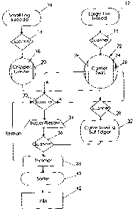
As seen in Figure 1, which is a schematic diagram by way of example of a
process
for converting a small log or a large log into sawn dimensional lumber,
smaller logs are fed to a
small log infeed 10 and larger logs are fed to a large log infeed 12 and
subsequently scanned by
scanners 14 and 16 respectively for entering into their respective canters. In
particular, small logs
are canted in chipper canter 18 so as to produce a cant 20 and the large logs
are canted in the
canter-twin 22 which then produces what are diagrammatically shown as a centre
cant 24 and
sideboards or flitches 26. Cants 20 and 24 are directed through scanner 28 and
flitches 26 are
directed through scanner 30 for, respectively, curve sawing and bull edging of
cants 20 and 24 in
curve sawing gangs 32 and for edging in edger 34. The resulting boards having
been curve sawn
from cants 20 and 24 or edged from flitches 26, are scanned in scanner 36 and
sent to trimmer 38
for trimming and either redirection for remanufacture or for sorting in sorter
40 before drying in
kiln 42.
The present invention deals with the use of lugless transfers transferring
either for
example the flitches 26 through scanner 30 or the cants 20 and 24 through the
scanner 28 for,
respectively, edging in edger 34 or curve sawing in curve sawing gangs 32.
In the example of Figure 2, which illustrates the scanning by scanner 30 of
flitches
26 prior to infeed positioning on a positioning table 44 for positioning of
the flitches for infeed to
edger 34.
Thus flitches 26 flow in direction A from canter-twin 22 to scanner 30 on a
sort
transfer 46 to, in the illustrated example, a pass/turn gate 48. Pass/turn
gate 48 orients flitches 26
so that their wane sides are facing upwards whereupon the lugless scan chains
50 bring the flitches
26 in direction B firstly to one, and in alternative embodiments for example
two duckers 52 from
which flitches 26 are selectively released for transfer on scan chains 50
through scanner 30. Photo
6
CA 02607430 2007-10-23
eyes 54 positioned upstream of duckers 52, are other length sensing devices
such as upstream
scanners or the like, determine the unique length associated with each
individual flitch 26 and
transmit this information to processor 56. Processor 56, which may otherwise
be known as an
optimizer, determines optimum wait times between sequential flitches 26 so as
to minimize a gap
58 between flitches 261eaving the positioning table 44 for infeed in direction
C into edger 34 so as
to thereby maximize through-put through the edger. Thus, between adjacent
flitches 26 flowing in
direction B on scan chains 50, the unique wait time computed by processor 56
for the wait time
between the sequential flitches 26 results in individually computed release
times for releasing the
corresponding flitches 26 from duckers 52 by the communication of a trigger
signal from
processor 56 to the programmable logic controllers (PLCs) (not shown)
controlling the actuation
of duckers 52.
Thus as maybe seen, the present invention does away with the conventional
series
of duckers between the scanner 30 and positioning table 44 or lugs and uses
only smooth transfer
chains 50 to pass workpieces through the scanner 28,30. In order to space the
workpieces
optimally, the workpieces are sequenced from a single ducker 52 spaced some 15
inches from the
pass/turn gate 48. This ducker 52 is used to square up flitches 26 or cants
20,24 and then release
them at the appropriate time to leave an optimized, for example approximate 12
inch, air gap 58
between the trailing edge of a first or downstream piece (see for example
flitch 26') and the leading
edge of a second or upstream piece (see for example flitch 26"). The gapping
is achieved by using
length and/or width photo-eyes to assess the length and/or width of each
piece.
In transverse fed sawing machines such as in the example of Figure 3, one
problem
is the speed at which pieces are moved from a transverse motion to a linear
one and into the
sawing machine. For pieces shorter than about 12feet long, this is not a
problem since the feed
through the sawing machine is faster than the transverse motion to get the
next piece in line. For
longer pieces conventionally the transverse motion has to be paused so that
the leading end of a
second or upstream piece 26" does not hit the trailing end of a first or
downstream piece 26' being
processed in the sawing machine 34.
7
CA 02607430 2007-10-23
The lugless scanner transfer method and apparatus according to the present
invention will solve this problem by one of two means. In the first solution,
pieces will be
transversely moved towards the feed line and the transfer speed ramped up and
down so that
longer pieces will not interfere with preceding pieces, similar to what is
presently done with a
lugged transfer. A limitation of this approach is acceleration and
deceleration rates must be low
enough so that pieces do not slide on the transfer chain. In the second and
more preferred solution,
by using the length information corresponding to each unique workpiece from
the photo-eyes 54, a
variable air gap 58 will be achieved between the longer workpieces which will
equate to the time
required to just miss the end of the preceding downstream piece 26' as it is
fed into the sawing
machine 34. Thus the transfer chains 50 can be run at a fixed speed, which is
advantageous as it is
simpler and less expensive and reduces the risk of pieces sliding.
As will be apparent to those skilled in the art in the light of the foregoing
disclosure, many alterations and modifications are possible in the practice of
this invention
without departing from the spirit or scope thereof.
8