Note : Les descriptions sont présentées dans la langue officielle dans laquelle elles ont été soumises.
CA 02607622 2007-10-24
SEAT FOR ARMORED VEHICLE
SPECIFICATION
FIELD OF THE INVENTION
The present invention relates to a seat for an armored
vehicle. More particularly this invention concerns such a seat
that protects the seat's occupant with respect to land mines.
BACKGROUND OF THE INVENTION
A seat in an armored vehicle typically has a frame
covered with a seat cover and connected to a hanger frame attached
to the vehicle roof. Mounting the seat on the ceiling rather than,
as is standard in most vehicles, on the floor, protects the
occupants in the event of a land-mine explosion underneath the
vehicle, which typically pushes up the floor.
Land mines present a great danger to vehicles and their
crews due to their extremely high destructive force combined with
their frequent occurrence in regions of crisis and war. Since the
probability of running over mines is particularly high in the case
of peacekeeping deployments, very high requirements for protection
are placed even on lightly armored vehicles.
Effective protection for the crew essentially depends on
the design of the seat and its attachment to the armored vehicle.
As mentioned above, attachment of the seats to the floor or to the
vehicle wall is not appropriate for mine protection since in
response to a mine detonation the outer shell of the vehicle
- 1 -
CA 02607622 2007-10-24
facing the detonation, in most cases the vehicle floor and the
lower section of the outer vehicle wall, is accelerated and
dynamically deformed inward so much that the forces transferred to
the occupants are a multiple of the physiologically allowable
acceleration and hence very injurious.
EP 1,382,932 describes a safety system which takes into
account this requisite decoupling of the seats from the vehicle
floor and from the side wall of the vehicle by suspending the seat
from the vehicle roof and strapping it down to the floor. Seats of
this type, however, have the fundamental disadvantage that they
maintain their protection only when the floor structure is not
deformed, that is not shifted upward toward the roof. Due to the
significant dynamic deformation of the floor structure in a mine
detonation, the seat loses its stable anchorage provided by the
floor straps, and thus its rigid shape as well, since the straps
attached to the floor go slack. This loosening of the floor straps
takes away from the safety system the rigid shape required for the
protective function, and the seat system can no longer ensure an
upright seat position required for the protective function in
relation to the direction of acceleration, with the result that in
the worst case the occupants are even accelerated together with
their seat against the vehicle roof, despite the intact restraint
system. Similar safety systems are described in US 3,868,143, in
GB 2,276,080, and in US 2,829,702.
US 2005/0264082 describes an armored vehicle having a
floor, a roof above the floor, and a side wall extending
vertically between the floor and the wall. It is provided with a
seat having a rigid frame, at least one ceiling mount suspending
the frame from the roof, a cover on the frame forming surfaces
adapted to hold a seated occupant, and a harness on the frame
retaining the occupant seated on the cover. The frame and cover
- 2 -
CA 02607622 2007-10-24
are wholly disengaged and disconnected from the floor. The cover
includes an upright back panel engaging a back of the occupant of
the seat, a seat panel engaging underneath and supporting the
occupant of the seat, and a pair of side panels flanking the
occupant of the seat and connected to the back panel and seat
panel. The frame is designed as a rod assembly that can be
completely decoupled from the vehicle floor. The disadvantage of
this arrangement is that it does not allow for any adjustment of
the seat longitudinally or in height, as is required for the
driver and operating personnel in the vehicle so as to be able to
adjust the working position ergonomically to a specific body size,
since the seat is attached in a fixed position within the vehicle.
US 6,805,033 describes a vehicle seat that is integrated
in a fixed rod assembly suspended from the vehicle roof and that
can be slid along this obliquely upwardly extending rod assembly.
The disadvantage of this seat is the adjustment capability only in
the direction of the rod assembly, there being no independent
adjustment possible longitudinally or in height. Another
disadvantage is the rigid seat arrangement on the rod assembly
which in the event of a vertical shock load, triggered for example
by a mine detonation under the vehicle, cannot take up the shock
load due to the lack of an elastic suspension.
In another system the seat is also attached to the
vehicle roof or in the upper side wall region. This seat, like US
2005/0264082, is also not adjustable and additionally does not any
of the shock-absorbing features of US 2005/0264082.
US 4,144,797 discloses a seat for operating a weapons
station. Here the seat is attached to a rotatable device suspended
from the roof, and is slidable vertically along this device. Seats
of this type are not suitable for mine protection purposes because
- 3 -
CA 02607622 2007-10-24
here again no energy-absorbing devices are integrated and no
suitable restraint devices are provided.
OBJECTS OF THE INVENTION
It is therefore an object of the present invention to
provide an improved seat for an armored vehicle.
Another object is the provision of such an improved seat
for an armored vehicle that overcomes the above-given
disadvantages, in particular that eliminates the disadvantages
described in the prior art by means of a further development of
the invention described in US 2005/0264082.
SUMMARY OF THE INVENTION
An armored vehicle having a generally horizontal roof
wall and a generally vertical side wall extending downward from
the roof wall is provided according to the invention with a seat
assembly having a hanger frame fixed to at least one of the walls,
clear of a floor of the vehicle, and having a generally upright
side member. A support frame is shiftable at least vertically on
the hanger frame along the side member. A latch can arrest the
support frame at any of a plurality of vertically offset positions
on the side member. A seat is hinged on the support frame next to
the side member and has a sitting part and a back part
horizontally adjacent the side member. The seat is dimensioned to
hold a person horizontally adjacent the side member, and elastic
straps secured to the support frame and at least partially
suspending the seat. A harness is provided to hold a person in the
seat.
- 4 -
CA 02607622 2007-10-24
Thus the support frame is articulated on the side to a
support frame on which the elastic straps are attached, and this
support frame is connected to a hanger frame attached to the
vehicle roof.
Within the scope of the invention, the hanger frame can
be designed as a the rod hanger assembly or as a partition wall
suspended from the vehicle roof.
To enable height adjustment of the seat, a detent-
lockable sliding guide can be provided in the lateral suspension
device.
To enable longitudinal displacement of the seat, the seat
frame can be connected to the lateral suspension device by means
of another detent-lockable sliding guide.
BRIEF DESCRIPTION OF THE DRAWING
The above and other objects, features, and advantages
will become more readily apparent from the following description,
reference being made to the accompanying drawing in which:
FIG. 1 is a rear perspective view of an armored-vehicle
seat according to the invention;
FIG. 2 is a front perspective view of the FIG. 1 seat;
FIG. 3 is a rear perspective view of another armored-
vehicle seat according to the invention; and
FIG. 4 is a front perspective view of the FIG. 3 seat.
SPECIFIC DESCRIPTION
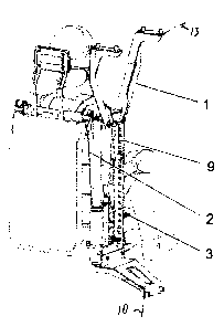
As seen in FIGS. 1 and 2, a rigid hanger frame 1 is
provided that is bolted to the generally horizontal vehicle roof
- 5 -
CA 02607622 2007-10-24
indicated schematically at 13. Connected to the rod hanger frame 1
is a support frame 2 on which a seat 3 is pivotally attached. A
lower portion of the hanger frame 1 can be attached as shown to a
side wall illustrated schematically at 10, which side wall 10 may
itself be suspended from the ceiling. In FIGS. 3 and 4 the hanger
frame 1 is only fixed to the pendant side wall 10. There is no
connection whatsoever to the unillustrated floor of the vehicle
having the roof 13 and side wall 10.
This seat 3 is an open framework made of tubing with a U-
shaped lower part 3' forming a sitting surface and a back part
also made of tubing and hinged at its lower ends about an axis
extending parallel to the vehicle travel direction to the rear
ends of the seat part 3'. This frame 3 is provided with a flexible
seat cover which is composed in particular of two elastic straps
4, a seat surface 5 on the part 3', and a backrest 14. These
components are stitched together. The seat cover is elastic
fabric that may be composed, depending on requirements, of a
fragment-protection fabric, or into which an additional single- or
multilayer fragment-protection material is integrated.
The elastic straps 4 are each attached directly to the
support frame 2, as shown by way of example in FIGS. 1 and 3. More
specifically, each strap 4 is looped over the upper end of the
support frame 2 and is attached somewhat lower down on the support
frame 2 in order to give it maximum length and stretchability,
with the front ends of the straps 4 looped around the side tubes
of the seat frame part 3' so as to elastically support it.
An occupant 6 is held in the seat by a shoulder straps 7
and a lap belt 8.
In order to provide height adjustment of the seat, the
frame 1 has a vertical guide rail 9 formed with a vertical row of
latch holes and cooperating with a pin-type latch (12 in FIG. 4)
- 6 -
CA 02607622 2007-10-24
on the frame 2 carrying the seat 3. A second such guide rail for
the longitudinal displacement of the seat can be provided between
the seat 3 and guide rail 9.
In the embodiment of FIGS. 3 and 4, the guide rail 9' can
be fixed to the side wall 11 that is, as described above,
suspended from the vehicle roof 13. For longitudinal adjustment of
the seat longitudinally, a clamp or detent-type latch is
integrated into the joint between the rail 9' and the seat 3, by
means of which seat 3, and thus the entire seat, can be slid
longitudinally along the rail 9. Since the rail 9' is not vertical
but extends both vertically and somewhat horizontally, simple
movement of the frame 2 along the angled rail 9' provides both
vertical and horizontal (longitudinal) adjustment of the position
of the seat 3 carried on the frame 2. Thus with this embodiment,
it is possible to independently adjust both the height and
longitudinal position of the seat 3.
The lower end of the vertically movable support frame 2
has a lower portion forming a horizontally extending table on
which the seat frame 3 is shiftable and adjustable horizontally in
the travel direction of the vehicle, here parallel to the side
wall 10. This way the person sitting in the seat frame 3 has some
front-to-back adjustability of his mine-protected seat.
In response to a mine detonation under the vehicle,
occupants 6 are pressed into the ergonomically shaped seat cover
on seat 3, which cover, due to the elastic material of straps 4,
reduces the acceleration force acting on occupants 6. In the
opposite direction, occupants 6 are restrained by belts 7 and 8.
- 7 -