Note : Les descriptions sont présentées dans la langue officielle dans laquelle elles ont été soumises.
CA 02607653 2007-10-19
TITLE
Modular scanner assembly
FIELD
The present invention relates to a modular scanner assembly.
BACKGROUND
There are many situations where defects in materials and/or the welds of the
materials must be detected to ensure quality control. The defects may be
internal flaws
such as cracks, voids, etc. produced during the manufacturing of the material,
flaws in the
area of a weld due to inadequate welding preparation and/or practice, or
surface
irregularities due to, in most cases, corrosion.
A preferred method for detecting these flaws is called non-destructive
testing, or
inspection. In non-destructive testing, flaws are detected by various types of
sensors, or
probes, which are translated over the material's surface in a controlled
manner, collecting
data along the way.
SUMMARY
There is provided a modular scanner assembly. The modular scanner assembly
comprises a probe holder support constructed from interconnected
reconfigurable
members. At least one of the interconnected reconfigurable members has a probe
holder.
The probe holder support has wheels attached to at least one interconnected
reconfigurable member for moving the probe holder support across a surface to
be
scanned.
BRIEF DESCRIPTION OF THE DRAWINGS
These and other features will become more apparent from the following
description
in which reference is made to the appended drawings, the drawings are for the
purpose of
illustration only and are not intended to be in any way limiting, wherein:
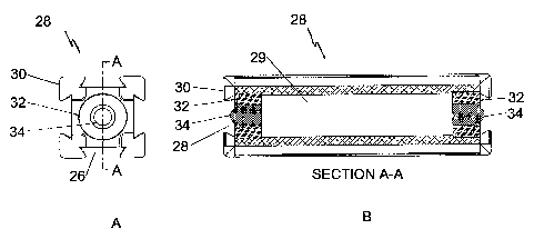
FIG. 1A is an end elevation view of a bar assembly.
CA 02607653 2007-10-19
2
FIG. 1B is a side elevation view in section of the bar assembly along the line
A-A
shown in FIG.1B.
FIG. 2A is a perspective view of a connector block and removable knob
assembly.
FIG. 2B is a side elevation view of the connector block and removable knob
assembly.
FIG. 2C is a rear elevation view in section of the connector block and
removable
know assembly along the line A-A shown in FIG. 2B.
FIG. 3A is a perspective view of a cross block assembly.
FIG. 3B is a front elevation view of the cross block assembly.
FIG. 3C is a side elevation view in section of the cross block assembly along
the
line A-A shown in FIG. 3B.
FIG. 4A is a perspective view of a pivot assembly.
FIG. 4B is a front elevation view of the pivot assembly.
FIG. 4C is a side elevation view in section of the pivot assembly along the
line A-A
shown in FIG. 4B.
FIG. 4D is a side elevation view in section of the pivot assembly along the
line B-B
shown in FIG. 4B.
FIG. 4E is a bottom plan view of the pivot assembly.
FIG. 5A is a perspective view of a first end of a swivel assembly.
FIG. 5B is a perspective view of a second end of the swivel assembly.
FIG. 5C is a top plan view of the swivel assembly.
FIG. 5D is an end elevation view of the swivel assembly.
FIG. 5E is a side elevation view of the swivel assembly.
FIG. 5F is a diagonal view in section of the swivel assembly along the line B-
B
shown in FIG. 5D.
FIG. 5G is a side elevation view in section of the swivel assembly along the
line A-
A shown in FIG. 5C.
FIG. 6A is a perspective view of a wheel block assembly.
FIG. 6B is a top plan view of the wheel block assembly.
FIG. 6C is a side elevation view of the wheel block assembly.
CA 02607653 2007-10-19
3
FIG. 6D is a top plan view in section of the wheel block assembly along the
line B-
B shown in FIG. 6C.
FIG. 7A is a perspective view of an encoded wheel block assembly.
FIG. 7B is a top plan view of the encoded wheel block assembly.
FIG. 7C is a side elevation view of the encoded wheel block assembly.
FIG. 7D is a top plan view in section of the encoded wheel block assembly
along
the line B-B shown in FIG. 7C.
FIG. 8A is a perspective view of a probe holder assembly.
FIG. 8B is a top plan view of the probe holder assembly.
FIG. 8C is an end elevation view of the probe holder assembly pivoting about a
first
pivot axis.
FIG. 8D is a side elevation view of the probe holder assembly.
FIG. 8E is a side elevation view of the probe holder assembly pivoting about a
second pivot axis.
FIG. 8F is a side elevation view of the probe holder assembly pivoting about a
third
pivot axis.
FIG. 8G is bottom plan view in section of the probe holder assembly along the
line
B-B shown in FIG. 8D.
FIG. 9A is a perspective view of a probe clamp assembly.
FIG. 9B is a first side elevation view of the probe clamp assembly.
FIG. 9C is a second side elevation view of the probe clamp assembly.
FIG. 9D is a top plan view of the probe clamp assembly.
FIG. 9E is an end elevation view in section of the probe clatnp assembly along
the
line A-A shown in FIG. 9D.
FIG. 9F is a bottom plan view of the probe clamp assembly.
FIG. 9G is an end elevation view in section of a portion of the probe clamp
assembly along the line C-C shown in FIG. 9F.
FIG.10A is a perspective view of the front end of a probe pivot assembly.
FIG. lOB is a perspective view of the rear end of the probe pivot assembly.
FIG.10C is a front elevation view of the probe pivot assembly.
CA 02607653 2007-10-19
4
FIG. 10D is a side elevation view in section of the probe pivot assembly along
the
line A-A shown in FIG. 10C.
FIG.10E is a top plan view of the probe pivot assembly.
FIG. 10F is a side elevation view in section of a spring strut of the probe
pivot
assembly along the line B-B shown in FIG.10E.
FIG. lOG is a side elevation view of the probe pivot assembly.
FIG. 1 1A is a perspective view of a wheel base assembly with the cover
removed.
FIG.11B is a side elevation view of the wheel base assembly.
FIG.11C is a bottom plan view in section of the wheel base assembly along the
line
B-B shown in FIG. 11B.
FIG. 11D is a detailed bottom plan view of an axle/wheel assembly of the wheel
base assembly.
FIG. 12A is a perspective view of an umbilical assembly.
FIG. 12B is an end elevation view of the umbilical assembly.
FIG. 12C is a side elevation view of the umbilical assembly.
FIG. 12D is an end elevation view of the umbilical assembly with a handle
installed.
FIG. 12E is a side elevation view in section of the umbilical assembly with
the
handle installed along the lines D-D shown in FIG. 12D.
FIG. 13A is a perspective view of an arm assembly.
FIG. 13B is a side elevation view of the arm assembly.
FIG. 13C is a top plan view in section of the arm assembly along the line B-B
shown in FIG. 13B.
FIG. 14A is a perspective view of a swing arm probe holder.
FIG. 14B is a top plan view of the swing arm probe holder.
FIG. 14C is a side elevation view in section of the swing arm probe holder
along the
line A-A shown in FIG. 14B.
FIG. 14D is a side elevation view in section of the swing arm probe holder
along the
line B-B shown in FIG. 14B.
FIG. 14E is a side elevation view in section of the swing arm probe holder
along the
line C-C shown in FIG. 14B.
CA 02607653 2007-10-19
FIG. 14F is a front elevation view of the swing arm probe holder pivoting
about the
first axis.
FIG. 14G is a top plan view of the swing arm probe holder with an alternative
probe
holding means.
5 FIG.15A is a perspective view of a virtual pivot probe holder.
FIG. 15B is a top plan view of the virtual pivot probe holder.
FIG. 15C is a side elevation view of the virtual pivot probe holder.
FIG. 15D is a bottom plan view of the virtual pivot probe holder viewed along
the
line C-C shown in FIG. 15C.
FIG. 15E is a front elevation view in section of the virtual pivot probe
holder along
the line B-B shown in FIG. 15C.
FIG. 16A is a perspective view of a lateral probe positioner assembly mounted
on a
bar.
FIG. 16B is a top plan view of the lateral probe positioner assembly.
FIG. 16C is a bottom plan view of the lateral probe positioner assembly
mounted on
the bar.
FIG. 16D is a side elevation view in section of the lateral probe positioner
assembly
along the line A-A shown in FIG. 16C.
FIG. 16E is an end elevation view in section of the lateral probe positioner
assembly
along the line B-B shown in FIG. 16C.
FIG. 16F is an end elevation view in section of the lateral probe positioner
assembly
along the line C-C shown in FIG. 16C.
FIG. 16G is a perspective view of a slide assembly of the lateral probe
positioner
assembly.
FIG. 17A is a top plan view of a sectional frame assembly.
FIG. 17B is a detailed end elevation view in section of a wheel block assembly
of
the sectional frame assembly along the line A-A shown in FIG. 17A.
FIG. 17C is a detailed end elevation view in section of a side member/bar
connection of the sectional frame assembly along the line B-B shown in FIG.
17A.
FIG. 17D is a perspective view of the sectional frame assembly with the side
members positioned on each end of the bars.
CA 02607653 2007-10-19
6
FIG. 17E is a perspective view of the sectional frame assembly with the side
members positioned closer together.
FIG. 17F is side elevation view of the sectional frame assembly curved to
match
the curve of a surface.
FIG. 18A is a side elevation view of a chain scanner.
FIG. 18B is a perspective view of the chain scanner.
FIG. 18C is a detailed view in section of a buckle assembly used to clamp the
chain
scanner onto a surface.
FIG. 19A is a perspective view of an example of a simplified scanner assembly.
FIG. 19B is a top plan view of the example of a simplified scanner assembly.
FIG. 19C is a front elevation view of the example of a simplified scanner
assembly.
FIG. 19D is a side elevation view of the example of a simplified scanner
assembly.
FIG. 20 is a perspective view of an example of a more complex scanner
assembly.
FIG. 21 is a perspective view of a scanner assembly constructed using the
sectional
frame assembly.
FIG. 22 is an example of a scanner assembly structured using the chain
scanner.
DETAILED DESCRIPTION
A modular scanner assembly may be made up of different interconnected
reconfigurable members to form a probe holder support. The interconnected
reconfigurable members described below, also referred to as modules or
assemblies,
include: a bar assembly, a removable knob assembly, a connector block
assembly, a
cross block assembly, a pivot assembly, a swivel assembly, a wheel block
assembly, a
wheel assembly, an encoded wheel block assembly, a probe holder assembly, a
probe
clamp assembly, a probe pivot assembly, a swing arm probe holder, a virtual
pivot probe
holder, a wheel base assembly, an umbilical assembly, an ergonomic handle, an
arm
assembly, a lateral probe positioner assembly, a sectional frame assembly, and
a chain
scanner assembly.
The assemblies described below may in turn be made up of interconnected
reconfigurable members. It will be understood that the description below are
some
CA 02607653 2007-10-19
7
examples of members that may be used to form a probe holder support, and that
other
assemblies may be provided than those described herein, or the assemblies
described may
be modified, depending on the desired use.
A description of the various interconnected reconfigurable members, or
assemblies, that may be used to construct a scanner assembly will be given
with reference
to FIG. 1 through 18C. Examples of scanner assemblies that may be constructed
using
these assemblies will then be given with reference to FIG.19A through 22.
The Bar Assemblv
Referring to FIG. 1A, a bar assembly, generally identified by reference
numeral
28 includes a bar 30 of square cross section with a dovetail groove 26 down
each of the
four sides. Referring to FIG. 1B, a pair of perpendicular dovetail grooves 28
are also in
both ends of the bar 30, thus totaling 8 dovetail grooves on the bar 30. The
dovetail
grooves 26 and 28 are arranged in this manner such that a male dovetail part
from a
different module can be attached either horizontally or vertically in either
end of the bar
30, as well as anywhere down its length, on any side.
A bushing 32 adapts the large through hole 29 in bar 30 to the spring loaded
ball
plunger 34. The through hole in bar 30 is for weight reduction. The ball
plunger 34 and
bushing 32 are typical in both ends of the bar 30. The purpose of the ball
plunger 34 is to
align any mating male dovetail part with the bar 30 prior to clamping the male
dovetail
part in place. While not shown, the male dovetail part would have an
appropriate detent
for the ball plunger 34 to register in.
To increase the flexibility of any given system, various lengths of bar
assemblies
may be provided.
The Removable Knob assemblv
Referring to FIG. 2C, a removable knob assembly, generally indicated by
reference numera138, is shown. As will be seen below, the removable knob
assembly 38
is used in many of the interlocking components to tighten and loosen them.
Situations
may arise where two or more knobs interfere with each other, thus restricting
the overall
CA 02607653 2007-10-19
8
usability of the system. Finger knob 42, shaft 40, and spring clip 44 make up
a
removable knob assembly which is removed by hand simply by pulling it out of
the
mating socket 48. The finger knob 42 is permanently assembled by means of
adhesive to
the shaft 40. The shaft 40 contains a series of drive lobes, or spline 47,
that engage with
the socket 48 to transmit torque from the finger knob to the socket. A spring
clip 44
retains the knob assembly 38 in the socket 48. The removable knob assembly 38
and
socket 48 are used in a number of assemblies throughout the invention.
The Connector Block assembly
Referring to FIG. 2A through 2C, the connector block assembly is identified
generally by reference numeral 36. The connector block assembly 36 is a
component
used for rigidly connecting two components together that have dovetail
grooves. It is
designed such that when used to connect to two bar assemblies 28 together in
line (end to
end), three of the four sides of the resultant assembly form continuous
dovetail grooves.
The fourth side is obstructed by the socket 48 of the connector block assembly
36.
Specifically, referring to FIG. 2C, the connector block assembly 36 has of a
removable knob assembly 38, a socket 48, a nut 50, an upper block 46, and a
lower block
52. The upper block 46 and lower block 52 together form a square cross section
with 3
of the 4 sides containing dovetail grooves 26, the fourth side reserved for
the socket 48
and the removable knob assembly 38. Referring to FIG. 2B, the upper block 46
and
lower block 52 together also form a male dovetail 27 on both ends of the
connector block
assembly 36. Referring to FIG. 2C, when the removable knob assembly 38 is
rotated in
a clockwise direction, the socket 48 is threaded into the upper block 46 thus
causing the
small shoulder on socket 48 to push on the lower block 52. Referring to FIG.
2B, the
resulting separating force between the upper block 46 and lower block 52
allows the
connector block assembly 36 to be used to connect two components containing
dovetail
grooves together by means of the male dovetails 27 on each end of the
connector block
assembly 36 expanding within the dovetail grooves of the mating components. By
rotating the removable knob assembly 38 in a counterclockwise direction, the
socket 48 is
threaded out of the upper block 46, thus causing the nut 50 to pull the lower
block 52
CA 02607653 2007-10-19
9
along with the socket 48. This action contracts the male dovetails 27 within
the mating
parts' dovetail grooves, thus allowing disassembly of the mated components.
The Cross Block assembly
Referring to FIG. 3A through 3C, the cross block assembly, generally
identified
by reference numera154, is used for connecting two components with dovetail
grooves
that are perpendicular to each other. It is designed so that both components
are clamped
with a single knob.
Referring to FIG. 3C, the cross block assembly 54 consists of a cross block
56,
two tapered plungers 58, a ba1160, and a studded knob 62. Referring to FIG.
3A, the
cross block 56 has two male dovetails 27 on adjacent faces that are
perpendicular to each
other. Each male dovetai127 is slit to allow the dovetai127 to flex. Referring
again to
FIG. 3C, the two tapered plungers 58 fit into tapered holes in the cross block
56. The
ba1160 is positioned in the middle of the cross block 56 such that it contacts
both of the
tapered plungers 58. The studded knob 62 is threaded into a hole of the cross
block 56,
the axis of which bisects the included angle created by the axis of the two
tapered
plungers 58. When the studded knob 62 is rotated in a clockwise direction it
contacts the
ba1160, which in turn contacts both of the tapered plungers 58. The tapered
portion of
each tapered plunger 58 subsequently applies a force on the inner faces of the
male
dovetails 27 shown in FIG. 3A, thus creating a spreading action which expands
the male
dovetails 27 within the female dovetails of the mating components. When the
studded
knob 62 is rotated in a counterclockwise direction, the elasticity of the
cross block 56
causes the male dovetails 27 to contract to their natural position, which
subsequently
forces the tapered plungers 58 and the ba1160 back into the cross block 56.
The
contraction of the male dovetails 27 allows disassembly of the mated
components.
The Pivot Assemblv
Referring to FIG. 4A through 4E, the pivot assembly generally identified by
reference numera164 is used to connect two components together that have
dovetail
grooves and allows, with the loosing of a finger nut 66, one rotational degree
of freedom.
Upon tightening the finger nut 66, the resultant assembly is rigid. If it were
used to
CA 02607653 2007-10-19
connect two bar assemblies 28 in line (end to end), the rotational degree of
freedom
would allow the central axis of the bar assemblies to be disposed either
directly collinear
or at an angle to each other.
Referring to FIG. 4C, the pivot assembly 64 consists of two pivot blocks 70
5 arranged horizontally opposed such that their axes of rotation align. This
allows the
assembly of a bolt 72, tapered disk 74, tapered washer 76, o-ring 78, and
fmger nut 66.
By tightening the finger nut 66, the tapered faces of the two pivot blocks 70
align and
mate with the tapered faces of the tapered disk 74, thus rigidly locking the
components
together. The tapered washer 76 acts as a spacer which transfers the
compressive force
10 from the finger nut 66 to the pivot block 70. An o-ring 78 prevents the
finger nut 66 from
freely spinning off of bolt 72 when the pivot assembly 64 is in the loosened
state.
Referring to FIG. 4E, a ball plunger 68 pushes from the near pivot block 70
into a series
of detents (not shown) in the opposing pivot block 70 so as to generate some
tactile
feedback every 10 degrees of rotation of the near pivot block 70 with respect
to the
opposing pivot block 70. A second ball plunger (not shown) operates in the
exact same
manner from the opposing pivot block to the near pivot block 70. This provides
a means
of repeatable positioning of the pivot assembly 64.
Referring to FIG. 4A, the outer end of each pivot block 70 contains a male
dovetail 27 clamping system involving, referring to FIG. 4D, a removable knob
assembly
38, socket 48, and nut 50. The operation is similar to that described for the
connector
block assembly 36 above, except rather than two separate components being
expanded
and retracted (upper block 46 and lower block 52), pivot block 70 is split to
allow enough
flexibility for the expansion and retraction of the male dovetail.
The Swivel assembly
Referring to FIG. 5A through 5G, the swivel assembly, identified generally by
reference numeral 80, is a component used for connecting two components
together that
have dovetail grooves and that allows one rotational degree of freedom. The
rotational
degree of freedom is held in one of a number of positions by means of a
plurality of ball
plungers 82, disposed about the axis of rotation and contained in the swivel
block 84,
which seat in a series of detents 83 in the swivel base 86 as shown in FIG.
5F. By
CA 02607653 2007-10-19
11
manually overcoming the resultant force of the ball plungers 82, the user is
able to swivel
the swivel block 84 with respect to the swivel base 86 without the use of
tools.
Referring to FIG. 5G, by means of a studded finger knob 88 and dovetail nut
90,
the swivel base 86 can be affixed to any part containing a corresponding
dovetail groove.
Also, for extra versatility and referring to FIG. 5A, any part with an
expandable dovetail
(i.e. connector block assembly 36, pivot assembly 64, etc.) can engage with
the dovetail
groove 26 in the swivel base 86. Referring to FIG. 5G, a bolt 92, the axis of
which
coincides with the axis of rotation of the swivel, affixes the swivel base 86
to the swivel
block 84. As with the connector block assembly 36 and the pivot assembly 64,
the swivel
block 80 also contains a male dovetail clamping system that includes a male
dovetail 27,
a removable knob assembly 38, socket 48, and nut 50. Operation of the male
dovetail
clamping system is identical to that described above for the pivot assembly
64.
The Wheel Block Assembly
Referring to FIG. 6A through 6D, the wheel block assembly, identified
generally
by reference numeral 94, is shown. Referring to FIG. 6A, the wheel block
assembly has
a block 96 with dovetail grooves 26 into which components having male
dovetails may
be affixed and which includes a wheel assembly 102 affixed to an axle 100
which is free
to rotate about its axis. Referring to FIG. 6D, an optional brake 108 may be
included
which, when applied, locks the axle 100 and wheel assembly 102 to the block
96.
Referring to FIG. 6D, block 96 houses a set of bearings 98 and an axle 100 to
which is affixed a wheel assembly 102 by means of a machine screw 104. The
bearings
98 and axle 100 are retained in the block 96 with retaining rings 106.
Referring to FIG.
6C, the block 96 contains dovetail grooves into which can be attached any male
dovetail
clamping component.
Referring to FIG. 6D, it also may contain a brake 108 which is a cylindrical
part
with a cross hole through which axle 100 is inserted. It also includes a
threaded hole
down its axis into which is threaded a brake handle 110. The braking action is
activated
by turning the brake handle 110 clockwise so that a brake insert 112 and the
brake 108
together clamp the axle 100, thus preventing it from turning. Counterclockwise
rotation
of the brake handle 110 releases the brake.
CA 02607653 2007-10-19
12
The Wheel Assemblv
Referring to FIG. 6D, wheel assembly 102 consists of two wheel halves 114 and
a centralizing ring 116. Since the majority of applications will be on ferrous
materials, a
magnet 118 may also be used to attract the wheel assembly 102 to the material
being
inspected. The centralizing ring 116 contains two smoothly contoured grooves
which act
as collecting locations for ferrous debris which tends to stick to the
magnetic wheel 102
and hamper the ability of the wheel to roll. The smoothly contoured grooves
can be
periodically wiped clean by the user. Alternatively, the centralizing ring 116
could be
coated with an elastomer to increase the ability to roll smoothly over debris.
The Encoded Wheel Block assembly
Referring to FIG. 7A through 7D, the encoded wheel block assembly, identified
generally by reference numeral 140, is similar to the wheel block assembly 94
except the
brake 108, brake insert 112, and brake handle 110 are omitted. Referring to
FIG. 7D, in
their place is an encoder 146 which is coupled through a series of components
to the
wheel assembly 102.
Referring to FIG. 7D, as with the wheel block assembly 94, encoded wheel block
assembly 140 has two bearings 98, an axle 100, and a wheel assembly 102
retained with a
machine screw 104. These components are contained within an encoder block 148
which
is similar to wheel block 96 except it is modified to house the encoder 146.
The encoder
146 is clamped to the encoder block 148 with a clamp 158 and bolts 160. The
encoded
wheel block assembly 140 also contains a third retaining ring 106 which
provides a
shoulder to locate pulley 142 on the axle 100. An o-ring 144 is compressed
radially
between an internal groove in the pulley 142 and the axle 100 so that the
pulley 142 and
axle 100 rotate at the same rate. A second o-ring 144 is compressed axially
between the
bearing 98 and the pulley 142 to act as a flexible spacer to eliminate play as
well as aid in
driving the pulley 142. 0-ring 149 serves as a drive belt to couple the pulley
142 to the
shaft 145 of the encoder 146. A cover 150 and an o-ring 152 protect the
encoder 146
from the environment. The cover 150 is attached to the encoder block 148 with
bolts
CA 02607653 2007-10-19
13
154. An electrical receptacle 156 is housed in the cover 150 and provides the
user with a
means of completing the electrical connections for the encoder 146.
The Probe Holder Assembly
Referring to FIG. 8A through 8G, the probe holder assembly, identified
generally
by reference numeral 200, provides a means of holding an inspection probe in a
manner
that allows the probes bottom face to remain in proper contact with the
inspected
material's surface. Referring to FIG. 9A through lOG, the probe holder
assembly is
made up of two parts: a probe clamp assembly 250, and a probe pivot assembly
300.
The probe clamp assembly 250 shown in FIG. 9A through 9G physically holds the
probe, while the probe pivot assembly 300 shown in FIG. 10A through lOG
provides the
two degrees of freedom required for the probe to follow any slight
irregularities in the
inspected material's surface.
Referring to FIG. 8C the probe holder assembly 200 consists of the probe clamp
assembly 250 affixed to the probe pivot assembly 300 by means of threading
shaft 302
into bracket 272. FIG. 8C also illustrates the range of motion of the first
degree of
freedom produced by the coupling of these two components. Another degree of
freedom
inherent within the probe pivot assembly 300 is illustrated in FIG. 8E.
Referring to FIG. 8D, a bracket 202 is affixed to the lugs of the probe pivot
assembly 300 with a pin 204, which acts as a pivot axis around which the probe
pivot
assembly 300 and probe clamp assembly 250 both rotate. The range of rotation
of this
pivot is shown in FIG. 8F. Referring to FIG. 8A, a torsion spring 206 affixed
about the
pin 204 applies a downward moment on the probe pivot assembly 300, causing the
heel
of the probe clamp assembly 250 to swing down onto the inspected material's
surface.
Referring to FIG. 8D, in order for the inspection probe to remain properly
seated on the
inspected surface, the toe of the probe clamp assembly 250 must have an
approximately
equal force to that on the heel. This is accomplished by adjusting the force
exerted by the
mechanical spring strut 332 contained in the probe pivot assembly 300. In
effect, the
torsion spring 206 applies a force on the heel of the probe clamp assembly 250
to obtain
the movement shown in FIG. 8F, while the mechanical spring strut 332 applies a
force to
the toe to obtain the movement shown in FIG. 8E. The effective force applied
on the
CA 02607653 2007-10-19
14
heel of the probe clamp assembly 250 by the torsion spring 206 must be matched
by the
effective force on the toe by the mechanical spring strut 332. Due to the
inherently near
constant spring rate of the torsion spring 206, one setting of the mechanical
spring strut is
generally adequate for most applications.
Referring to FIG. 8G, in order to reduce the awkwardness in either setting the
scanner on or removing the scanner from the inspected surface, a latching
mechanism is
included in the probe holder assembly 200 so that when the user lifts the
probe clamp
assembly 250 and probe pivot assembly 300 to its uppermost extent, a wave
spring 208
forces a latch 210 to catch the head of a latch bolt 212 and prevents the
torsion spring 206
from forcing the probe clamp assembly 250 back onto the inspected surface. A
plastic
bushing 214 is positioned between the latch 210 and the wave spring 208 to
provide a
lower friction rubbing surface. A second latch bolt 212 acts as a pivot axis
for the latch
210. The user disengages the latch 210 simply by applying a force on the latch
210 so
that the wave spring 208 compresses and the counterbored portion of the latch
210
disengages with the head of the latch bolt 212.
Referring to FIG. 8A, the bracket 202 connects to a swivel block 84 (shown in
FIG. 5G) in the exact same way as the swivel base 86 does in the swivel
assembly 80,
thus allowing the user to quickly and easily swivel the probe holder assembly
200 about
the axis of the attachment bolt 92, if desired. For additional versatility,
the connection
may be made on the back face of bracket 202, as shown, or on the top face. As
in the
swivel assembly 80, the swivel block 84 would also include a plurality of
spring plungers
82, a removable knob assembly 38, a socket 48, and a nut 50.
The Probe Clamp assembly
Referring now to FIG. 9A through 9G, more detail on the probe clamp
assembly 250 will be given. Probe clamp assembly 250 is intended to be a
component
capable of clamping inspection probes of various sizes and shapes and also to
provide a
means for attaching the inspection probe to the probe pivot assembly 300
described
below. The design of the clamping parts is such that one end is open, allowing
the
inspection probe to be clamped at the outer extent of the probe clamp assembly
250 with
no extra hardware extending past the face of the inspection probe. Note that,
in this
CA 02607653 2007-10-19
description, "outer extent" and "outboard" are used to indicate to the left in
FIG. 9D, and
"inboard" indicates to the right. This is beneficial in situations where two
inspection
probes must operate facing each other with a minimal separating distance. This
is unlike
conventional probe holding systems which have parts outboard of the inspection
probe
5 face, thus physically requiring a probe separation distance which is
possibly greater than
that allowed for the job. The probe clamp assembly 250 also provides a means
of
supplying the coupling fluid commonly required by ultrasonic probes to the
inspection
probe / inspected material interface.
Referring to FIG. 9A, the probe clamp assembly 250 consists of three main
parts:
10 the fixed clamp half 252, the movable clamp half 254, and the clamp jaw
256. A dovetail
groove 26 in the fixed clamp half 252 mates with a corresponding male dovetail
27 on the
movable clamp half 254 so as to provide a method of sliding one within the
other. Two
screws 262 provide a means of adjusting the width of the dovetail groove in
the fixed
clamp half 254 so as to eliminate any excessive play in the sliding action.
This allows the
15 parts to be manufactured with looser tolerances. Clamping force is exerted
between the
fixed clamp half 252 and the movable clamp half 254 by rotating the screw 258
clockwise. The clamp jaw 256 is affixed to the movable clamp half 254 with a
pin 260.
The purpose of pinning the clamp jaw 256 to the movable clamp half 254 is to
maintain
parallelism between the clamp jaw 256 and the fixed clamp half 252 so that the
inspection probe is clamped with relatively uniform pressure across its width.
Without
this pinned connection, the deflection in the movable clamp half 254 due to
the clamping
force would cause the probe to be held primarily on its inboard edge.
Referring to FIG.
9D, the pin 260 is positioned so that the clamping force exerted on the clamp
jaw 256 by
the movable clamp half 254 via the pin 260, which is located near the outer
extent of the
clamp jaw 256 to make certain that even the smallest probes can be held flush
with the
outer extent of the probe clamp assembly 250.
Both the fixed clamp half 252 and the clamp jaw 256 contain recesses into
which
a manifold bar 264 is held with a screw 266. The manifold bar 264 contains a
series of
holes 265 into which the user can insert one or more stainless steel
irrigation tubes 268.
Referring to FIG. 9E, an o-ring 270 provides a seal around the tube 268 as
well as a
means of retaining the tube 268 in the manifold bar 264 by means of radial
compressive
CA 02607653 2007-10-19
16
force. Channels in the fixed clamp half 252 and clamp jaw 256 create a pathway
for the
coupling fluid to pass and exit as close as possible to the inspection probe /
inspected
material interface.
Referring to FIG. 9C, a mounting bracket 272 is affixed to the fixed clamp
half
252 with a bolt 274. The threaded hole in the bracket 272 is used to mount the
probe
clamp assembly 250 to the probe pivot assembly 300.
Referring to FIG. 9F, since the surface on which the probe clamp assembly 250
operates is typically rough steel, four hardened balls 276 may be pressed into
holes in the
clamp jaw 256 and the fixed clamp half 252 to increase the wear resistance.
Referring to FIG. 9B, four cone point set screws 278 are threaded into the
clamp
jaw 256 to provide an additional method of gripping the inspection probe.
The Probe Pivot assemblv
Referring to FIG. 10A through lOG, more detail on the probe pivot assembly 300
will now be given. Probe pivot assembly 300 is a component that probe clamp
assembly
250 is affixed to, and provides two degrees of freedom. The degrees of freedom
are
necessary to keep the inspection probe clamped by clamp assembly 250 in proper
contact
with the surface being inspected, which may have slight irregularities.
Referring to FIG. 10D, probe pivot assembly attaches to the probe clamp
assembly 250 by threading a shaft 302 into the bracket 272 shown in FIG. 9C of
the
probe clamp assembly 250. The shaft 302 is retained in a block 304 by means of
a pair of
bearings 306, a spacer 308, an internal retaining ring 310, and an external
retaining ring
312. Once the probe clamp assembly 250 is assembled on the shaft 302, the
bearings 306
allow the probe clamp assembly 250 to rotate back and forth slightly about the
axis of the
shaft 302. This is the first rotational degree of freedom that the probe pivot
assembly 300
provides. The block 304 has a recess 305 into which the bracket 272 of the
probe clamp
assembly 250 fits. The sides of the recess act as stops to limit the rotation
of the probe
clamp assembly 250 to plus or minus 10 .
Referring to FIG. lOB, the block 304 has two tangs 311 with holes into which
fit
a pin portion 313 of either the left-hand side (LHS) plate 314, or the right-
hand side
(RHS) plate 316. The pin portion is a small round boss machined on the LHS
plate 314
CA 02607653 2007-10-19
17
and RHS plate 316. It provides the second rotational degree of freedom by
allowing the
block 304 to rotate about the axis of the pin portions 313. This axis of
rotation is
purposely located as close as possible to the inspected surface so as to
minimize the
overturning moment induced on the probe clamp assembly 250 while translating
across
the inspected surface. Referring to FIG.10A and lOB, the LHS plate 314 and RHS
plate
316 are secured to a common block 318 with screws 320.
A mechanical spring strut 332 provides a means for applying a moment on the
block 304 about the axis of the second rotational degree of freedom. Referring
to FIG.
10F, four components make up the mechanical spring strut 332: a partially
threaded
cylinder 324, a slightly larger cylinder 326, a compression spring 328, and a
trunnion
block 322. The partially threaded cylinder 324 slides within the bore of the
larger
cylinder 326 and also contains the compression spring 328 within its own bore.
Referring to FIG. IOE, a cross-hole near the end of the larger cylinder 326 is
used to pin
the mechanical spring strut 332 to the block 304 with a pivot bolt 330.
Referring to FIG.
lOG, each side of the trunnion block 322, into which is threaded the partially
threaded
cylinder 324, contains a small round boss which, when contained within a set
grooves in
the block 318, form an axis on which the mechanical spring strut 332 pivots.
Since the
partially threaded cylinder 324 is threaded into the trunnion block 322, it
may be used for
increasing or decreasing the preload on the compression spring 328 simply by
rotating
the partially threaded cylinder 324 clockwise or counterclockwise,
respectively, about its
axis. A screwdriver slot is provided in the partially threaded cylinder 324
for this reason.
Swine Arm Probe Holder
Referring to FIG. 14A through 14G, the swing arm probe holder, identified
generally reference numeral 2000, provides an alternative means of holding an
inspection
probe in a manner that allows the probes bottom face to remain in proper
contact with the
inspected material's surface. The swing arm probe holder 2000 is designed to
hold many
different varieties and shapes of probes.
Referring to FIG. 14A, swing arm probe holder 2000 consists of a swivel
connecting block 2002. As with the connector block assembly 36 and the pivot
assembly
64, the swivel connecting block 2002 has a male dovetail clamping system
involving a
CA 02607653 2007-10-19
18
removable knob assembly 38, and socket and nut, which were describe
previously.
Operation of the male dovetail clamping system is identical to that described
for the pivot
assembly 64 above. Referring to FIG. 14B, the pivot bracket 2004 is fastened
to the
swivel connector block 2002 at point 2007 by means of a fastener and radial
teeth that
mesh together. This allows the swivel connector block 2002 to be rotated with
respect to
the pivot bracket 2004. The meshing teeth prevent rotational slippage between
the
components. Referring to FIG. 14A and 14D, the torsion pivot pin 2010 is
solidly
affixed to the pivot bracket 2004. Two bearings 2022 fixed in the swing arm
2008 along
with the torsion pivot pin provide a means of fastening the swing arm 2008 to
the pivot
bracket 2004. The torsion pivot pin 2010 allows the swing arm 2008 to rotate
with
respect to the pivot bracket 2004. A torsion spring 2006 surrounds the torsion
pivot pin
2010, with each of its respective legs against the pivot bracket 2004 and the
swing arm
2008. This applies a constant downward force of the swing arm 2008 in respect
to the
pivot bracket 2004 to obtain movement as shown in FIG. 14F. Referring to FIG.
14A
and 14E, a second crossbar pivot pin 2012 is attached to the swing arm 2008.
Two
bearings 2022 fixed in the crossbar 2014 allow rotation of the crossbar 2014.
Both the
torsion pivot bearing set shown in FIG. 14D and crossbar pivot bearing set
shown in
FIG. 14E use a wave spring 2024 to eliminate backlash. Referring to FIG. 14 B,
two
probe holder arms 2016 are mounted to the crossbar 2014. Referring to FIG.
14A, these
probe holder arms 2016 are mounted to the crossbar 2014 by a split clamp 2015
and
tightened by either a fastener 2017 or a thumb knob 2019. The probe holder
arms 2016
are able to slide together and apart on the crossbar 2014 to allow for
adjustment of
different probes.
There are two main methods of fixing a probe to the swing arm probe holder
2000. The first, shown in FIG. 14B is with buttons 2020. If the inspection
probe to be
used has pivot holes or pivot holes can be added to the probe button, 2020 can
be fixed to
the probe holder arms 2016 and inserted in the inspection probe pivot holes to
provide a
second axis of rotation required to ensure the inspection probe is in good
contact with the
inspection surface at all times. Different configurations of buttons 2020 are
to be used
with different styles and sizes of probe pivot holes.
CA 02607653 2007-10-19
19
The second method, shown in FIG. 14G, is to clamp the inspection probe with
two opposing clamp plates 2026. This method is necessary for inspection probes
that do
not have pivot holes. The clamp plates 2026 are attached to the probe holder
arms 2028
with a threaded pivot knob 2030. The threaded pivot knob 2030 allows an
inspection
probe to be clamped and held in the swing arm probe holder 2000 while still
allowing the
second axis of rotation needed to keep the inspection probe flat on the
inspection surface.
Referring to FIG. 14C, in order to reduce the awkwardness in either setting
the scanner
on or removing the scanner from the inspected surface, a latching mechanism
2018 is
included in the swing arm probe holder assembly 2100 to keep the swing arm
2008 and
all other affixed components to its uppermost extent.
Virtual Pivot Probe Holder
Referring to FIG.15A through 15E, the virtual pivot probe holder, identified
generally by reference numeral 2100, is used to translate probe(s) across a
surface to be
inspected. The virtual pivot probe holder 2100 is designed so that when it is
mounted to
a spring loaded vertical slide, the probe remains in contact with the
inspection surface at
all times. The virtual pivot probe holder can be adapted for any size or shape
of probe or
probes.
Referring to FIG. 15A, the virtual pivot probe holder consists of a shoe 2102.
This shoe 2102 is designed with raised ramped outer edges. This allows the
shoe 2102 to
ride over irregularities and changing surface geometry on the inspection
surface.
Referring to FIG. 15C, the shoe 2102 has a portion of a sphere built into its
geometry.
The center point of the spherical portion of the shoe 2102 is below the
inspection surface.
Referring again to FIG. 15A, a retainer plate 2104 has a portion of the
inverse sphere of
the shoe 2102. This inverse sphere portion acts as a "socket" for the shoe
2102 to travel
in. The shoe 2102 is free to rotate in the socket, thus allowing the shoe 2102
to articulate
and keep the probe perpendicular to the inspection surface. The shoe 2102
resists
flipping over when coming in contact with an obstacle on the inspection
surface due to
the center point of the sphere being below the inspection surface. Referring
to FIG. 15D,
an anti-rotation tab 2108 is fastened to the retainer plate 2104. The tab 2108
fits in a
notch in the shoe 2102. This prevents rotation about the axis perpendicular to
the face of
CA 02607653 2007-10-19
the shoe 2102. Referring to FIG. 15B, a clamp plate 2106 is mounted on top of
the shoe.
This clamp plate 2106 retains the shoe 2102 in the retainer plate. The clamp
plate 2106
also provides a means of clamping the probe to the virtual pivot probe holder.
Referring
to FIG. 15E, the retainer plate 2104 has a mounting pocket and hole used to
mount the
5 virtual pivot probe holder assembly to a spring loaded vertical slide
assembly.
The Wheel Base Assemblv
Referring to FIG.11A through 11D, the wheel base assembly, generally
identified by reference numera1400, is a rigid body cart with four wheels 401
on which
10 various components can be mounted. This compact, ergonomic base enables an
operator
to translate one or more probes on cylindrical surfaces in the circumferential
or
longitudinal orientation, with encoded position feedback. The wheel assemblies
102 are
positioned on the lower base 402 such that it can be driven either
circumferentially or
longitudinally on cylindrical surfaces having a radius in the range of 1.5" to
infinity. It
15 also serves as a docking terminal for the umbilical cable 500 shown in FIG.
12C, which
conveys the probe and encoder signals to the signal processing equipment and
supplies
coupling fluid to the probes.
Commonly, the wheel base assembly 400 can be attached to ferrous objects by
means of magnetic attraction through magnets in the four wheels 401. However,
for non-
20 ferrous materials alternate means such as a linked chain or flexible
material, with rolling
wheels to reduce friction, can be attached to the front and back forming a
continuous
restraining loop around a cylinder.
Referring to FIG.11B, the wheel base assembly 400 consists of a split housing
comprised of lower base 402, and upper cover 416, each having a cavity cut
into the
opposing mating surfaces. When joined together with four screws 418 shown in
FIG.
11A, lower based 402 and upper cover 416 form a watertight enclosure for the
encoder
406 and preamp circuit board.
Referring to FIG. 11C, the lower base 402 is fitted with two parallel axles
404
that have a wheel assembly 102, fixed to either end with a machine screw 104.
Referring
to FIG. 11D, the axle/wheel assembly is attached to the lower base 402 by
means of
CA 02607653 2007-10-19
21
sealed ball bearings 98 on either end. Axles 404 and bearings 98, are held in
place
axially by means of snap rings 106 set into a groove on either end of the
axles 404.
Referring to FIG. 11C and 11D, position encoding is accomplished by means of a
rotary encoder 406 driven by an 0-ring belt 408 from the axle pulley 410 which
is
secured to axle 404 with 0-ring 144 compressed radially between an internal
groove in
the pulley 410 and the axle 404 so that the pulley 410 and axle 404 rotate at
the same
rate.
Referring to FIG.11D, the axle 404 also contains a third retaining ring 106a
which provides a shoulder to locate pulley 410 on the axle 404. A second o-
ring 144 is
compressed axially between the bearing 98 and the pulley 410 to act as a
flexible spacer
to eliminate play as well as aid in driving the pulley 410. Referring to FIG.
11A, the
encoder body 406 is secured to the lower base 402 with clamp bar 412 and two
screws
414.
Referring to FIG. 11C, a friction brake assembly comprised of parts 108, 110,
and 112, identical to that described above, is provided on the second axle to
prevent
unwanted movement of the wheel base assembly 400 when not in scanning mode.
Referring to FIG.11B, the upper cover 416 is formed with a male dovetail
section to slide into a matching dovetail groove in the umbilical connector
assembly 500.
The male dovetail has two sections, a fixed potion 417 which acts as a guide
when sliding
the two components together, and a clamping section 90 which serves to lock
the parts to
each other. Referring to FIG. 11A, a wing knob 422 with threaded male end that
fits into
the dovetail clamp 90 and accessible from the bottom is used to provide the
clamping
force. Referring to FIG. 11B, a miniature six pin electrical connector 420 is
fitted into the
upper housing 416 on an axis parallel to the dovetail slide 417 which engages
with a
companion connector (not shown) in the umbilical connector assembly 500
forming a
protected, watertight electrical connection for the encoder signals.
Referring to FIG. 1 1A and 1 1B, component 424 is a dovetail bracket that will
fit
in three locations on the upper lid 416 of the wheel base assembly 400 for the
purpose of
attaching one or more probe holding assemblies 200 to the wheel base assembly
400. A
rectangular pocket (not shown) is milled into the dovetail bracket 424 that
locates it
accurately and securely with a single screw fastener 428 to the matching
rectangular
CA 02607653 2007-10-19
22
bosses 419 on the upper lid 416 of the wheel base assembly 400. Two dovetail
grooves
26 that are oriented at right angles to each other on the opposite face are
used to attach
the probe holder assembly 200 directly to the wheel base assembly 400, or with
intermediate components such as arm assembly 600 described below. The three
positions
419, together with the crossed dovetail grooves 26, provide a high degree of
flexibility
for mounting one or more probe holder assemblies.
Umbilical Assembiv
Referring to FIG. 12A, 12B and 12C, umbilical assembly, identified generally
by
reference numeral 500, is used to conduct various combinations of sensor
signals,
encoder signals, power, communication signals, and coupling fluid.
Referring to FIG. 12A, the umbilical assembly 500 consists of a breakout box
504, a breakout box cap 506, a 6-pin sealed socket connector 508, a 6-pin
sealed
connector 510, a quick connect fitting 512, four sealed coax connectors 514,
two spring
plungers 516, a strain relief fitting 518, and an umbilical cable 520. The
breakout box
504 utilizes a female dovetail to mate with components having male dovetail
grooves. A
strain relief fitting 518 is threaded into the breakout box 504 and uses a
rubber ferrule to
provide environmental sealing and strain relief to the umbilical cable 520.
The umbilical
cable 520 consists of power, communication, encoder signal, coax conductors
and a
coupling fluid tube all contained in a poly urethane jacket. The breakout box
cap 506 is
fastened to the break out box 504 with threaded fasteners and a o-ring seal to
keep the
breakout box 504 water tight. Four sealed coax connectors 514, a 6-pin sealed
socket
connector 508, a 6-pin sealed connector 510, and a quick connect fitting 512
are mounted
in the face of the breakout box cap 506. Items 508, 510, 512 and 514 are
connected their
respective conductors of the umbilical cable 520 (not shown). Referring to
FIG. 12E,
two spring plungers 516 are threaded into the breakout box 504. The spring
plungers 516
mate with notches 517 in the ergonomic handle 502 to keep the handle in place,
but also
to allow for easy removal of the handle 502.
Ergonomic Handle
CA 02607653 2007-10-19
23
Referring to FIG. 12D and 12E, the ergonomic handle 502 is a component that is
used to manage cabling and provide a sure grip when translating an assembly of
components. Referring to FIG. 12E, the ergonomic handle 502 is designed to
slide over
the umbilical assembly 500 and register in slots on the wheel base 400 as
discussed above
with reference to FIG. 11B. Spring plungers 516 locate in notches in the
ergonomic
handle 502 allowing for easy installation and removal onto umbilical assembly
500. The
ergonomic handle 502 has a groove in the center of the part to create a cavity
503 which
can house external wiring to keep the handle area free of extra cables.
Arm Assembly
Referring to FIG. 13A, 13B and 13C, arm assembly, identified generally by
reference numeral 600, is used when scanning cylindrical surfaces in the
circumferential
direction. Specifically, the arm assembly 600 is designed to position the
probe midway
between the wheels 401 of the wheel base assembly 400 shown in FIG. 11A. This
is
highly advantageous, in that it allows for scanning of any radius of cylinder
without
having to adjust the probe position. The arm assembly 600 is primarily used
with the
simplified scanner assembly 700 shown in FIG. 19A. As with the pivot assembly
64, the
arm assembly 600 contains a male dovetail clamping system involving a
removable knob
assembly 38, socket 48, and nut 50. Operation of the male dovetail clamping
system is
identical to that described for the pivot assembly 64 above.
The Lateral Probe Positioner Assemblv
Referring to FIG. 16A through 16G, the probe holder assembly, identified
generally by reference numeral 2200, provides a means of translating one or
two probe
holders in a direction perpendicular to the primary scanning direction. This
may be
beneficial to an operator by allowing the probe(s) to track a weld which may
not be
perfectly straight. It also provides a means of quickly and controllably
setting the
distance between probes when two probes are used.
Referring to FIG. 16A, the lateral probe positioner assembly 2200 consists of
one
or more slide assemblies 2202 which are permitted to slide along a bar 2204.
Referring
to FIG. 16F, the slide assemblies 2202 consist of two angle members: an angle
member
CA 02607653 2007-10-19
24
2206 with dovetail grooves 26 for mounting a probe holder, and an angle member
2208
without dovetail grooves. The inner faces of the angle members 2206 and 2208
are lined
with friction-reducing wear pads 2210 retained with screws 2212. Referring to
FIG.
16E, the angle members 2206 and 2008 are fastened together with screws 2214.
Compression springs 2216 apply a load on the wear pads 2210 such that the
slide
assembly 2202 is retained on the bar with some preload. This eliminates any
play the
slide assembly 2202 may otherwise have.
Referring to FIG. 16D and 16G, a bracket 2218 is fastened to the angle member
2206. A small knob 2220 is retained in a through hole in the bracket 2218, the
axis of
which is parallel to the direction of travel of the slide assembly 2202, with
a washer 2222
and a retaining ring 2224. Referring to FIG. 16D, friction-reducing wear
washers 2226
are located on either side of the bracket 2218. A lead screw nut 2228 is
securely threaded
into the small knob 2220 and permanently locked in place with a set screw
2230. A lead
screw 2232 runs through and engages with the threads of the lead screw nut
2228.
Referring to FIG. 16C, if the lead screw 2232 is held stationary while the
small
knob 2220 is manually rotated about its axis, the slide assembly 2202 will
translate along
the bar 2204. This mode would be useful for setting the distance between two
probes as
the slide assemblies 2202 would move independent of each other.
If lock knob 2234 is engaged so that the small knob 2220 is not permitted to
rotated within the bracket 2218, rotation of the lead screw 2232 with the main
knob
assembly 2236 will force the slide assembly 2202 to translate along the bar
2204. If two
slide assemblies 2202 are present and if each of their lock knobs 2234 is
engaged,
rotation of the main knob 2238 would cause both slide assemblies 2202 to
translate in the
same direction at the same rate. This mode would be useful for keeping a pair
of probes
centered on a weld.
Referring to FIG. 16D, the main knob assembly 2236 consists of a main knob
2238 onto which are assembled two bearings 2240 which are housed in a bracket
2242
and held together with a clamp nut 2244. The clamp nut 2244 is assembled so
that any
play in the bearings 2240 is removed. The bracket 2242 is fastened to the bar
2204 with
a screw 2246 and dovetail nut 2248. The main knob 2238 is rigidly attached to
the lead
screw 2232 by means of a collet 2250 compressed by a clamp knob 2252.
CA 02607653 2007-10-19
If positional data of the probe(s) is desired, an optional encoder module 2254
may
be fastened to the bar 2204. A coupling 2256 threaded onto the shaft 2257 of
the encoder
module 2254 engages with a number of o-rings 2258 retained in grooves on the
end of
the lead screw 2232, thus driving the encoder module's shaft 2257.
5
The Sectional Frame Assembly
Referring to FIG. 17A through 17F, the sectional frame assembly, identified
generally by reference numeral 2300, is a frame suitable for scanning
circumferentially
around ferrous pipe or small vessels onto which probe holders and/or
accessories may be
10 attached. Sections of the frame may be added or removed as required. Also,
it can be
quickly and easily configured to match a broad range of pipe diameters.
Magnetic
wheels may be used to hold the scanner on the pipe.
Referring to FIG. 17A, there are two sets of side members 2302 conjoined by
bars 2304 which run perpendicular to and pass through the end of each side
member
15 2302. A tightening knob 2306 and dovetail nut 2308 fasten the bars 2304 to
the side
members 2302. Referring to FIG. 17C, each set of side members 2302 consists of
two or
more side members 2302 which are nested end to end and are rigidly fixed one
to the
other by means of a nut ring 2310. Each end of the side members 2302 contains
a
plurality of fine teeth (not shown) disposed about a common axis of rotation
which
20 engage with each other upon tightening of the nut ring 2310. When the nut
ring 2310 is
loosened, the related side members 2302 are free to rotate about the axis of
rotation.
Loosening all the nut rings 2310 allows the sectional frame assembly 2300 to
be wrapped
around the outer diameter of a pipe 2311, as shown in FIG. 17F. Upon
tightening of all
the nut rings 2310, the sectional frame assembly 2300 becomes rigid.
25 Referring to FIG. 17A and 17B, there are four wheel block assemblies 94
fastened at the midpoints of the outermost side members 2302 with tightening
knobs
2312 and dovetail nuts 2308. Their magnetic wheels 401 hold the scanner on the
pipe.
Referring to FIG. 17D and 17E, a useful feature of the sectional frame
assembly
2300 is its ability to be configured so that both sets of side members 2302
may be
positioned on one side of the weld. In this arrangement the probes may be
cantilevered
over the weld, which is useful in situations where both sides of the weld are
not suitable
CA 02607653 2007-10-19
26
for a scanner to operate on, such as are many pipe-to-fitting situations. This
configuration is obtained simply by loosening the tightening knobs 2306 on one
set of
side members 2302 and sliding the set of side members 2302 along the bars 2304
to the
desired position.
The Chain Scanner
Referring to FIG. 18A through 18C, the chain scanner, identified generally by
reference numeral 2400, is a scanner equipped for circumferential scanning of
a ferrous
or non-ferrous pipe or small vessel. Referring to FIG. 18A and 18B, it is
based off of the
wheel base assembly 400, which is modified to include non-magnetic wheels
2401, a
special nose 2402, and a tail 2404. A combination of short links 2406 and long
links
2408 are attached to the nose 2402 and tail 2404. The links 2406 and 2408 are
fastened
together with quick release catches 2410 to form a continuous chain. Short
links 2406
and long links 2408 may be added or removed to provide a chain length
appropriate for
the pipe being inspected. It will be understood that only long links 2408 or
only short
links 2406 may also be used. Referring to FIG. 18A, a special catch link 2412
provides a
connection point for the hook 2414 of the buckle assembly 2416 to attach to.
Referring
to FIG. 18C, the buckle assembly 2416 includes the hook 2414, a link 2418, a
handle
2420 which is rigidly attached to the link 2418, and a movable lug 2422, all
of which
together provide a quick release over-center clamping mechanism for clamping
the chain
scanner 2400 onto a pipe. The movable lug 2422 slides in a dovetail groove in
the buckle
base 2424 and is held in a fixed location with a thumb screw 2426. The thumb
screw
2426 is allowed to rotate freely within but retained axially by a mounting
bracket 2428
which is anchored on the buckle base 2424. By turning the thumb screw 2426,
the
movable lug 2422 slides along the dovetail groove so that the effective length
of the
buckle assembly 2416 changes, thus changing the overall length of the chain
scanner
2400. In this manner the chain tension is finely tuned to exactly suit the
pipe diameter.
Referring to FIG. 18A, the short links 2406, long links 2408, and buckle base
2424 all include an elastomer coated bearing 2430 (the catch link 2412 has
two) to allow
for relatively effortless motion of the scanner around the pipe.
CA 02607653 2007-10-19
27
Referring to FIG. 18B, the nose 2402 provides a connection point for either a
simple bar onto which may be attached a number of probe holders, or a lateral
probe
positioner assembly 2200.
The chain scanner 2400 may be used on very small pipe by removing all but one
short link 2406 and all the long links 2408, leaving just the wheel base
assembly 400, one
short link 2406, and the buckle assembly 2416. When this is the case, the hook
2414 of
the buckle assembly 2416 may be connected directly to an attachment point in
the tail
2404.
Examples of scanner assemblies that may be constructed using the assemblies
described above will now be given with reference to FIG.19A through 22.
Simplified Scanner Assembly
Referring to FIG. 19A and 19D, a simplified scanner assembly is identified
generally by reference numera1700. Simplified scanner assembly 700 is a
scanner
constructed of a specific subset of the previously described, interlocking
components for
the purpose of scanning cylindrical surfaces in the longitudinal or
circumferential
direction. This configuration is relatively small and has the capability of
holding from
one to four probes and can accommodate cylindrical surfaces having a diameter
of 3" to
infinity.
Referring to FIG. 19A and 19B, when only one probe holder assembly 200 is
required, the scanner 700 is constructed from the following components or sub-
assemblies: wheel base assembly 400, probe holder assembly 200, umbilical
assembly
500, arm assembly 600, and ergonomic handle 502.
The arm assembly 600 is commonly used when scanning cylindrical surfaces in
the circumferential direction. It is designed to position the probe midway
between the
front and back wheels on the wheel base assembly 400. This is highly
advantageous in
that it allows for scanning any radius of cylinder without having to adjust
the probe
position. The arm assembly 600 need not be used when scanning cylindrical
surfaces in
the longitudinal direction, in which case the probe holding assembly 200 can
be fitted
directly on the front of the wheel base assembly 400.
CA 02607653 2007-10-19
28
When multiple probe holders 200 are required, a combination of dovetail bars
28
and connecting assemblies such as the connector block 36, the cross block 52,
the pivot
assembly 64, and the swivel assembly 80 as described above is used to mount
the probe
holder assemblies 200 in the appropriate positions.
Complex Scanner assemblv
Referring to FIG. 20, an example of a more complex scanner assembly is shown,
and identified generally by reference numeral 800. Scanner assembly 800 is
constructed
using many of the interlocking components previously described above to
accomplish
scanning tasks that are not suitable using a more simplified scanner 700.
The framework is constructed of dovetail bars 28 and connecting assemblies
such
as the connector block assembly 36, the cross block assembly 52, the pivot
assembly 64,
and swivel assembly 80. In some situations, a series of bars 28 of appropriate
length
joined end to end with pivot blocks 80 would form a'spine' that conforms to
the radius
of a cylindrical surface. Additional bars 28 of suitable length can then be
affixed to the
'spine' by means of connector blocks 36 to form side arms on which wheel block
assemblies 94, encoded wheel block assemblies 140, and probe holder assemblies
250
can be fixed.
Preferably, a minimum of three wheel block assemblies 94, and one encoded
wheel block assembly 140 would be affixed to the frame by means of swivel
assembly 80
which allows the magnetic wheel assembly 102 to contact the surface in the
optimum
orientation thus maximizing the magnetic attraction force. The umbilical
assembly 500
can be conveniently mounted to the end of a bar 28 by means of cross block
assembly 52
or in the middle of any bar 28 using a connector block 36.
This configuration is but one of many hundreds of arrangements that could be
constructed with the system of components described in this document.
A Sectional Frame Scanner assembly
Referring to FIG. 21, a sectional frame scanner, identified generally by
reference
number 2500, is shown. This scanner assembly 2500 is based on the sectional
frame
assembly 2300 shown in for the purpose of scanning cylindrical surfaces in the
CA 02607653 2007-10-19
29
circumferential direction. It is capable of holding multiple probe sets
attached to either
the bars of the sectional frame assembly 2300 or the slider assemblies 2202 of
a lateral
probe positioner assembly 2200. It can accommodate cylindrical surfaces having
a
diameter of 3" to infinity.
Figure 21 shows one of many possible configurations of the sectional frame
scanner assembly 2500. In this particular embodiment, the sectional frame
scanner 2500
includes the sectional frame assembly 2300 shown in FIG. 17A through 17F with
two
lateral probe positioner assemblies 2200, four swing arm probe holder
assemblies 2000,
an umbilical 500 attached with a cross block assembly 54, and a spring loaded
encoder
2502. This spring loaded encoder has a rubber wheel that rolls on the
inspection surface
and provides positional information to an inspection instrument. The magnetic
attraction
of the scanner is nearly doubled with the addition of four extra wheel
assemblies 102
installed on the shaft of and in reversed polarity with respect to the wheels
on the
sectional frame assembly. The wheels on the sectional frame assembly 2300 are
specifically positioned with respect to the probe holders 2000 to ensure
proper probe
contact with the inspected surface regardless of the size of the pipe or
vessel being
inspected.
A Chain Scanner assemblv
Referring to FIG. 22, a chain scanner assembly is shown and identified
generally
by reference number 2600. It is based on the chain scanner 2400 described
above with
reference to FIG. 18A through 18C and is used to scan cylindrical surfaces in
the
circumferential direction. It is capable of holding multiple probe sets
attached to either a
bar assembly 28 or the slider assemblies 2202 of a lateral probe positioner
assembly
2200, both of which are fastened to the nose 2402 of the chain scanner 2400.
It can
accommodate cylindrical surfaces having a diameter of 3" to infinity.
Again, this is one of many possible configurations of the chain scanner
assembly
2500. In this particular embodiment, the chain scanner assembly 2600 includes
the chain
scanner 2400, one bar assembly 28, one swing arm probe holder assemblies 2000,
and an
umbilical 500 docked on the chain scanner 2400.
CA 02607653 2007-10-19
In this patent document, the word "comprising" is used in its non-limiting
sense to
mean that items following the word are included, but items not specifically
mentioned are
not excluded. A reference to an element by the indefinite article "a" does not
exclude the
possibility that more than one of the element is present, unless the context
clearly requires
5 that there be one and only one of the elements.
The following claims are to understood to include what is specifically
illustrated and
described above, what is conceptually equivalent, and what can be obviously
substituted.
Those skilled in the art will appreciate that various adaptations and
modifications of the
10 described embodiments can be configured without departing from the scope of
the claims.
The illustrated embodiments have been set forth only as examples and should
not be taken
as limiting the invention. It is to be understood that, within the scope of
the following
claims, the invention may be practiced other than as specifically illustrated
and described.