Note : Les descriptions sont présentées dans la langue officielle dans laquelle elles ont été soumises.
CA 02607818 2007-11-05
WO 2006/120616 PCT/IB2006/051395
1
Description
APPARATUS FOR MAINTAINING FLUID TEMPERATURE
BACKGROUND
[1] The object of the present invention is to maintain a hot fluid temperature
at a
desired location in a fluid supply system.
[2] It is desirable to maintain the temperature of hot water at a faucet
without any
substantial modifications to a traditional plumbing system. Traditional
plumbing
systems are deficient in maintaining hot water temperatures at a faucet or
other
plumbing fixture, such as a showerhead. Typically, a person who desires to use
hot
water opens a valve, such as a faucet or shower control valve, and allows
water to
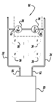
flow. Initially, the water is not hot, but rather cold or warm. After a period
of time the
water becomes hot and is used. This approach not only costs the user time, it
also
wastes a substantial amount of water because the water flows down a drain
while the
water temperature slowly rises to the desired temperature.
[3] The problem described arises not only in hot water supply systems, but in
any hot
fluid supply system using piping to deliver hot and cold fluid from a source
to a
discharge valve. The temperature of the fluid within a hot fluid supply pipe
of a hot
fluid supply system decreases to an ambient temperature over time when the
fluid is
not flowing. As a result, when hot fluid is desired, the user needs to allow
the fluid to
flow until the temperature at the discharge valve reaches the desired
temperature.
[4] Two methods are commonly used to maintain the temperature of water at a
discharge valve. Both methods involve recirculating hot water from the hot
water side
of a hot water supply system back to a source, such as a hot water heater. One
method
involves routing a pipe from the hot water supply pipe at the furthest fixture
within a
plumbing system back to the water heater which supplies the hot water to the
plumbing
system. The installation of such a return line has a substantial cost.
Typically, it
involves the routing of many feet of piping throughout a house.
[5] A second method involves installing a pump in proximity to a discharge
valve
between the hot water supply pipe and the cold water supply pipe connected to
that
discharge valve. This will control water temperature near the fixture by
shunting water
from the hot water supply pipe to the cold water supply pipe. Often the pump
is
electrically powered and may be controlled by timing controls, temperature
controls or
a manual switch which cause the pump to operate at desired times or at desired
water
temperatures. Such a pump may also be used to enhance the performance of a hot
water supply system employing the return line method described above. The pump
is
installed within the return line to cause the water to be returned to the hot
water source.
[6] Several problems are associated with using water pumps. The water pump has
a
CA 02607818 2007-11-05
WO 2006/120616 PCT/IB2006/051395
2
significant cost. The water pump requires electrical power, at a cost, to
operate and
install. The water pump has a tendency to malfunction and require repairs over
time.
The water pump emits undesirable noise. Since the water pump is electrically
operated
within the proximity of water it presents a potential electrical shock safety
hazard.
[7] Attempts to address these problems can be found within the following
patents:
5,323,803, 5,622,203 and 5,819,785.
[8] There is a need for a simple mechanical fluidic device which will control
and
maintain fluid temperature at or near a discharge valve. In particular, there
is a need for
such a device which will control and maintain water temperature at or near a
discharge
valve. The device should be able to be manufactured at a low cost. It should
not emit
noise. It should not require electrical power for operation. The maintained
and
controlled temperature should be manually adjustable from a position outside
of the
fluid. There is also a need for an adjustable temperature controlled faucet
and a
temperature controlled hot water supply system having these features.
[9] The present invention satisfies these needs.
SUMMARY
[10] The preferred use for the present invention is the maintenance of water
temperature.
One version of the invention is an apparatus for maintaining water
temperature. An
apparatus for maintaining water temperature is comprised of a water inlet, a
mechanical ambient air temperature controlled water shutoff valve, a water
check
valve and a water outlet. Preferably the water inlet is shaped and sized to
connect the
apparatus to a hot water supply pipe. This will permit the apparatus to be
easily
connected to the hot water side of a water supply system having a hot water
side and a
cold water side. Preferably, the water outlet is shaped and sized to connect
the
apparatus to a cold water supply pipe. This will permit the apparatus to be
easily
connected to the cold water side of the water supply system.
[11] Typical of such water supply systems is a residential water supply system
comprised of a hot water heater and associated pipes. The source of the hot
water side
of the water supply system is a hot water outlet emanating from the water
heater. A hot
water supply pipe is connected to the hot water outlet. A cold water inlet
also emanates
from the hot water heater. The water supply system also has a cold water
source. The
cold water source is connected, directly or indirectly, to the cold water
inlet of the
water heater and a cold water supply pipe. Preferably, the water outlet of the
apparatus
is shaped and sized to connect to the cold water supply pipe.
[12] The ambient air temperature controlled water shutoff valve is
mechanically
operated. This avoids the noise, operating cost, electrical installation cost,
electrical
shock hazard and breakdown tendency of an electrically controlled water
shutoff valve.
Since this invention relies upon thermal convection and pressure balancing of
the water
CA 02607818 2007-11-05
WO 2006/120616 PCT/IB2006/051395
3
supply system, and does not use a pump, the noise, operating cost, electrical
in-
stallation cost, electrical shock hazard and breakdown tendencies of
electrical pumps
are also avoided. The mechanical ambient air temperature controlled shutoff
valve has
an air sensor which controls the opening and closing of the valve. The
mechanical
ambient air temperature controlled shutoff valve opens upon a falling
temperature. As
the water cools, the reduced water temperature is communicated to the air
sensor by air
ambient to the valve. The reduced temperature at the air sensor causes the
valve to
open. It permits water to flow only when the water temperature falls below a
selected
temperature. Preferably, the mechanical ambient air temperature controlled
water
shutoff valve is a commonly available residential or commercial radiator
valve. The
mechanical ambient air temperature controlled water shutoff valve is connected
in
series with the water inlet of the apparatus. This permits the starting and
stopping of
the flow of water based upon the temperature of the water.
[13] The water check valve is connected in series with the ambient air
temperature
controlled water shutoff valve. The check valve is aligned to permit the flow
of water
in a direction from hot to cold only. The water outlet of the apparatus is
connected in
series with the ambient air temperature controlled water shutoff valve and the
check
valve. The ambient air temperature controlled water shutoff valve and the
check valve
are positioned between the water inlet and the water outlet of the apparatus.
Optimal
results are obtained by installing the apparatus at the fixture furthest from
the hot water
source. This will control and maintain the water temperature at the other
fixtures along
the hot water branch circuit of the plumbing system.
[14] Optionally, the apparatus may be used to regulate water temperature at a
faucet or a
discharge valve. The faucet or discharge valve has a hot water inlet and a
cold water
inlet. The second branch of a first tee having three branches is connected to
the water
inlet of the apparatus. The first branch of the first tee is sized and shaped
to connect to
the hot water inlet of the faucet or discharge valve. The third branch of the
first tee is
sized and shaped to connect to a hot water supply pipe for connecting the
apparatus to
the hot water side of a water supply system. The second branch of a second tee
having
three branches is connected to the water outlet of the apparatus. The first
branch of the
second tee is sized and shaped to connect to the cold water inlet of the
faucet or
discharge valve. The third branch of the second tee is sized and shaped to
connect to a
cold water supply pipe for connecting the apparatus to the cold water side of
a water
supply system. The temperature of water at the junction of the three branches
of the
first tee is controlled and maintained when a hot water supply pipe is
connected to the
third branch of the first tee, a cold water supply pipe is connected to the
third branch of
the second tee, the first branch of the first tee is connected to the hot
water inlet of the
faucet or discharge valve and the first branch of the second tee is connected
to the cold
CA 02607818 2007-11-05
WO 2006/120616 PCT/IB2006/051395
4
water inlet of the faucet or discharge valve.
[15] Preferably, insulation surrounds the ambient air temperature controlled
water
shutoff valve. The insulation isolates the ambient air temperature controlled
water
shutoff valve from outside ambient air and reduces the temperature response
time of
the ambient air temperature controlled water shutoff valve. Generally the term
outside
ambient air refers to ambient air outside of and external to the insulation,
while the
term ambient air refers to air within the insulation which is in contact with
the shutoff
valve. During the operation of the apparatus heat from the water is
transferred to the
ambient air surrounding the apparatus. This ambient air is enclosed within the
insulation. The second type of ambient air is the air outside of the
insulation. The heat
from the ambient air within the insulation is transferred to an ambient air
sensor on the
ambient air temperature controlled water shutoff valve. The insulation
facilitates a
more rapid temperature response by the ambient air temperature controlled
water
shutoff valve by maximizing the amount of water heat transferred to the air
sensor, by
minimizing the amount of water heat bled off to the ambient air outside of the
insulation. Preferably, the surrounding insulation is provided by enclosing
the ambient
air temperature controlled water shutoff valve within an insulation box.
[16] Although this invention is principally directed toward water temperature
control
and has been described in terms of water based elements, it may also be used
to
maintain and control the temperature of many fluids. Substituting the term
fluid for
water within the above description describes the invention as a fluid
temperature
control device.
[17] Another version of this invention is an adjustable temperature controlled
faucet.
The temperature controlled faucet is comprised of a faucet having a hot water
inlet and
a cold water inlet and an apparatus for regulating water temperature
configured as a
temperature control assembly. The temperature control assembly is comprised of
a
water inlet, a mechanical ambient air temperature controlled water shutoff
valve, a
water check valve, a water outlet, a first tee having three branches and a
second tee
having three branches. The shutoff valve opens upon a falling temperature. It
is
connected in series with the water inlet. It starts and stops the flow of
water based upon
the temperature of the water, as previously described. The temperature of the
water is
communicated to an air sensor on the valve. The water check valve is connected
in
series with the ambient air temperature controlled water shutoff valve. It is
aligned for
permitting the flow of water in a direction from hot to cold only. The water
outlet is
connected in series with the ambient air temperature controlled water shutoff
valve and
the check valve. The ambient air temperature controlled water shutoff valve
and the
check valve are positioned between the water inlet and the water outlet. The
first
branch of the first tee is connected to the hot water inlet of the faucet. The
second
CA 02607818 2007-11-05
WO 2006/120616 PCT/IB2006/051395
branch of the first tee is connected to the inlet of the temperature control
assembly. The
third branch of the first tee is sized and shaped to connect to a hot water
supply pipe
for connecting the temperature control assembly to the hot water side of a
water supply
system having a hot water side and a cold water side. The first branch of the
second tee
is connected to the cold water inlet of the faucet. The second branch of the
second tee
is connected to the outlet of the temperature control assembly. The third
branch of the
second tee is sized and shaped to connect to a cold water supply pipe for
connecting
the temperature control assembly to the cold water side of the water supply
system.
The temperature of water at the junction of the three branches of the first
tee is
controlled and maintained when a hot water supply pipe is connected to the
third
branch of the first tee and a cold water supply pipe is connected to the third
branch of
the second tee. Preferably, the temperature controlled faucet further
comprises
insulation surrounding the ambient air temperature controlled water shutoff
valve. The
insulation isolates the ambient air temperature controlled water shutoff valve
from
ambient air outside of the insulation and reduces the water temperature
response time
of the ambient air temperature controlled water shutoff valve, as previously
described.
[18] An additional version of the invention is a temperature controlled hot
water supply
system. The temperature controlled hot water supply system is comprised of a
hot
water heater, a hot water supply pipe, a cold water supply pipe and an
apparatus for
maintaining water temperature configured as a temperature control assembly.
The
temperature control assembly is comprised of a water, a water outlet, a
mechanical
ambient air temperature controlled water shutoff valve, and a water check
valve. The
hot water heater has a cold water inlet and a hot water outlet. The hot water
supply
pipe has two terminations. One termination is connected to the hot water
outlet of the
water heater. The cold water supply pipe also has two terminations. One
termination is
connected to the cold water inlet of the water heater. The ambient air
temperature
controlled water shutoff valve opens upon a falling temperature. It has an air
sensor
which controls the opening and closing of the valve. The temperature of the
water is
communicated to the air sensor by air ambient to the valve. Preferably, the
valve is a
commonly available residential or commercial radiator valve. The valve is
connected
in series with the water inlet of the temperature control assembly. It is
positioned to lie
between the water inlet of the temperature control assembly and the water
outlet of the
temperature control assembly. The shutoff valve starts and stops the flow of
water
based upon the temperature of the water. The check valve is connected in
series with
the water shutoff valve and the water outlet of the temperature control
assembly. It is
aligned for permitting the flow of water in a direction from hot to cold only.
The
temperature control assembly water inlet is connected to the other hot water
supply
pipe termination. The temperature control assembly water outlet is connected
to the
CA 02607818 2007-11-05
WO 2006/120616 PCT/IB2006/051395
6
other cold water supply termination. The flow of water between said other
termination
of the hot water supply pipe and said other termination of cold water supply
pipe is
regulated based upon water temperature, as previously described the to. The
temperature of water within the hot water supply pipe is also controlled and
maintained. Preferably, the temperature controlled hot water supply system
further
comprises insulation surrounding the ambient air temperature controlled water
shutoff
valve. The insulation isolates the ambient air temperature controlled water
shutoff
valve from ambient air outside of the insulation and reduces the water
temperature
response time of the ambient air temperature controlled water shutoff valve,
as
previously described.
DRAWINGS
[19] These and other features, aspects, and advantages of the present
invention will
become better understood with regard to the following description, appended
claims,
and accompanying drawings where:
[20] Figure 1 is a schematic depiction of an apparatus for maintaining fluid
temperature
connected to a discharge valve to create a temperature controlled faucet.
[21] Figure 2 is a schematic depiction of an apparatus for maintaining fluid
temperature,
configured as a temperature control assembly, connected to a hot water supply
pipe
and a cold water supply pipe emanating from a hot water heater to create a
temperature
controlled hot water supply system.
[22] Figure 3 is a schematic depiction of a temperature controlled hot water
supply
system created by connecting an apparatus for maintaining water temperature,
configured as a temperature control assembly, to the distal end of a hot water
supply
pipe connected to a water heater and to the distal end of a cold water supply
pipe
connected to the water heater.
[23] Figure 4 is a perspective view of an apparatus for maintaining water
temperature
enclosed within an insulation box with a door, wherein the door is closed.
[24] Figure 5 is a perspective view of the apparatus for maintaining water
temperature
enclosed within an insulation box with a door of Figure 4, wherein the door is
open.
[25] Figure 6 is an elevation view of a radiator valve used as a mechanical
ambient air
temperature controlled fluid shutoff valve within an apparatus for maintaining
fluid
temperature.
[26] Figure 7 is a sectional elevation view of the radiator valve of Figure 6.
DETAILED DESCRIPTION
[27] The preferred embodiment of an apparatus for maintaining water
temperature is il-
lustrated in Figure 5. It is schematically depicted within Figure 1. The
apparatus for
regulating water temperature is comprised of a water inlet 22, a mechanical
ambient air
CA 02607818 2007-11-05
WO 2006/120616 PCT/IB2006/051395
7
temperature controlled water shutoff valve 24, a water check valve 26 and a
water
outlet 28. The ambient air temperature controlled water shutoff valve 24 is me-
chanically, rather than electrically, operated. The shutoff valve 24 is a
valve which
opens upon a falling temperature. The shutoff valve 24 has an air sensor 27
which
controls the opening and closing of the valve 24. The valve 24 is connected in
series
with the water inlet 22. The shutoff valve 24 starts and stops the flow of
water based
upon the temperature of the water, as communicated to the air sensor.
Preferably, the
shutoff valve 24 is a valve having a manually adjustable shutoff temperature.
This will
permit the regulated water temperature to be varied. A manually adjustable
temperature setpoint controller 25 is positioned upon the external periphery
of the
mechanical ambient air temperature controlled water shutoff valve 24, outside
of the
water jacket. As the water cools, the ambient air 23 surrounding the valve 24
cools.
The temperature of the ambient air 23 is detected by an air sensor 27 on the
mechanical
ambient air temperature controlled water shutoff valve 24. The temperature at
which
the mechanical ambient air temperature controlled water shutoff valve 24 opens
is set
by the manually adjustable temperature setpoint controller 25. Common
residential and
commercial heating radiator valves 24a, such as the radiator valve shown in
Figure 6
and Figure 7, have the features of the mechanical ambient air temperature
controlled
water shutoff valves described herein. Because the manually adjustable
temperature
setpoint controller 25 is positioned outside of the water, it allows easy
access. The
apparatus does not need to be disassembled to change the temperature setpoint
of the
valve 24.
[28] The water check valve 26 is connected in series with the ambient air
temperature
controlled water shutoff valve 24. The check valve 26 is aligned for
permitting the
flow of water in a direction from hot to cold only.
[29] The water outlet 28 is connected in series with the ambient air
temperature
controlled water shutoff valve 24 and the water check valve 26. The ambient
air
temperature controlled water shutoff valve 24 and the water check valve 26 are
positioned between the water inlet 22 and the water outlet 28. The check valve
26
prevents cold water from mixing with hot water near the water inlet 22,
thereby
causing a reduction of water temperature within any hot water located within
the water
inlet 22. The preferred material for the water inlet 22, the body of the water
shutoff
valve 24 and the water outlet 28 is brass. Preferably, the check valve 26 is
constructed
from plastic and rubber and is sealed with a rubber 0-ring. Such check valves
26 are
commonly available in the plumbing industry.
[30] The apparatus for regulating water temperature may be used to create a
temperature
controlled hot water supply system, as shown in Figures 2 and 3, or a
temperature
controlled faucet, as shown in Figure 1. If it is to be used to create a
temperature
CA 02607818 2007-11-05
WO 2006/120616 PCT/IB2006/051395
8
controlled hot water supply system, as shown in Figures 2 and 3, the water
inlet 22 is
shaped and sized to connect the apparatus to a hot water supply pipe 32 and
the water
outlet 28 is shaped and sized to connect the apparatus to a cold water supply
pipe 34.
This will allow the inlet 22 of the apparatus to be connected to the hot water
side of a
water supply system and the outlet 28 of the apparatus to be connected to the
cold
water side of a water supply system. If the apparatus is to be used to create
a
temperature controlled faucet, as shown in Figure 1, a first tee 30 having
three
branches is connected at its second branch to the water inlet 22. The first
branch of the
first tee 30 is sized and shaped to connect to the hot water inlet 38 of a
faucet 36
having a hot water inlet 38 and a cold water inlet 40. The third branch of the
first tee
30 is sized and shaped to connect to a hot water supply pipe 32. This permits
connecting the apparatus to the hot water side of a water supply system.
Additionally,
if the apparatus is to be used to create a temperature controlled faucet, a
second tee 31
having three branches is connected at its second branch to the water outlet 28
of the
apparatus. The first branch of the second tee 31 is sized and shaped to
connect to the
cold water inlet 40 of the faucet 36 having a hot water inlet 38 and a cold
water inlet
40. The third branch of the second tee 31 is sized and shaped to connect to a
cold water
supply pipe 34. This permits connecting the apparatus to the cold water side
of a water
supply system. The temperature of the water at the junction of the three
branches of the
first tee 30 is controlled and maintained when a hot water supply pipe 32 is
connected
to the third branch of the first tee 30, a cold water supply pipe 34 is
connected to the
third branch of the second tee 31, the first branch of the first tee 30 is
connected to the
hot water inlet 38 of the faucet 36 and the first branch of the second tee 31
is connected
to the cold water inlet 40 of the faucet 36. Preferably, the tees 30, 31 are
constructed
from brass and attached to the apparatus water inlet 22 and the apparatus
water outlet
28 by threaded connections. For optimal performance the ambient air
temperature
controlled water shutoff valve 24 is surrounded by an insulation box 80 having
a door.
The insulation box 80 isolates the ambient air temperature controlled water
shutoff
valve 24 from outside ambient air and reduces the temperature response time of
the
ambient air temperature controlled water shutoff valve 24,as previously
described.
[31] To create a temperature controlled faucet, the version of the apparatus
for
maintaining water temperature having a first tee 30 connected to the water
inlet 22 of
the apparatus and a second tee 31 connected to the water outlet 28 of the
apparatus, as
described above, is connected to a faucet 36 having a hot water inlet 38 and a
cold
water inlet 40, as shown in Figure 1. The first branch of the first tee 30 is
connected to
the hot water inlet 38 of the faucet 36. The first branch of the second tee 31
is
connected to the cold water inlet 40 of the faucet 36. When a hot water supply
pipe 32
is connected to the third branch of the first tee 30 and a cold water supply
pipe 34 is
CA 02607818 2007-11-05
WO 2006/120616 PCT/IB2006/051395
9
connected to the third branch of the second tee 31, the temperature of water
at the
junction of the three branches of the first tee 30 is controlled and
maintained. Optimum
performance is obtained by enclosing the apparatus for regulating water
temperature
within an insulation box 80.
[32] To create a temperature controlled hot water supply system, the version
of the
apparatus for maintaining water temperature without the tees 30, 31, as
described
above, is used. The temperature controlled hot water supply system is
comprised of a
hot water heater 50, a hot water supply pipe 32, a cold water supply pipe 34
and the
apparatus for regulating water temperature, as shown in Figures 2 and 3. The
apparatus
for regulating water temperature without the tees 30, 31 is configured as and
functions
as a temperature control assembly 68. The hot water heater 50 has a cold water
inlet 52
and a hot water outlet 54. The hot water supply pipe 32 has two terminations.
One
termination is connected to the hot water outlet 54 of the hot water heater
50. The cold
water supply pipe 34 also has two terminations. One termination is connected
to the
cold water inlet 52 of the hot water heater 50. The temperature control
assembly 80 is
comprised of a water inlet 22, a water outlet 28, a mechanical ambient air
temperature
controlled water shutoff valve 24 and a water check valve 26. The ambient air
temperature controlled shutoff valve 24 opens upon a falling temperature. The
valve 24
has an air sensor 27. Preferably, the valve is a radiator valve 24a. It is
connected in
series with the water inlet 22 of the temperature control assembly. The
ambient air
temperature controlled shutoff valve 24 starts and stops the flow of water
based upon
the temperature of the water, as communicated to the air sensor 27. The water
check
valve 26 is connected in series with the ambient air temperature controlled
water
shutoff valve 24 and the water outlet 28 of the temperature control assembly.
The
check valve 26 is aligned for permitting the flow of water in a direction from
hot to
cold only. The temperature control assembly water inlet 22 is connected to the
other
termination of the hot water supply pipe 32. The temperature control assembly
68
water outlet 28 is connected to the other termination of the cold water supply
pipe 34.
This causes the flow of the water between said other termination of the hot
water
supply pipe 32 and said other termination of the cold water supply pipe 34 to
be
regulated based upon the water temperature. It further causes the temperature
of the
water within the hot water supply pipe 32 to be controlled and maintained. For
optimal
performance an insulation box 80 surrounds the ambient air temperature
controlled
shutoff valve 24. This isolates the ambient air temperature controlled water
shutoff
valve 24 from outside ambient air and reduces the temperature response time of
the
ambient air temperature controlled water shutoff valve 24.