Note : Les descriptions sont présentées dans la langue officielle dans laquelle elles ont été soumises.
CA 02608289 2007-11-05
PCT/EP2006/004502
OSCILLATION DECOUPLING DEVICE
TECHNICAL FIELD
The invention relates to an oscillation decoupling device with a load-
receiving
element which is mounted in an oscillating manner relative to a support unit
at
least along an active direction along which the at least one part of the load
is
applied, and with at least one sensor-actuator unit which detects an
oscillation
of the element due to the load and acts against the oscillation of the element
by
means of actuators.
STATE OF THE ART
In almost all fields of the art oscillation problems arise which must be
solved, for
example by decoupling a partial structure from its vibrating environment.
Typical
examples of this are mountings of measurement sensitive measuring apparatus
in faboratories for decoupling impact noise and other disturbances by means of
suitably designed damping systems, but similar problems also arise in aviation
and space systems. On the other hand it is necessary to decouple sources of
disturbing vibrations from a structure surrounding them, as frequently
encountered, for example, in the mountings of drive units in vehicles,
aircraft or
ships.
For this purpose differently designed oscillation decoupling devices are known
which exert a purely passive oscillating action with the use of elastic or
damping
materials. However, the disadvantage of these devices lie in the fact that it
is
not possible to adapt to changing system characteristics in order to maintain
as
optimum an oscillation damping as possible. Moreover, although the use of the
softest possible mountings results in effective oscillation damping or
oscillation
decoupling, this is also associated with imprecise mounting of the decoupled
system. On the other hand, although stiffer mounting systems allow more
precise system positioning, the quality of the oscillation decoupling suffers
CA 02608289 2007-11-05
- 2 -
correspondingly, particularly in the case of oscillations with small
amplitudes
and high frequencies.
In addition to purely passively designed oscillation decoupling systems,
mechatronic and adaptronic solutions are being used to an increasing extent,
the oscillation decoupling here being achieved by means of actively introduced
compensation signals which serve for the controlled activation of
etectrodynamic actuators, magnetic bearings or piezo-actuators which are
integrated in the region of oscillation decoupled interfaces and make an
active
contribution to oscillation decoupling, in the sense of an oscillation
reduction, for
the specific coupling of counter-oscillations.
Reference is made, by way of example, to US 5 645 260, which describes an
oscillation decoupling device which is provided between a load and a vibrating
background. The load rests essentially on an elastic support structure in the
form of a jib angle along whose jib elements, orientated perpendicularly to
each
other, are installed flat piezo-actuators which are capable of inducing both
horizontally and vertically directed oscillations into the jib angle due to
their
arrangement orientated orthogonally to each other, with the ultimate object of
effective oscillation decoupling. The prior art arrangement of the piezo-
actuators
also has the advantage that the actuators are largely protected from damaging
mechanical loads by the support structure.
A further modular interface for damping mechanical oscillations is disclosed
in
DE 103 61 481 Al, which provides for a plurality of energy converter systems
kinematically coupled to each other between a basic connecting element and a
load connecting element, which systems, in a similar manner to the oscillation
decoupling system explained above, are based on the specific control of
piezoelectric converter materials. However, the energy converter systems,
designed as piezoelectric stacking actuators, are operated under mechanical
pretension and are protected against loading by shearing and torsion, hence
the
need for comprehensive mechanical protective measures for the actuators.
CA 02608289 2007-11-05
- 3 -
The oscillation decoupling devices of prior art predominantly represent
systems
that are individually adapted to certain interfaces between two components to
be oscillation decoupled. These systems cannot be used in other systems to be
decoupled or can only be used in them with expensive design modifications.
Moreover, the integration of the piezo-actuators in the structure concerned
represents a high construction expenditure which is unavoidably associated
with high production and assembly costs.
REPRESENTATION OF THE INVENTION
The object of the invention is to further develop an osciliation decoupling
device
with a load-receiving element which is mounted in an oscillating manner
relative
to a support unit at least along an active direction along which at least part
of
the load is applied, and with at least one sensor-actuator unit which detects
an
element that is oscillating due to the load and acts against the oscillation
of the
element by means of actuators, so that the device can be used universally and
represents no special solution to an individual oscillation problem. The
device
should on the one hand have the advantages of an elastically passive mounting
with actuating components, and should at the same time provide the possibility
of integrating all the components in one structural unit for independent
operation. This should provide a system that is easy to handle, is robust and
can be used under difficult environmental conditions.
The object of the invention is achieved as indicated in Claim 1. Features
advantageously further developing the inventive concept constitute the subject
matter of the dependent claims and may be deduced from the description, with
particular reference to the exemplary embodiments.
According to the inventive solution an oscillation decoupling device is
represented with a load-receiving element which is mounted In an oscillating
manner relative to a support unit at least along an active direction along
which
CA 02608289 2007-11-05
- 4 -
at least part of the load is applied, and with at least one sensor-actuator
unit
which detects an element oscillating due to the load and acts against the
oscillation of the element by means of actuators, characterised in that the
support unit is modularly configured and serves as a support structure for at
least one unit that receives the element and is elastically deformable at
least in
the active direction of the load. At least one actuator influencing the
deformation
is applied to the at least one unit, or is integrated in the unit, so that the
actuator
initiates a deformation acting against the elastic deformation due to the load
inside the unit.
The inventive device is based on the modular concept and the associated
simple, versatile applicability of the inventive device. The support unit
serving as
the support structure for the elastic unit is designed as a fixed module
housing
which accommodates the elastically deformable unit provided for oscillation
absorption and the actuators attached to or provide on it for the specific
introduction of counter-oscillations, the unit and actuators being protected
from
disturbing external oscillation influences. The stiffness of the elastically
deformable unit must be chosen according to the size and intensity of a static
andlor dynamic extemal load to be decoupled, which unit, in a preferred
embodiment, is designed in the manner of a membrane and spans an internal
free cross-sectional area of the module housing so that is freely supporting,
and
is connected on the inside, in at least two regions, preferably throughout its
circumferential edge, to the module housing. The elasticity and stiffness or
stroke of the flat designed, elastically deformable unit can therefore be
correspondingly adapted based on the choice of material, shape and thickness.
The elastically deformable unit therefore represents the elastic, passive part
of
the oscillation decoupling system, and is connected indirectly or directly to
an
element which is preferably designed in the manner of a rod and is orientated
perpendicularty to the superficial extension of the elastically deformable
unit
along which the extemal load to be decoupled acts, which ultimately results in
a
deflection or deforrnation of the elastically deformable element
perpendicularly
to the superricial extension of the element.
CA 02608289 2007-11-05
- 5 -
A further possibility of adjusting the stiffness behaviour of the elastic,
passive
part of the oscillation decoupling system consists in providing two or more
elastically deformable units inside a module housing which can be mechanically
connected in parallel or in series. In the former case a coupling of the at
least
two elastically deformable units to an element designed in the manner of a rod
must be provided, whilst in the latter case this coupling is not provided, and
the
elastically deformable units are therefore able to absorb a proportion of the
external static and/or dynamic loads.
A mechanically serial and/or parallel connection of two or more modules is
also
possible. In this case the parallel connection of modules serves to increase
the
oscillation stroke. In this case the elements of the modules designed in the
manner of rods are not connected to each other, whilst the serial connection
serves to increase stiffness and hence to transmit higher forces. In a
preferred
embodiment the elements of the modules designed in the manner of rods are
connected to each other.
Moreover, combinations of modules connected mechanically in parallel and in
series are conceivable. For a clearer representation of the inventive concept
it is
assumed in the following that only one single elastically deformable unit
designed in the manner of a membrane is provided inside the previously
described module housing.
For an effective reduction of the oscillations induced by an externally
applied
dynamic load inside the elastically deformable unit designed in the manner of
a
membrane, the latter is connected to at least one, preferably a plurality of
flat
designed electromechanical converters or actuators which, when suitably
controlled; give rise to controlled deformation of the elastically deformed
unit
designed in the form of a membrane. Piezoelectric plate actuators, which are
applied to and/or integrated in the surface of the elastically deformable unit
designed in the manner of a membrane, and which expand or contract due to
CA 02608289 2007-11-05
- 6 -
the application of an electric voltage, as a result of which they introducing
a
bending moment into the elastically deformable unit and produce a bend
perpendicular to the superficial extension of the unit, are particularly
suitable as
electromechanical converters. This enables actuators to intervene in the
oscillation behaviour of the elastically deformable unit in a specifically
controlled
and regulated manner in or against the active direction of the external load.
In a preferred embodiment at least one sensor detecting the deformation of the
unit is applied to the elastically deformable unit, or is integrated in the
unit, for
detecting the current oscillation state of the elastically deformable unit. In
a
similar manner to the actuator principle explained above, an electromechanical
converter, for example in the form of a piezoelectric plate sensor, which
generates a voltage signal that can be evaluated by measurement by way of a
deformation, is also suitable for the sensor, which signal is used for
controlling
or regulating the actuators connected to the elastically deformable unit.
Alternatively to or in combination with sensorics connected directly to the
elastically deformable unit, it is also possible to install corresponding
sensors,
for example in the form of acceleration sensors, in the region of the load or
the
body to be decoupled, for example directly on the oscillating body connected
to
the element or in the load path of the load along the element which is
connected
to the elastically deformable unit designed in the manner of a membrane.
Independently of the different designs and installation of the sensors, it is
necessary to detect the oscillation behaviour of the at least one elastically
deformable unit integrated inside the module housing. in order to generate
control or regulating signals for activating the at least one actuator
connected to
the elastically deformable unit, with the object of reducing the externally
applied
oscillations along the elastically deformable unit designed in the manner of a
membrane.
The processing of the signals generated by the sensors, and the generation of
corresponding control signals for the actuators, are preferably carried out
with
suitable controi logic which is preferably based on digital signal processing
and,
CA 02608289 2007-11-05
- 7 -
for reasons of cost, can be implemented on so-called low-cost embedded
ptatforms such as DSP, microcontrollers and FPGA.
In principle it is possible to install any electrical components required both
for
energy supply and signal evaluation together with the components explained
above inside the module housing. in order to obtain and optimise the
modularity
of the inventive device it would appear advantageous to provide a modularly
configured electronic unit that can be integrated in the module housing or can
be applied to the existing module housing for energy supply and/or signal
control and/or signal evaluation of the at least one sensor and actuator. It
is
appropriate to design the electronic unit required for the energy supply and
signal control of the individual actuator modules combined together in the
form
of a separate electronic module, particulariy for the purpose of combining two
or
more module housings, each of which has at least one elastically deformable
unit with corresponding sensorics and actorics and are connected by means of
a common element for receiving an external static and/or dynamic load are
designated as actuator modules in the following. The electronic module has its
own module housing and can be combined to form an entire system by means
of a suitable mechanical, as well as electrical connection system via at least
one of the combined actuator modules.
Of particular interest is the design of the inventive oscillation decoupling
device
in the form of a completely autonomously and largely independently operating
unit, i.e. all the components required for effective oscillation decoupling,
including the energy supply, are joined together in the form of individual
modules to form one entire system which can be inserted as an interface
between an oscillating body and a corresponding base surface.
In the case of an adaptively configured actuator control for specific
deflection of
the membrane-like configured elastically deformable uni# inside an actuator
module, it is possible to supply the reference signals required for
controlling the
actuators connected to the elastically deformable unit from outside, for
example
CA 02608289 2007-11-05
- 8 -
wirelessly using an intrinsically known telemetry technique. It is therefore
possible, for example, correspondingly to suppress disturbing vibrations of a
rotary machine by externalty gained speed-synchronous trigger signals, which
are supplied telemetrically as reference signals to the actuators inside the
actuator modules. In this case no further sensors are required for detecting
the
current oscillating state of the elastically deformable unit, particularly as
the
actuators are controlled by extemally predetermined trigger signals which are
frequently available via existing bus systems. If such extemal trigger signals
are
not available, there is also the possibility of estimating the interference
signal by
means of one or a plurality of acceleration sensors applied to the
interference
source, as a result of which suitable reference signals can also be generated.
The use of digital signal processing for control implementation, particularly
when a plurality of devices configured modularly according to the invention is
used, which are provided, for example, on a vibrating machine for support at
different points for oscillation decoupling, provides the interesting
possibility of
exchanging data with an extemally provided central computer. For this purpose
each individual oscillation decoupling module, each of which consists of one
actuator and one electronic module, provides a telemetry unit for wireless
data
transmission. Obviously it is also possible, but in most cases associated with
technical and design difficulties, to data to be exchanged with a central
computer on a wire-bound basis. The reference signals controlling the
individual
oscillation modules can be optimised by the central collection and evaluation
of
all the information on an oscillating system. lt is also possible to carry out
self-
diagnoses in each individual oscillation decoupling module on the basis of
digital signal processing, which diagnoses serve to optimise control
parameters
for controlling the individual actuator modules by feedback to the central
computer.
CA 02608289 2007-11-05
- 9 -
BRIEF DESCRIPTION OF THE INVENTION
The invention is described by way of example below, without limiting the
general inventive concept, by means of exemplary embodiments with reference
to the drawings, in which:
Figs. 1 a, b show a schematised longitudinal section and partial longitudinal
section, respectively, through an actuator module,
Fig. 2 shows a schematised longitudinal section representation through a
modularly configured oscillation decoupling device,
Fig. 3 shows a schematised perspective representation of the module sown in
Fig. 2,
Fig. 4 shows a module arrangement for the oscillation decoupling of an
oscillating unit,
Figs. 5a-c show a schematised cross-sectional representation through an
actuator module with an elastically deformable unit,
Fig. 6 shows the mechanical series connection of two actuator modules, and
Fig. 7 shows the mechanical parallel connection of two actuator modules.
METHODS OF IMPLEMENTING THE INVENTION, COMMERCIAL
APPLICABILITY
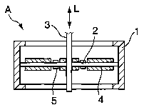
Figure 1 a shows a schematised longitudinal section representation through an
actuator module which is enclosed by a module housing 1 designed essentially
in the shape of a hollow cylinder. Module housing I serves as a supporting
structure for an electrically deformable unit 2 designed in the manner of a
CA 02608289 2007-11-05
- 10 -
membrane and installed inside module housing 1, which unit, as a flat element
similar to a leaf spring, at least partially spans the internal free housing
cross-
section and is fixedly connected to its peripheral circumferential edge to the
inner wall of module housing 1. An element 3, designed in the shape of a rod,
is
installed centrally to the flat or membrane-like configured elastically
deformable
unit 2, the longitudinal rod extension of which element is orientated
essentially
perpendicularly to the plane of the flat design of unit 2, and along which an
extemal load L is applied to actuator module A, and in particular to the
elastically deformable unit provided in actuator module A.
Element 3 may be connected fixedly or releasably to elastically deformable
unit
2, for example by way of a screw connection. Elastically deformable unit 2 is
deformed perpendicularly to its superficial extension by the predesigned
introduction of a force from an extemal static or dynamic load L via element
3.
In order to counteract these externally induced deformations to which
elastically
deformable unit 2 is exposed, in an oscillating damping manner, flat designed,
energy converting actuators 4 are installed on the surfaces of the membrane-
like configured elastically deformable unit 2, these actuators preferably
produced from piezoceramic, lead-free piezoceramic, an electrostrictive
ceramic, PVDF (polyvinylidene fluoride), magnetostrictive alloys, bi-metals or
from a shape memory alloy or shape memory polymer, all converter materials
which are capable of changing their spatial shape in terms of their length by
means of an external electrical voltage supply.
Figure 1 b shows a schematised partial longitudinal section through an
actuator
module A sown in Figure 1a, with two flat designed piezo-actuators 41, 42
installed on the upper and lower side of elastically deformable unit 2, which
actuators are controlled in such a manner that piezo-actuator 42 installed on
the
upper side of inembrane-like configured elastically deformable uriil 2 is
shortened, whereas piezo-actuator 41 provided on the lower side is expanded.
As a result of this elastically deformable unit 2 experiences an upward
directed
CA 02608289 2007-11-05
- 11 -
curvature in the representation according to Figure 1 b, causing element 3 to
be
deflected upwards.
The principle of the oscillation decoupling provides for the actuator effected
deflection of elastically deformable unit 2, e.g. in exactly the opposite
phase to
the load L applied externally via element 3.
Furthermore a plurality of sensors 5 is installed on and/or integrated in the
upper and lower side of themembrane-like configured elastically deformable
unit 2, which sensors may also exist as the actuators produced from a
converter
material. Obviously it is possible to design the sensors as DMS's or the like,
in
order to detect the current deformation state and associated with the current
oscillation state of elastically deformable unit 2, and to generate
corresponding
sensor signals.
Figure 2 shows a schematised longitudinal section representation of an
oscillation decoupling module SM, consisting of two actuator modules Al and
A2 connected mechanically in parallel and an electronic module E connected to
actuator module A2. Actuator modules Al and A2 are correspondingly designed
according to the above statements relating to Figures 1 a and b, and each have
an elastically deformable unit 2, all of them connected to a single element 3
by
means of which the extemal load is applied to oscillation decoupling module
SM. For the energy supply, but in particular also for data evaluation and
controlled signal supply to actuators 2, an electronic module E is provided
which, for reasons of compact design, is formed in the same or a similar
manner in terms of housing design as actuator modules Al and A2. All modules
Al, A2 and E have mechanical interfaces which facilitate the coupling together
of the module units. The electronic module comprises a power conditioning unit
6, which supplies the energy for controlling the actuators, for example in the
case of piezo-actuators in the form of a voltage amplifier and components of
signal data evaluation unit 7 and 8, in which sensor data are supplied and
evaluated in order finally to generate control signals for activating the
actuators.
CA 02608289 2007-11-05
- 12 -
Provision is preferably made for the electrical contacting between the
electronic
components contained inside actuator modules Al and A2 and those in
electronic -module E by means of suitably designed connection contact points
(not shown), in order to conform to the modularity principle. Depending on the
loads applied, oscillafion decoupling module SM provides the possibility of
increasing the stiffness of the passively elastic parts, i.e. the elastically
deformable units, by adding further actuator modules.
Figure 3 shows, in schematised form, an oscillation decoupling module SM
composed of two actuator modules Al and A2 and an electronic module E, from
whose upper housing end projects element 3, by means of which external load
L is introduced and supported for the purposes of oscillation decoupling.
Oscillation decoupling module SM is fastened to a stable base 9 so that
precise
positioning is ensured. On the other hand the module could also be installed
on
an elastic structure, but this depends on the particular application.
The exemplary embodiment shown in Figure 4 provides for the oscillation
decoupling of an oscillating unit 10, which is mounted at four support points
P1,
P2, P3 and P4 on suitably designed oscillation decoupling modules SM. In this
design variant the individual oscillation decoupling modules SM have telemetry
units by means of which- the reference signals sent from central computer 11
for
controlling the actuators contained in oscillation decoupling modules SM are
transmitted and received. Similarly all sensorically detected data can be
evaluated centrally by means of such wireless data communications technology
on the oscillating state of unit 10 to guarantee optimised control of the
corresponding actuator modules inside oscillation decoupling modules SM.
A section through an actuator module in the plane of the membrane-like
configured elastically deformed unit 2 is shown in the cross-section diagrams
in
Figures 5a to c. In all cases module housing 1 is designed in the shape of a
hollow cylinder and has a membrane-like configured elastically deforrnable
unit
2 connected to module housing 1 along its entire circumferential edge. In
Figure
CA 02608289 2007-11-05
- 13 -
5a an annular designed actuator element 4 is provided on the surface of
elastically deformable unit 2, which element represents an internal
superficial
connection to unit 2. In the exemplary embodiment shown in Figure 5b the
membrane-like configured elastically deformable unit 2 has four recesses 12,
and is also connected on its surface to four strip-shape configured actuators
4.
Figure 5c also shows provides for an actuator in the form represented,
connected in the form of a strip to elastically deformable unit 2. All the
exemplary embodiments shown in Figure 5 serve specifically to deform the
membrane-like configured elastically deformable unit perpendicularly to its
plane, i.e. perpendicularly to the drawing plane, in order to achieve an
effect
that reduces the oscillating load, for example by introducing oscillations
that are
opposite in phase to the external load.
Fig. 6 shows, similariy to Fig. 2, a mechanical serial connection of Module Al
and A2, where, in contrast to the exemplary embodiment shown in Figure 2,
rod-like configured element 2 is constructed separately. Force L2 can be
applied by means of element 3' to elastically deformable unit 2 of lower
actuator
module A2, independently of force LI, which is applied by means of element 3"
to the elastically deformable unit of upper actuator module Al. !n the case of
such a serial arrangement and mode of operation of at least two actuators, the
actoric path can be doubled under sufficiently low active loads or low
stiffnesses, whereas in the coupled case according to the embodiment shown in
Figure 2, a doubling of the stiffness is achieved. An altemative to the
embodiment in Figure 2 is shown in Figure 7, which represents a further type
of
mechanical parallei connection of a plurality of actuator modules. In this
case
the two actuator modules Al and A2 are connected to each other by means of a
common base plate G. Similarly, elements 3 of actuator modules Al and A2 are
connected to each other by means of a yoke J, so that they are simultaneously
deflected by means of a common load L.
The oscillation decoupling module explained above therefore has the following
advantages:
CA 02608289 2007-11-05
- 14 -
- The system can be fully integrated and affords major advantages in terms of
mountability and robustness;
- The combination of a membrane-like configured elastically deformable unit
having a defined stiffness with the application and/or integration of flat
designed
actuators allows particularly compact design of an active-passive oscillation
decoupling system;
- Because of the additional application and/or integration of flat sensors on
the
membrane-like configured elastically deformable unit the robustness and
compactness of such an oscillation decoupling module can be improved.
- The specific use of digital signal processing opens up the possibility of
providing adaptive digital controls to ensure optimum oscillation decoupling
despite variations in the interference signals or in the system
characteristics.
- Furthermore, it is possible, on the basis of digital signal processing, to
provide
communication with an extem computer in order to allow the exchange of
diagnosis data. This improves the possibility of maintaining such a system,
particularly as the regions in which the oscillation decoupling modules are
arranged are in most cases difficult to access and cannot easily be removed
for
servicing purposes.
CA 02608289 2007-11-05
- 15 -
LIST OF REFERENCE NUMBERS
1 Module housing
2 Elastically deformable unit
3 Element
4 Actuator
Sensor
6 Energy unit
7, 8 Components of a signal data evaluation unit
9 Base
Oscillating unit
11 Central computer
12 Recess