Sélection de la langue

Search

Sommaire du brevet 2608689 

Énoncé de désistement de responsabilité concernant l'information provenant de tiers

Une partie des informations de ce site Web a été fournie par des sources externes. Le gouvernement du Canada n'assume aucune responsabilité concernant la précision, l'actualité ou la fiabilité des informations fournies par les sources externes. Les utilisateurs qui désirent employer cette information devraient consulter directement la source des informations. Le contenu fourni par les sources externes n'est pas assujetti aux exigences sur les langues officielles, la protection des renseignements personnels et l'accessibilité.

Disponibilité de l'Abrégé et des Revendications

L'apparition de différences dans le texte et l'image des Revendications et de l'Abrégé dépend du moment auquel le document est publié. Les textes des Revendications et de l'Abrégé sont affichés :

  • lorsque la demande peut être examinée par le public;
  • lorsque le brevet est émis (délivrance).
(12) Brevet: (11) CA 2608689
(54) Titre français: PROCEDE ET DISPOSITIF POUR REMPLIR DES CONTENANTS
(54) Titre anglais: DEVICE AND METHOD FOR FILLING CONTAINERS
Statut: Périmé et au-delà du délai pour l’annulation
Données bibliographiques
(51) Classification internationale des brevets (CIB):
  • B65B 65/00 (2006.01)
  • B65B 05/06 (2006.01)
  • B65B 05/08 (2006.01)
(72) Inventeurs :
  • WAECKERLIN, JUERG (Suisse)
(73) Titulaires :
  • ROBERT BOSCH GMBH
(71) Demandeurs :
  • ROBERT BOSCH GMBH (Allemagne)
(74) Agent: BORDEN LADNER GERVAIS LLP
(74) Co-agent:
(45) Délivré: 2014-06-10
(86) Date de dépôt PCT: 2006-04-21
(87) Mise à la disponibilité du public: 2006-11-30
Requête d'examen: 2011-04-11
Licence disponible: S.O.
Cédé au domaine public: S.O.
(25) Langue des documents déposés: Anglais

Traité de coopération en matière de brevets (PCT): Oui
(86) Numéro de la demande PCT: PCT/EP2006/061737
(87) Numéro de publication internationale PCT: EP2006061737
(85) Entrée nationale: 2007-11-16

(30) Données de priorité de la demande:
Numéro de la demande Pays / territoire Date
10 2005 023 810.6 (Allemagne) 2005-05-24

Abrégés

Abrégé français

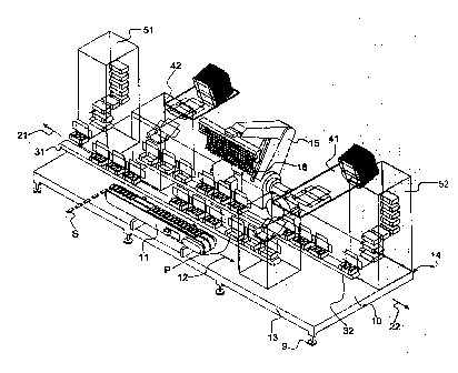
L'invention concerne un poste d'emballage (1) d'une machine à emballer servant à remplir des contenants (P) de marchandises (S), ce poste comprenant un dispositif de transport (11) pour amener les marchandises (S) sur une voie d'alimentation (12) ainsi qu'une première et une deuxième voie de chargement (21, 22) parallèles pour transporter les contenants (P). Les contenants (P) sont remplis par un dispositif de remplissage (15) qui saisit une ou plusieurs marchandises (S) de la voie d'alimentation (12) et met les marchandises (S) ainsi saisies dans un ou plusieurs contenants (P) sur une des voies de chargement (21 ou 22). Les voies de chargement sont constituées par une suite disposée dans le sens d'avancement des contenants (P) à remplir et comprenant un dispositif de dressage (41 ou 42), un dispositif de transport (31 ou 32) et un dispositif de fermeture (51 ou 52). Ce dispositif et ce procédé permettent de remplir plus rapidement des marchandises (S) dans des matériaux d'emballage (P) dans un espace relativement réduit, notamment sur une plate-forme (10).


Abrégé anglais


The invention relates to a packaging station (1) of a packaging machine for
filling
containers (P) with products (S), said station comprising a transport device
(11) for feeding
the products (S) along a feed path (12) and via first and second charging
paths (21, 22), which
run parallel to said feed path and transport the containers (P). The
containers (P) are filled by
means of a filling device (15), which is designed to seize one or more of the
products (S)
from the feed path (12) and to place said seized products (S) into one or more
containers (P)
on one or other of the charging paths (21 or 22). The charging paths (21 or
22) consist of the
following sequence of items, listed in order in the displacement direction of
the containers (P)
to be filled: a set-up assembly (41 and 42), a transport device (31 and 32)
and a sealing unit
(51 and 52). The device and method permit a more rapid filling of packaging
materials (P)
with products (S) in a relatively small space, in particular on a platform
(10).

Revendications

Note : Les revendications sont présentées dans la langue officielle dans laquelle elles ont été soumises.


CLAIMS:
1. In a packaging station having a packaging machine for filling containers
with
products, having a conveyor device for feeding the products along a feed path,
having a
first loading path, disposed parallel to the feed path, for transporting the
containers, having
a second loading path, disposed parallel to the first loading path, for
transporting the
containers, and having a filling device for grasping one or more products from
the feed
path and inserting said grasped products into one or more of the containers on
the first
loading path or the second loading path, wherein the first loading path and
the second
loading path each comprises a sequence, in a direction of motion of the
containers to be
filled, of an erecting device, a transporting device, and a closure device,
and wherein two
loading paths are operated in opposite directions to one another.
2. The packaging station as defined by claim 1, further comprising at least
one further
loading path having in a sequence, in the direction of motion of the
containers to be filled,
a further erecting device, a further transporting device, and a further
closure device.
3. The packaging station as defined by claim 1 or 2, wherein the filling
device is a 2-
or 3-axis robot, and/or the filling device successively supplies the
containers to the
individual loading paths with one product or a group of products.
4. The packaging station as defined by any one of claims 1 to 3, wherein
the loading
paths with the erecting device, the transporting device, and the closure
device, are disposed
together with the filling device and the conveyor device on a platform having
a platform
plane.
5. The packaging station as defined in claim 4, wherein the platform is a
rectangular
platform.
6. The packaging station as defined by claim 4 or 5, wherein the closure
devices are
provided in two corners of the platform that are located diametrically
opposite the
6

conveyor device for the products, and/or the filling device is disposed
approximately
centrally on the platform relative to the feed and loading paths.
7. The packaging station as defined by any one of claims 4 to 6, separation
of the
blanks, folding of the blanks, and erecting of the boxes from above the
platform downward
into the region of the transporting device in the vicinity of the platform
plane is achieved
with the erecting devices, and/or closure of a lid of the boxes, stapling of
the boxes, and
their discharge in succession away from the level of the transporting device
in the vicinity
of the platform plane is performed with the closure device from the bottom up.
8. A method for filling containers with products in a packaging station of
a packaging
machine, comprising the steps of:
- feeding products along a feed path with a conveyor device;
- erecting empty containers in an erecting device;
- feeding the empty containers using a first loading path disposed parallel
to the
feed path;
- feeding the empty containers using a second loading path disposed parallel
to the
feed path; and
- filling the containers with the aid of a filling device, which grasps one or
more
products from the feed path and inserts the said grasped product or products
into one or
more containers on the first or the second loading path; and
closing the containers, after being filled, with a closure device, wherein the
two
loading paths are operated in opposite directions from one another.
7

Description

Note : Les descriptions sont présentées dans la langue officielle dans laquelle elles ont été soumises.


CA 02608689 2013-09-11
DEVICE AND METHOD FOR FILLING CONTAINERS
BACKGROUND OF THE INVENTION
Field of the Invention
The invention relates to a device for and a method of filling containers with
products, especially well suited for filling at high box output.
Description of the Prior Art
Devices for filling containers with products and including a conveyor for
transporting the products and a filling device for grasping the products and
inserting them
into boxes are known. Although they make it possible to fill the containers
safely and in an
expedited way, there is still a need on the part of users to increase the box
output of such a
system in a simple way.
From US Patent 6,520,317, one such system and method are known, in which the
objects to be packaged are delivered on a single product conveyor belt. The
empty
packaging containers are delivered on a different container conveyor belt,
which is split in
two, one on either side of the product conveyor belt that transports the
objects to be
packaged; thus three parallel-extending belts move past a robot arm, which
retrieves the
arriving objects to be packaged from the product conveyor belt and transfers
them to the
containers on the two container conveyor belts moving past. The trailing
container
conveyor belts are then reunited into a single trailing container conveyor
belt and the
containers leave the station on it.
This devices has the disadvantage that while it has a simple interface
configuration
of the delivery and removal devices, namely one incoming product conveyor belt
each, an
arrangement that furnishes a container conveyor belt with erected boxes, and a
device that
guides the container conveyor belt out of the station, but is intrinsically
relatively complex
internally, so that only a comparatively slight increase in the box output can
be achieved.
1

CA 02608689 2013-09-11
=
SUMMARY AND ADVANTAGES OF THE INVENTION
Based on this prior art, it is the object of the invention to attain greater
output of
filled boxes per minute over a small base area of a packaging station, with
simpler
equipment.
The feed device of the invention in a packaging machine has a conveyor for
delivering the products along a feed path, a first loading path disposed
parallel to the feed
path, and a second loading path, disposed parallel to the first, that is
advantageously
operated in the opposite direction.
Preferably, an erecting device for the boxes to be filled is located upstream
along
the first and second loading paths, respectively; the aforementioned
transporting device for
the boxes to be filled follows, and downstream of it is a closure device for
the filled boxes,
all in a straight line one after the other.
Advantageously, the entire device is disposed on a single platform. In the
preferred
embodiment of such a device, the closure devices are provided in two of the
corners of the
platform that are diametrically opposite the delivery belt or conveyor device
for the
products. For optimal and easily overseen utilization of space on such a
platform, the
filling device, in particular a robot, is itself disposed approximately
centrally on the
platform.
In an advantageous embodiment of the packaging station, the functions of the
erecting device, that is, separating the blanks, the folding operations, and
erecting the
boxes, are provided from above the platform downward onto the platform plane.
On the
other hand, the closure device is advantageously designed such that the
closure of the lid
of the boxes, stapling of the boxes, and their discharge in succession away
from the
platform level, is done from the bottom up.
With such a packaging station and the corresponding method, the following
facts
are advantageously directly utilized: For a typical size of box and number of
products,
known robot arms can attain a filling output of 90 to 150 boxes per minute; a
product
conveyor belt can readily attain cycle rates that allow filling 150 boxes per
minute; and
container conveyor belts with an upstream erecting device and a downstream
closure
device, although they have a throughput of only about 45 boxes per minute, for
example,
are nevertheless independently connected in parallel, making it possible to
double the
2

CA 02608689 2013-09-11
=
aforementioned throughput and thus bring it up to the level of the other
system
components.
Thanks to the device of the invention, it is thus possible, on a single
platform of
conventional size, to attain a box output of 90 boxes per unit, for example.
Further advantageous embodiments of the device of the invention and variants
with
inventive methods can be learned from the dependent claims.
BRIEF DESCRIPTION OF THE DRAWING
One exemplary embodiment of the invention is described more fully herein below
with reference to the sole drawing, which shows a schematic, perspective view
of a device
according to the invention, with products to be packaged and with circulating
boxes.
DESCRIPTION OF THE PREFERRED EMBODIMENTS
In the packaging machine 1 shown here, the individual flat, block-shaped
articles
or products S are delivered to an empty package P. which is a block-shaped box
with a lid
and corresponding tabs. Naturally, the products S may be of some other shape,
for
instance in the form of cylinders, pills, or defined by polygonal lines, and
so forth. What is
essential is that they can be grasped individually by a filling device.
The products S are furnished from an interface, not shown, above a platform
10,
horizontally transversely to one edge or long side 13 of the platform. The
arriving
products S are deflected at a right angle and delivered to an endlessly
revolving conveyor
belt 11 along a feed-conveyor course 12. This may be a conveyor chain or some
other
suitable conveyor means that drives the products forward in indexed fashion or
continuously along the feed path 12. The revolving conveyor belt 11 is
disposed in the
vicinity of the front edge 13 of the platform 10. The platform stands on feet
9, four of
which are shown in the region of the front edge 13. The feet 9 may in
particular be
adjustable in height, in order to align the platform 10 horizontally. A
suitable platform 10
may for instance measure 8 meters by 2 meters and may comprise grid plates,
for the sake
of easy fixation of the elements shown in the drawing.
On the diametrically opposite long edge 14 of the platform 10, there is a
filling
device 15 in the form of a known two-axis or three-axis robot, which has a
plurality of
3

CA 02608689 2013-09-11
grippers 16 arranged parallel to the feed path 12. The motion of the grippers
16 of the arm
of the robot 15 is possible at least in the direction transversely to the
conveyor path 12 and
vertically. As noted, in other exemplary embodiments of the invention, still
other filling
devices 15 may be used, as long as they are devices that individually or in
combination are
capable of lifting the products S from a feed path 12 and setting them down on
or in boxes
P essentially from above. The loading is advantageously done strictly in
alternation.
Parallel to the feed path 12, first and second loading paths 21 and 22 are
shown,
indicated only schematically. The paths 21 and 22 are provided with an arrow
indicating
the loading direction. The paths 21 and 22 extend parallel to the feed path 12
and move in
opposite directions relative to one another.
For the sake of clarity, a detailed illustration of the product transporting
devices 31
and 32, which accomplish the transporting of the boxes P along the paths 21
and 22,
respectively, has been dispensed with. These devices 31 and 32 are shown
merely by the
indication of a conveyor belt. These devices 31 and 32 may be endless
conveyors,
conveyor chains, or other suitable conveyor devices 31 and 32. In principle,
they may also
be designed differently, although the use of two identical, contrarily
operating devices on
the respective loading paths 21 and 22 offers advantages in terms of
maintenance.
It is essential that the loading paths 21 and 22 extend parallel to the feed
path 12,
and that the robot 15 with the gripper devices 16 is suitable for picking up
individual
products or groups of products S from the feed-conveyor path 11 and placing
them,
preferably in alternation, in boxes P that move past. In other words, the
gripper devices 16
grasp a group of products S and put them down into one or more boxes P on one
or the
other loading path 21 or 22. Then the gripper devices 16 grasp a further group
of products
S from the conveyor device 11 and put them down into one or more boxes P of
the other
loading path, 22 or 21, respectively.
In the advantageous embodiment of the invention shown here, the following
disposition in the transverse direction of the platform 10 is provided (that
is, in the
direction from one long edge 13 to the other long edge 14): conveyor device
11, first
product transporting device 31, second product transporting device 32, and
robot 15.
However, it is also possible for the feed device 11 to be disposed between the
first and
second product transporting devices 31 and 32, or for the conveyor belt 11 to
be disposed
4

= CA 02608689 2013-09-11
between the second product transporting device 32 and the robot arm 15. More
than two
loading paths 21 and 22 may also be provided, for instance three of them, in
which case
the order transversely to the paths may be as follows: conveyor device 11,
first product
transporting device 31, second product transporting device 32, third product
transporting
device, and finally, robot 15.
In known packaging machines, upstream of a filling or loading device with the
robot 15, an erecting device 41 and 42, respectively, is provided, and
downstream of the
loading device with the already-filled boxes P. there is a closure device 51
and 52,
respectively.
The contrary disposition of the conveyor paths 21 and 22 means that the two
erecting devices 41 and 42 and the closure devices 51 and 52, respectively,
are disposed on
diametrically opposite sides of the robot 15. In an advantageous exemplary
embodiment,
the arrangements 41 and 42 and 51 and 52 are enclosed in an upward-extending,
block-
shaped chamber, as is shown schematically in the drawing. In particular, the
two
diametrically opposed closure devices 51 and 52 are disposed in the corners of
the
platform 10. In another embodiment, the opposite corners, that is, the corners
of the
platform 10 located in an extension of the feed path 12, can be used. Between
these
devices 51 and 52 and the filling device 15 are the two erecting devices 42
and 41,
respectively, which perform the steps of separating the blanks, the folding
operation, and
erecting the boxes P. from top to bottom down to the level of the conveyor
paths 21 and 22
above the platform 10. The same is advantageously true for the functions of
the closure
devices 51 and 52, in which the closure of the lid of the boxes S, stapling of
the boxes, and
their discharge are performed from bottom to top, away from the platform 10.
The required electronics can be accommodated as in the prior art in an
electronics
cabinet, which can be provided in particular on one long side of the platform
10.
The device of the invention and the method of the invention thus enable faster
filling of packaging materials P with products S in a space of comparatively
the same size,
in particular on a platform 10.
The foregoing relates to a preferred embodiment of the invention, it being
understood that other variants and embodiments thereof are possible within the
scope of
the invention, the latter being defined by the appended claims.
5

Dessin représentatif
Une figure unique qui représente un dessin illustrant l'invention.
États administratifs

2024-08-01 : Dans le cadre de la transition vers les Brevets de nouvelle génération (BNG), la base de données sur les brevets canadiens (BDBC) contient désormais un Historique d'événement plus détaillé, qui reproduit le Journal des événements de notre nouvelle solution interne.

Veuillez noter que les événements débutant par « Inactive : » se réfèrent à des événements qui ne sont plus utilisés dans notre nouvelle solution interne.

Pour une meilleure compréhension de l'état de la demande ou brevet qui figure sur cette page, la rubrique Mise en garde , et les descriptions de Brevet , Historique d'événement , Taxes périodiques et Historique des paiements devraient être consultées.

Historique d'événement

Description Date
Le délai pour l'annulation est expiré 2016-04-21
Lettre envoyée 2015-04-21
Accordé par délivrance 2014-06-10
Inactive : Page couverture publiée 2014-06-09
Inactive : Taxe finale reçue 2014-03-27
Préoctroi 2014-03-27
Un avis d'acceptation est envoyé 2013-10-29
Lettre envoyée 2013-10-29
Un avis d'acceptation est envoyé 2013-10-29
Inactive : Q2 réussi 2013-10-22
Inactive : Approuvée aux fins d'acceptation (AFA) 2013-10-22
Modification reçue - modification volontaire 2013-09-11
Inactive : Dem. de l'examinateur par.30(2) Règles 2013-03-15
Lettre envoyée 2011-04-21
Exigences pour une requête d'examen - jugée conforme 2011-04-11
Toutes les exigences pour l'examen - jugée conforme 2011-04-11
Requête d'examen reçue 2011-04-11
Lettre envoyée 2008-02-20
Inactive : Page couverture publiée 2008-02-12
Inactive : Notice - Entrée phase nat. - Pas de RE 2008-02-07
Inactive : CIB en 1re position 2007-12-05
Demande reçue - PCT 2007-12-04
Inactive : Transfert individuel 2007-11-27
Exigences pour l'entrée dans la phase nationale - jugée conforme 2007-11-16
Demande publiée (accessible au public) 2006-11-30

Historique d'abandonnement

Il n'y a pas d'historique d'abandonnement

Taxes périodiques

Le dernier paiement a été reçu le 2014-03-25

Avis : Si le paiement en totalité n'a pas été reçu au plus tard à la date indiquée, une taxe supplémentaire peut être imposée, soit une des taxes suivantes :

  • taxe de rétablissement ;
  • taxe pour paiement en souffrance ; ou
  • taxe additionnelle pour le renversement d'une péremption réputée.

Les taxes sur les brevets sont ajustées au 1er janvier de chaque année. Les montants ci-dessus sont les montants actuels s'ils sont reçus au plus tard le 31 décembre de l'année en cours.
Veuillez vous référer à la page web des taxes sur les brevets de l'OPIC pour voir tous les montants actuels des taxes.

Historique des taxes

Type de taxes Anniversaire Échéance Date payée
Taxe nationale de base - générale 2007-11-16
Enregistrement d'un document 2007-11-27
TM (demande, 2e anniv.) - générale 02 2008-04-21 2008-03-07
TM (demande, 3e anniv.) - générale 03 2009-04-21 2009-03-27
TM (demande, 4e anniv.) - générale 04 2010-04-21 2010-03-12
TM (demande, 5e anniv.) - générale 05 2011-04-21 2011-04-11
Requête d'examen - générale 2011-04-11
TM (demande, 6e anniv.) - générale 06 2012-04-23 2012-03-20
TM (demande, 7e anniv.) - générale 07 2013-04-22 2013-03-22
TM (demande, 8e anniv.) - générale 08 2014-04-22 2014-03-25
Taxe finale - générale 2014-03-27
Titulaires au dossier

Les titulaires actuels et antérieures au dossier sont affichés en ordre alphabétique.

Titulaires actuels au dossier
ROBERT BOSCH GMBH
Titulaires antérieures au dossier
JUERG WAECKERLIN
Les propriétaires antérieurs qui ne figurent pas dans la liste des « Propriétaires au dossier » apparaîtront dans d'autres documents au dossier.
Documents

Pour visionner les fichiers sélectionnés, entrer le code reCAPTCHA :


Pour visualiser une image, cliquer sur un lien dans la colonne description du document. Pour télécharger l'image (les images), cliquer l'une ou plusieurs cases à cocher dans la première colonne et ensuite cliquer sur le bouton "Télécharger sélection en format PDF (archive Zip)" ou le bouton "Télécharger sélection (en un fichier PDF fusionné)".

Liste des documents de brevet publiés et non publiés sur la BDBC .

Si vous avez des difficultés à accéder au contenu, veuillez communiquer avec le Centre de services à la clientèle au 1-866-997-1936, ou envoyer un courriel au Centre de service à la clientèle de l'OPIC.


Description du
Document 
Date
(aaaa-mm-jj) 
Nombre de pages   Taille de l'image (Ko) 
Description 2013-09-10 5 239
Revendications 2013-09-10 2 71
Dessins 2007-11-15 1 456
Dessin représentatif 2007-11-15 1 528
Description 2007-11-15 9 283
Revendications 2007-11-15 3 99
Abrégé 2007-11-15 1 24
Description 2007-11-16 5 265
Revendications 2007-11-16 2 80
Abrégé 2013-10-28 1 24
Dessin représentatif 2014-05-21 1 389
Courtoisie - Certificat d'enregistrement (document(s) connexe(s)) 2008-02-19 1 108
Rappel de taxe de maintien due 2008-02-06 1 113
Avis d'entree dans la phase nationale 2008-02-06 1 195
Rappel - requête d'examen 2010-12-21 1 119
Accusé de réception de la requête d'examen 2011-04-20 1 178
Avis du commissaire - Demande jugée acceptable 2013-10-28 1 161
Avis concernant la taxe de maintien 2015-06-01 1 171
PCT 2007-11-15 5 259