Note : Les descriptions sont présentées dans la langue officielle dans laquelle elles ont été soumises.
CA 02609294 2007-11-01
213360
TURBOFAN ENGINE NOZZLE ASSEMBLY AND
METHOD FOR OPERATING THE SAME
BACKGROUND OF THE INVENTION
This invention relates generally to airflow in turbofan engines, and more
specifically to regulating the airflow through the fan duct area.
At least one known turbofan engine assembly includes a fan assembly and a
core gas turbine engine enclosed in an annular core cowl. Additionally, a fan
nacelle
surrounds a portion of the core gas turbine engine. The core cowl and fan
nacelle
generally form a fan nozzle duct area (A18). While operating the turbofan
engine
assembly, a portion of the air flowing from the fan assembly flows through the
core
gas turbine engine and another portion of the air flows through the fan nozzle
duct
area.
In some turbofan engine assemblies, the fan nozzle duct area can be
manipulated in order to alter engine performance. For example, some turbofan
engines utilize a translating core cowl as a thrust reverser without blocker
doors by
essentially reducing the fan nozzle duct area.
Additional methods and assemblies are needed to vary the fan nozzle duct
area to increase cycle performance at take-off and descent portions.
BRIEF DESCRIPTION OF THE INVENTION
In one aspect, a method for operating a turbofan engine assembly including a
core gas turbine engine is provided. The method includes varying an operating
speed
of the turbofan engine assembly from a first operating speed to a second
operating
speed. The method also includes selectively positioning at least one of a
first set of
flaps and a second set of flaps to vary a throat area of a fan nozzle duct
defined
downstream from the core gas turbine engine to facilitate improving engine
efficiency
at the second operating speed. The first set of flaps and the second set of
flaps are
downstream from the core gas turbine engine and inside the fan nozzle duct.
-1-
CA 02609294 2007-11-01
213360
In another aspect, a nozzle assembly for a gas turbine aircraft engine is
provided. The nozzle assembly includes a nacelle and a core cowl positioned at
least
partially within the nacelle such that the core cowl and the nacelle are
aligned
substantially concentrically to each other such that an annular fan bypass
duct is
defined between the nacelle and the core cowl. The nozzle assembly further
includes
a first member that couples the nacelle to the core cowl. The first member
includes
opposing sidewalls and a first flap hingedly coupled to each of the first
member
sidewalls. A second member opposite the first member couples the nacelle to
the core
cowl. The second member includes opposing sidewalls and a second flap hingedly
coupled to each of the second member sidewalls, wherein the first flaps and
the
second flaps are selectively positionable between a first operational position
and a
second operational position to vary a throat area of said fan bypass duct.
In another aspect, a turbofan engine assembly is provided. The turbofan
engine assembly includes a core gas turbine engine, a nacelle, and a core cowl
positioned at least partially within the nacelle such that the core cowl and
the nacelle
are aligned substantially concentrically to each other such that an annular
fan bypass
duct is defined between the nacelle and the core cowl. A first member couples
the
nacelle to the core cowl. The first member includes opposing sidewalls and a
first
flap hingedly coupled to each of the first member sidewalls. A second member
opposite the first member couples the nacelle to the core cowl. The second
member
includes opposing sidewalls and a second flap hingedly coupled to each of the
second
member sidewalls, wherein the first flaps and the second flaps are selectively
positionable between a first operational position and a second operational
position to
vary a throat area of the fan bypass duct.
BRIEF DESCRIPTION OF THE DRAWINGS
Figure 1 is a schematic side view of an exemplary aircraft turbofan engine
assembly;
Figure 2 is an end view of an exemplary nozzle assembly used with the
turbine engine of Figure 1;
-2-
CA 02609294 2007-11-01
213360
Figure 3 is a side view of the exemplary nozzle assembly of Figure 2;
Figure 4 is an outline view of the nozzle assembly of Figure 3;
Figure 5 is another end view of the exemplary nozzle assembly while the
flaps are deployed;
Figures 6 and 7 are each an outline view of the nozzle assembly of Figure 3
while the flaps are deployed;
Figure 8 illustrates a partial outline view of the nozzle assembly of Figure 2
in a second operational position; and
Figure 9 illustrates a partial outline view of the nozzle assembly of Figure 2
in a first operational position.
DETAILED DESCRIPTION OF THE INVENTION
The present invention relates to turbofan engines and nozzle assemblies. As
used herein, "nozzle assembly" is directed to a portion of the turbofan engine
that
includes at least the aft portion, and also includes portions/sections of the
nacelle, core
cowl, and fan and exhaust ducts.
Figure 1 is a schematic side view of an exemplary aircraft turbofan engine
assembly 10 having a longitudinal axis/centerline 44. Turbofan engine assembly
10 is
mounted to a wing 12 of the aircraft using a pylon 14. In the exemplary
embodiment,
turbofan engine assembly 10 includes a core gas turbine engine 20 that
includes a
high-pressure compressor, a combustor, and a high-pressure turbine (all not
shown).
Turbofan engine assembly 10 also includes a low-pressure turbine that is
disposed
axially downstream from core gas turbine engine 20, and a fan assembly 16 that
is
disposed axially upstream from core gas turbine engine 20.
In the exemplary embodiment, core gas turbine engine 20 is enclosed in an
annular core cowl 22. Nacelle 24 surrounds fan assembly 16 and a portion of
the core
cowl 22. An annular bypass duct 26 (also referred to as a fan nozzle duct) is
defined
-3-
CA 02609294 2007-11-01
213360
between core cowl 22 and an inner surface 25 of nacelle 24. As shown in
Figures 1
and 2, at an aft end portion of core gas turbine engine 20, core cowl 22 lies
adjacent to
and surrounds an outer surface of a core nozzle 36.
During operation, ambient air 28 enters an inlet 30 of turbofan engine
assembly 10 and flows past fan assembly 16. A combustion portion 32 of air 28
is
channeled through core gas turbine engine 20, compressed, mixed with fuel, and
ignited to generate combustion gases 34. Combustion gases 34 are discharged
from
an outlet 40 of an annular core duct 41 defined between core nozzle 36 and an
optional center plug 42 disposed coaxially or concentrically therein around
longitudinal axis/centerline 44 (also shown in Figure 2). A bypass portion 38
of air
28 is channeled downstream through annular bypass duct 26 and discharged from
bypass duct 26 at an outlet 46. In some alternate embodiments, turbofan engine
assembly 10 may include a thrust reverser assembly (not shown).
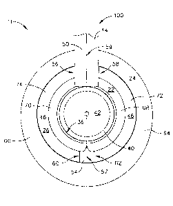
Figure 2 illustrates an end view of a nozzle assembly 11 from the perspective
of centerline 44 (shown in Figure 1). In one embodiment, nozzle assembly 11 is
a
bifurcated nozzle assembly. Nozzle assembly 11 includes nacelle 24, core cowl
22,
and outlet 46 of bypass duct 26. In the exemplary embodiment, nacelle 24 and
core
cowl 22 are coupled to wing 12 (shown in Figure 1) by pylon 14. Nozzle
assembly 11
includes a first member 50 and an opposing second member 54. Member 50 is
substantially coplanar with pylon 14 and extends through an upper portion of
nacelle
24, bypass duct 26, core cowl 22, and core nozzle 36. A conduit (not shown) is
defined within and extends through pylon 14 and member 50. The conduit allows
electrical communication for engine assembly 10 with a control system of the
aircraft.
While two members 50, 54 are shown in Figure 2, any quantity can be used with
nozzle assembly 11.
Member 54 extends through a bottom portion of nacelle 24, core nozzle 36
and core cowl 22 and is substantially coplanar with pylon 14. In some
embodiments,
member 54 includes a strut or support member. As shown in Figure 2, members
50,
54 are aligned substantially with the vertical plane defined by line 100. The
vertical
plane includes centerline 44 and, in one embodiment, is substantially
perpendicular to
-4-
CA 02609294 2007-11-01
213360
wing 12 (shown in Figure 1). Although typical installations of engine assembly
10 do
not vary from the vertical plane shown in Figure 2, other embodiments of the
present
invention exist. For example, engine assembly 10 could be mounted on a
fuselage
with a horizontal pylon.
Member 50 includes opposing sidewalls 56, 58, and member 54 includes
opposing sidewalls 60, 62. Sidewalls 56, 58, 60, 62, shown in Figure 2, extend
through bypass duct 26 toward the forward end of assembly 10 (shown in Figure
1).
Each member 50, 54 further defines a width between opposing sidewalls 56, 58
and
60, 62, respectively. In one embodiment, the width of member 54 is less than a
width
of member 50. The conduits of members 50, 54 at least partially separate
nacelle 24
and core cowl 22 into substantially symmetrical arcuate nacelle portions, 64,
66 and
arcuate cowl portions 68, 70, respectively. In some embodiments, arcuate
nacelle
portions 64, 66 of nacelle 24 are hingedly coupled to member 50. Members 50,
54
divide bypass duct 26 (not enumerated in Figure 2) forming substantially
symmetrical
duct portions, 72 and 74, respectively. Symmetrical duct portions 72, 74 may
have
any conventional configuration. In one embodiment, duct portion 72 is defined
by a
radially inner surface of arcuate nacelle portion 64, a radially outer surface
of arcuate
cowl portion 68, sidewall 58 of member 50, and sidewall 62 of member 54.
Similarly,
in one embodiment, duct portion 74 is defined by a radially inner surface of
arcuate
nacelle portion 66, a radially outer surface of arcuate cowl portion 70,
sidewall 56 of
member 50, and sidewall 60 of member 54.
Figure 3 is a side view of the exemplary nozzle assembly 11. As core cowl
22 extends downstream core cowl 22 forms a bulge portion 79 that affects the
shape
of bypass duct 26. Hingedly coupled to each sidewall 56 and 58 of first member
50 is
a flap 80, forming a set of flaps 80 (also shown in Figures 5-9). In some
embodiments, flap 80 is hingedly coupled to sidewalls 56, 58 before the apex
of bulge
portion 79. In some embodiments (as shown in Figure 3) flap 80 is hingedly
coupled
to sidewalls 56, 58 near the beginning of bulge portion 79 (i.e., toward the
forward
portion of engine assembly 10). Flap 80 extends substantially to an edge 51 of
first
member 50. In one embodiment, flap 80 has a length from about 45% to about 65%
the length of sidewalls 56, 58.
-5-
CA 02609294 2007-11-01
213360
Likewise, hingedly coupled to each sidewall 60 and 62 of second member 54
is a flap 82, forming a set of flaps 82 (also shown in Figures 5-7). In some
embodiments, flap 82 is hingedly coupled to sidewalls 60, 62 upstream from
bulge
portion 79 as shown in Figure 3. In other embodiments, flap 82 is hingedly
coupled
to sidewalls 60, 62 approximately on bulge portion 79. Flap 82 extends
substantially
to an edge 55 of second member 54. In one embodiment, flap 80 has a length
from
about 45% to about 65% the length of sidewalls 60, 62.
Although Figures 2 and 3 show two members 50, 54, other embodiments of
the present invention exist. For example, engine assembly 10 could include
four
members, two within the vertical plane and two within a horizontal plane.
Furthermore, each of the four members could include two opposing sidewalls
with
flaps.
In some embodiments, edge 51 of first member 50 extends further along the
longitudinal axis 44 than edge 55 of second member 54. Alternatively, edges
51, 55
of members 50, 54, respectively, can be substantially linear. Furthermore, as
shown
in Figures 2, 3, and 7, in one embodiment sidewalls 60, 62 of second member
meet at
the aft end of the nozzle assembly to form an end portion 57. Likewise,
sidewalls 56,
58 of first member meet at the aft end of the nozzle assembly to form an end
portion
59, which may also have at triangular shape.
Figure 4 illustrates an outline view of nozzle assembly 11 along line 4-4 of
Figure 3. Bulge portion 79 is illustrated by a first area A1, a second area
A2, and a
third area A3. First area A1 is located at an upstream position of nozzle
assembly 11;
second area A2 is positioned downstream from first area Al; and third area A3
is
positioned downstream from second area A2. In the exemplary embodiment, first
area
Aland third area A3 are less than second area A2, thus forming bulge portion
79.
Embodiments of the present invention facilitate varying airflow and/or
obstructing airflow 38 as the air flows through bypass duct 26 (or duct
portions 72,
74) and before the air is discharged (shown in Figures 5-7). In order to
reduce or
obstruct the airflow in bypass duct 26, a first set of flaps 80 and/or a
second set of
-6-
CA 02609294 2007-11-01
213360
flaps 82 are deployed to pivot (e.g., along a hinge 109) from a first
operational
position 130 to a second operational position 132 into bypass duct 26 as shown
in
Figures 8-9. In some embodiments, the set of flaps 80 and the set of flaps 82
can be
deployed independently from the other set.
Reducing the fan nozzle duct area during certain operating conditions, such
as take-off or descent, can improve fuel burn by raising the fan operating
line closer to
the peak efficiency line. In addition, reduced noise is achieved as a result
of reduced
fan wake/outlet guide vane (OGV) interaction. Moreover, opening the fan nozzle
during certain operating conditions, such as low altitude, can also reduce
noise as a
result of reduced jet velocity. The noise reduction benefit of varying the fan
nozzle
(VFN) can also be traded to further reduce fan diameter and corresponding fuel
burn.
As shown in Figure 5, in some embodiments, an upper edge of each flap 80
extends to inner surface 25 of nacelle 24 such that flap 80 can freely slide
along inner
surface 25. In other embodiments, the upper edge does not extend to inner
surface 25.
In one embodiment, flaps 80 are configured to deploy at an angle of 20 with
respect to the centerline indicated by line 100 while flaps 82 are configured
to deploy
at an angle of 100. In some embodiments, a lower edge of each flap 82 extends
to
inner surface 25 of nacelle 24 such that flap 82 can freely slide along inner
surface 25.
In other embodiments, the lower edge does not extend to inner surface 25.
Figures 6 and 7 illustrate flaps 80 and flaps 82, respectively, each in a
second
operational position 132. As illustrated in Figure 5, when the nozzle assembly
is in
operation, both sets of flaps 80, 82 pivot away from the respective sidewall
56, 58 and
60, 62 and into duct portions, 72, 74, (or along a horizontal plane defined by
line 200).
By repositioning flaps 80, 82 laterally outward, airflow 38 is reduced and/or
obstructed. Thus, when the aircraft experiences aerodynamic losses, such as
during
take-off or descent, flaps 80, 82 can be repositioned to improve the fuel burn
or
reduce the noise of nozzle assembly 11.
Deployment of flaps 80, 82 is generally accomplished by using links,
actuators, or other mechanisms, as shown in Figures 8 and 9. In one
embodiment,
-7-
CA 02609294 2007-11-01
= 213360
each flap 80, 82 is coupled by a hinge 102 to the corresponding sidewall. An
actuator
101 can be positioned within the conduit of members 50, 54, or, alternatively,
actuator
101 can be positioned within core cowl 22. As shown in Figure 8, actuator 101
includes a motor 104, an extending rod 106 coupled to motor 104 and also to a
link
110. Link 110 connects the corresponding flap to a slot 108 such that
energizing the
motors facilitates moving the flap in either an outward direction along the
horizontal
plane or an inward direction. In the exemplary embodiment, actuator 101 may be
electrically, pneumatically, or hydraulically powered to facilitate laterally
moving the
corresponding flap from first operational position 130, or stowed position, in
which
the flaps are fully retracted against the corresponding sidewalls, to the
second
operational position 132 (shown in Figure 8), wherein the flaps are laterally
extended
from the corresponding sidewalls in an outward direction.
The present invention also includes a method for operating a turbofan engine
assembly including a core gas turbine engine. The method includes varying an
operating speed of the turbofan engine assembly from a first operating speed
to a
second operating speed. The method also includes selectively positioning at
least one
of a first set of flaps and a second set of flaps to vary a throat area of a
fan nozzle duct
defined downstream from the core gas turbine engine to facilitate improving
engine
efficiency at the second operating speed. The first set of flaps and the
second set of
flaps are downstream from the core gas turbine engine and inside the fan
nozzle duct.
Described herein is a nozzle assembly that may be utilized on a variety of
turbofan gas turbine engines coupled to an aircraft. Specifically, the nozzle
assembly
having flaps positioned within the bypass fan duct, which is described herein,
improves engine performance during certain flight conditions by reducing the
bypass
duct dimensions (i.e., reducing and/or obstructing airflow), which prevents
air from
flowing through bypass duct and improves fuel burn or reduces the noise. More
specifically, the flaps while in the second operational position reduce the
available
space for airflow. The nozzle assembly is a relatively low cost and low weight
modification to the turbofan engine. By improving the engine efficiency during
take-
off and descent with use of the nozzle assembly, the engine has approximately
a 1.0%
-8-
CA 02609294 2014-04-01
better fuel-burn than other known engines with a dimension defined between the
core
cowl and the nacelle that is fixed.
An exemplary embodiment of a nozzle assembly for a gas turbine engine is
described above in detail. The assembly illustrated is not limited to the
specific
embodiments described herein, but rather, components of each assembly may be
utilized independently and separately from other components described herein.
While the invention has been described in terms of various specific
embodiments, those skilled in the art will recognize that the invention can be
practiced with modification within the scope of the invention described
herein.
-9-