Note : Les descriptions sont présentées dans la langue officielle dans laquelle elles ont été soumises.
CA 02611148 2007-12-05
WO 2006/133878 PCT/EP2006/005611
METHODS AND DEVICES FOR CONTROLLING THE IMPACT OF
SHORT CIRCUIT FAULTS ON CO-PLANAR ELECTROCHEMICAL
SENSORS
TECHNICAL FIELD
The present invention relates to analyte sensors, particularly to
electrochemical biosensors for measuring concentration of an analyte in a
fluid
sample, and more particularly to such electrochemical biosensors having co-
planar, multiple electrode systems.
BACKGROUND
In electrochemical sensors having co-planar electrode configurations,
unintentional electrical shorts between electrodes can lead to inaccurate
estimation or calculation of an amount of an analyte in a sample fluid.
Typically,
this is avoided by conducting certain failsafe system checks on the sensor,
such as
by the analytical device (meter) to which the sensor corresponds. Common
checks include measuring continuity between pairs of electrodes where
unintentional shorts can cause inaccurate measurement results. If continuity
between electrodes is detected or measured by the circuitry of the meter when
such continuity should not exist, the meter displays an error signal and the
strip is
not used.
Advances in electrochemical sensors, however, have resulted in more
complex electrode systems, often comprising three, four, five, even up to
between
ten and fifteen different electrodes. While measuring continuity between
various
pairs of electrodes in a system of two, three or even four electrodes can be
simple
and easy to implement, more complex multiple electrode systems would require
much more complex meter programming, including algorithms and/or logic
statements and rules. As a result, this simple failsafe may be less
practicable to
implement.
One particularly undesirable short circuit in a co-planar electrochemical
sensor is between a working electrode and any other electrode that may come in
CA 02611148 2007-12-05
WO 2006/133878 PCT/EP2006/005611
contact with a fluid sample applied to the sensor. Typically, the
electrochemical
response of the analyte in the fluid sample is proportional to the surface
area of
the working electrode in contact with the sample. In certain sensors, such as
capillary channel fill sensors, one or more sample sufficiency electrodes may
be
provided in a downstream location in order to detect a sufficient fill level
of the
sample in the sample channel. If one or more such sufficiency electrodes is
shorted to the working electrode, then the working electrode's surface area is
effectively increased by the amount of the sufficiency electrode in contact
with
the fluid sample. Relatively accurate estimation or calculation of the
concentration of the targeted analyte depends in part on a generally constant
value
of working electrode surface area through which the current generated from the
predetermined reaction flows. Thus, the increased working electrode surface
area
that is caused by the undesirable short circuit produces a higher
concentration
measurement result.
It is generally known, for example in a Therasense Freestyle
electrochemical sensor, to provide any other electrodes that come in contact
with
the fluid sample with generally smaller surface areas than the working
electrode.
In the past, however, this is done only in sensors comprising a facing (or
opposing) electrode configuration. Generally, the intent of such a design is
to
provide a large counter electrode that does not limit the current induced by
the
electrochemical reaction at the working electrode, and to assure that the
sample
chamber of the electrochemical sensor is completely filled before a
measurement
sequence is initiated. Incidentally, it is as a result of the facing
configuration that
there is a reduced likelihood of undesirable shorts, and the probability of a
harmful short circuit is much less in the facing configuration.
SUMMARY OF THE INVENTION
It is against the above background that the present invention provides
certain unobvious advantages and advancements over the prior art. In
particular,
the inventor has recognized a need for improvements in methods and devices for
controlling the impact of short circuit faults on co-planar electrochemical
sensors.
2
CA 02611148 2007-12-05
WO 2006/133878 PCT/EP2006/005611
Although the present invention is not limited to specific advantages or
functionality, it is noted that the present invention provides various
embodiments
for limiting the effect on the analyte measurement of short circuit faults
between a
working electrode and any other electrode that is intended, by design, to come
in
contact with the sample fluid. Two exemplary ways of doing this are disclosed
herein, namely providing an electrode configuration that induces an otherwise
undetected short circuit between one or more pairs of electrodes which the
system
is already configured to detect, and minimizing the surface area of such other
electrodes that contact sample fluid, in relation to the surface area of the
working
electrode.
In accordance with one embodiment of the present invention, an
electrochemical sensor is provided for measuring the concentration of an
analyte
in a sample fluid. The sensor is adapted for being received by and
electrically
connected to a meter, and it comprises a co-planar electrode system having a
working electrode, a plurality of other electrodes and a sample receiving
area.
First and second electrodes of such other electrodes are configured each to be
electrically isolated from the other and from the working electrode. The first
electrode comprises a distal end at least a portion of which is exposed within
the
sample receiving area. The second electrode has at least one end configured to
extend substantially between the working electrode and the first electrode
proximate the one end. As a result, any undesired electrical connectivity
between
the working electrode and the first electrode must also result in electrical
connectivity between the first electrode and the second electrode proximate
the
one end.
In accordance with other embodiments, the meter is configured to verify
the electrical isolation between the working electrode and the second
electrode
and between the first electrode and the second electrode when the sensor is
electrically connected to the meter, but it is not configured to verify the
electrical
isolation between the working electrode and the first electrode.
In accordance with yet other embodiments, a method is provided for
indirectly verifying electrical isolation between non-adjacent electrodes of
an
3
CA 02611148 2007-12-05
WO 2006/133878 PCT/EP2006/005611
electrochemical sensor having a co-planar electrode system. The method
comprises the steps of providing a working electrode and at least first and
second
electrodes on the sensor, at least a portion of the working electrode and the
first
electrode being exposed in a sample receiving area of the sensor, the second
electrode being provided having at least one end configured to extend
substantially between the working electrode and the first electrode proximate
the
one end, each of the first electrode, second electrode and working electrode
being
intended to be electrically isolated each from the other; inserting the sensor
into a
meter configured to receive and electrically connect with the sensor; using
the
meter to detect or measure electrical connectivity between the working
electrode
and the second electrode; using the meter to detect or measure electrical
connectivity between the first electrode and the second electrode; and
displaying
an error message on the meter if electrical connectivity is detected or
measured
between the working electrode and the second electrode or between the first
electrode and the second electrode. With this method, any undesired electrical
connectivity between the first electrode and the working electrode must also
result
in electrical connectivity between the first electrode and the second
electrode
proximate the one end of the second electrode.
In accordance with yet other embodiments, an electrochemical sensor is
provided for measuring concentration of an analyte in a sample fluid. The
sensor
is adapted for being received and electrically connected to a meter, the
sensor
comprising a co-planar electrode system having a sample receiving area, a
working electrode at least a portion of which is exposed within the receiving
area,
and at least one other electrode, the at least one other electrode being
configured
to be electrically isolated from the working electrode and comprising a distal
end
at least a portion of which is exposed within the sample receiving area, the
surface
area of the exposed portion of the at least one other electrode being no more
than
about 50% of the surface area of the exposed portion of the working electrode.
In accordance with yet other embodiments, a method is provided for
controlling the affect of a short circuit between critically matched
electrodes in an
electrochemical sensor having a co-planar electrode system. The method
4
CA 02611148 2011-01-13
comprises the steps of providing an electrochemical sensor having a sample
receiving area,
a working electrode having at least a portion exposed within the sample
receiving area, and
at least one other electrode intended to be electrically isolated from the
working electrode
and comprising a distal end having at least a portion thereof exposed within
the sample
receiving area; providing the at least one other electrode with a surface area
of the exposed
portion of the distal end thereof being no more than about 50% of the surface
area of the
exposed portion of the working electrode.
In accordance with yet other embodiments, an electrochemical sensor for
measuring
concentration of an analyte in a sample fluid, comprising a co-planar
electrode system and a
sample receiving area, the electrode system comprising a plurality of
electrodes each having
a distal end at least partially exposed within the sample receiving area and a
proximal end
comprising a contact pad, each distal end being connected to a corresponding
contact pad by
a trace lead extending therebetween, each contact pad being configured for
electrical
connection to a meter configured for use with the electrochemical sensor;
wherein first and
second electrodes of the plurality of electrodes have respective contact pads
laterally spaced
apart with a space between them, a third electrode of the plurality of
electrodes being
located substantially entirely between the first and second electrodes, the
contact pad of the
third electrode being located entirely between the respective trace leads of
the first and
second electrodes, the third electrode further comprising a terminal extension
extending
from the contact pad thereof into the space between the contact pads of the
first and second
electrodes.
These and other features and advantages of the present invention will be more
fully
understood from the following detailed description of the invention taken
together with the
accompanying claims. It is noted that the scope of the claims is defined by
the recitations
therein and not by the specific discussion of features and advantages set
forth in the present
description.
5
CA 02611148 2011-01-13
BRIEF DESCRIPTION OF THE DRAWINGS
The following detailed description of the embodiments of the present invention
can
be best understood when read in conjunction with the following drawings, where
like
structure is indicated with like reference numerals and in which:
Figure 1 is a top view of a prior art embodiment of the insertion end of a
sensor
having a complex multiple electrode system.
Figure 2 is a top view of the insertion end of a sensor according to an
alternative
embodiment of the present invention providing at least one electrode with a
size and/or
shape configured to induce a detectable short circuit between adjacent
electrodes in order to
indicate a short circuit between non-adjacent electrodes.
Figure 3 is a top view of the sample-channel end of a sensor according to
another
alternative embodiment of the present invention providing at least one
electrode with a size
and/or shape configured to induce a detectable short circuit between
critically matched
electrodes in order to indicate a short circuit between non-adjacent
electrodes.
5a
CA 02611148 2007-12-05
WO 2006/133878 PCT/EP2006/005611
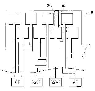
Figure 4 is a top view of a prior art embodiment of the sample-channel end
of a sensor having a complex multiple electrode system.
Figure 5 is a top view of the sample-channel end of a sensor according to
one embodiment of the present invention providing sample-sufficiency
electrodes
of significantly reduced surface area exposed in the sample channel.
Figure 6 is a top view of the sample-channel end of a sensor according to
another embodiment of the present invention providing sample-sufficiency
electrodes of significantly reduced surface area exposed in the sample
channel.
Figure 7 is a top view of the sample-channel end of a sensor according to
yet another embodiment of the present invention providing sample-sufficiency
electrodes of significantly reduced surface area exposed in the sample
channel.
Skilled artisans appreciate that elements in the figures are illustrated for
simplicity and clarity and have not necessarily been drawn to scale. For
example,
the dimensions of some of the elements in the figures may be exaggerated
relative
to other elements to help improve understanding of the embodiment(s) of the
present invention.
DETAILED DESCRIPTION OF THE INVENTION
In order that the invention may be more readily understood, reference is
made to the following examples, which are intended to illustrate the
invention, but
not limit the scope thereof.
It is noted that terms like "preferably", "commonly", and "typically" are
not utilized herein to limit the scope of the claimed invention or to imply
that
certain features are critical, essential, or even important to the structure
or
function of the claimed invention. Rather, these terms are merely intended to
highlight alternative or additional features that may or may not be utilized
in a
particular embodiment of the present invention.
For the purposes of describing and defining the present invention it is
noted that the term "substantially" is utilized herein to represent the
inherent
degree of uncertainty that may be attributed to any quantitative comparison,
6
CA 02611148 2007-12-05
WO 2006/133878 PCT/EP2006/005611
value, measurement, or other representation. The term "substantially" is also
utilized herein to represent the degree by which a quantitative representation
may
vary from a stated reference without resulting in a change in the basic
function of
the subject matter at issue.
Referring now to Figs. 1-3, electrochemical sensors 10 may be provided
with complex electrode systems. For example, from Fig. 1, each of the counter
and working electrodes 12, 14 (hereinafter referred to as "CE" and "WE"
respectively) in one embodiment of such a sensor comprise dual trace leads 16
with independent contact pads 18 for electrically connecting the electrodes
12, 14
to a meter (not shown). Sample sufficiency electrodes 20 may also be provided,
for example the sample sufficiency counter electrode 22 and sample sufficiency
working electrode 24 (hereinafter referred to as "SSCE" and "SSWE"
respectively). Furthermore, additional, auxiliary trace leads 26 and their
respective contacts 28 may be provided in electrical connection with the trace
lead
16 for one or more of the electrodes 12, 14 provided on the sensor 10. The
purposes and configurations for each of these components are known to
Applicants, but are not relevant to the current disclosure. As a result, no
further
discussion regarding the specific configurations and purposes of the various
electrode components will be described herein, except as such may relate to
the
present invention.
Complex electrode systems provided on a relatively small sensor 10 give
rise to certain space constraints. For example, as shown in Figure 1, the
contact
pads 18, 28 in one embodiment are staggered in at least two lateral rows. Each
laterally-adjacent contact pad in this staggered configuration pertains to
every
other trace lead provided in the electrode system; thus, adjacent trace leads
do not
extend into laterally-adjacent contact pads. For example, the trace lead 16
for the
WE 14 is adjacent the trace lead 16 for the SSWE 24, but the contact pad 18
for
the WE 14 is laterally adjacent the contact pad 18 for the SSCE 22 whereas the
contact pad 18 for the SSWE 24 is laterally adjacent the trace leads 16 for
the
SSCE 22 on one side and for the WE 12 on the other.
7
CA 02611148 2007-12-05
WO 2006/133878 PCT/EP2006/005611
Except for the connection of the auxiliary trace leads 26 according to a
particular electrode system design (for example, as shown in Figure 1) and
except
for the dual trace leads of the WE and CE 14, 12, the components of the
electrode
system are intended to be generally electrically isolated from each other. It
is a
familiar failsafe to ensure electrical isolation in such systems by using a
meter
into which the sensor is inserted to apply an electrical potential or other
electrical
effect at the contact pads of a pair of such isolated electrodes, and
detecting or
measuring electrical effects indicative of electrical connectivity, such as
current,
potential or resistance, across the critically paired electrodes. Electrical
isolation
can be absolute (e.g. infinite resistance or zero current), or can be
subjectively
predetermined (e.g. a threshold minimum resistance or threshold maximum
current). (For purposes of this disclosure and the scope of the claims, the
term
"measuring" is intended and used to refer to any detection (as against
absolute
isolation) of an electrical effect indicative of connectivity as well as any
quantification (for comparison against a predetermined threshold) thereof
Whether electrical isolation is desired to be absolute or subject to an
allowable
threshold is within the discretion of the person practicing the invention and
is not
a limitation of the scope of the invention.) If, after applying a potential or
other
electrical effect, electrical isolation cannot be confirmed or verified, an
error
message is provided and the sensor is not permitted to be used.
Due to the complexity of certain electrode systems, such as in Fig. 1, or
due to the fixed design and methodology of a meter with which such an
electrode
system is intended to be used, it may be difficult or cost-ineffective to
provide or
modify a meter to perform this failsafe on each and every pair of electrode
contact
pads that are intended to be electrically isolated. Furthermore, the
interposition of
certain components of the system, such as the contact pad and trace lead of
the
SSWE 24 being located generally between the trace leads of the SSCE 22 and the
WE 14, makes undesirable shorts unlikely to be missed, provided that the
electrodes with adjacent lead traces 16 are checked against each other, such
as the
SSCE 22 and SSWE 24, or the SSWE 24 and the WE 14. Thus, the meter-sensor
8
CA 02611148 2007-12-05
WO 2006/133878 PCT/EP2006/005611
system may rely on certain strategic failsafe checks to account for all
possible
failsafe modes.
Although not highly likely, there remains the possibility that a short can
occur between electrodes which are not checked in this way because their
relative
locations make such shorts difficult. For example, for the sensor of Fig. 1,
SSCE
22 and WE 14 may be left unchecked due to the interposition of the contact pad
and trace lead of the SSWE 24, the SSWE 24 being separately checked by the
meter for isolation from the SSCE 22 and the WE 14. However, the space 30
above the contact pad for the SSWE 24 and between the contact pads for the
SSCE 22 and WE 14 is left open. Due to any number of reasons, such as
manufacturing defects, it remains possible that the SSCE 22 and WE 14 could be
shorted together across this open space 30. Similarly, an open trail 32 can be
identified at the sample channel end 34 of the sensor 10 between the SSCE 22
and
the trace lead of the WE 14.
Despite the unlikelihood of an undesired short circuit occurring across
either of these locations 30, 32, the fact that it is not impossible may
present
significant problems with the accuracy of the analyte measurement results
provided by the meter. As discussed above, if the WE 14 is shorted to another
electrode that is exposed in the sample channel 36 such that such other
electrode
comes into contact with the sample fluid (not shown), the practical effect is
that
the surface area of the WE 14 is increased by the amount of exposed surface
area
of the other electrode. The measured current increases accordingly, which
provides a high bias to calculations that are dependent upon a constant
surface
area for the WE 14.
From the configuration of the sensor of Fig. 1, this could occur if either of
the SSWE 24 or SSCE 22 are shorted to any part of the WE 14 because the SSWE
24 and SSCE 22 are included in the sample channel 36 for purposes of the
sample
sufficiency detection functionality. To maintain a relatively simple meter set
up,
the meter failsafe checks may check SSWE 24 against SSCE 22 (necessary in
order for the sample sufficiency functionality to work properly) and SSWE 24
against WE 14 (because they are mostly adjacent and more likely to face
9
CA 02611148 2007-12-05
WO 2006/133878 PCT/EP2006/005611
undesirable shorting). As pointed out above, however, there remains the slight
possibility of shorting the SSCE 22 to the WE 14 across the open space 30 at
the
contact pad end 38 and the open trail 32 at the sample channel end 34.
Referring now to Figs. 2 and 3, the size and/or shape of certain aspects of
the electrodes may be configured to prevent this possibility. From Fig. 2, the
contact pad of the SSWE 24 can be provided with an extension 40 toward the
contact pad end 38 of the sensor 10 to interrupt the open space 30. As a
result,
any cause of a short across the open area 30 likely induces a short between
the
SSWE 24 and the WE 14, for which a failsafe is provided, due to the space
constraints. Even if the short would not have otherwise spanned across the
entire
open space 30, the extension 40 from the contact pad of the SSWE 24 ensures
that
any possible short in that space 30 also will at least cause a short either
between
the SSCE 22 and SSWE 24 or between the SSWE 24 and WE 14, if not both.
Similarly, from Fig. 3, the open trail 32 may be interrupted by a portion 42
of the CE extending into the trail. As a result, any cause of a short that
would
otherwise course over the open trail 32 will induce a short between the CE 12
and
WE 14, for which a failsafe is already provided.
As indicated, the result of undesirable shorts between the WE 14 and other
electrodes that are exposed by design in the sample channel 36 is a high bias
to
the measurement result caused by an increased effective surface area for the
WE
14. Referring now to Figs. 4-7, an alternative embodiment of the present
invention at least minimizes the resulting high bias to an acceptable level.
Figure
4 shows a prior art configuration of the sample channel end 34 of a sensor 10,
in
which the SSCE 22 and SSWE 24 are exposed in the sample channel 36 for
purposes of detecting fluid sample (not shown) filling the channel up to that
point,
downstream from the portions of the CE 12 and WE 14 exposed in the channel
36. In Fig. 4, the exposed surface area of each of the SSCE 22 and SSWE 24 is
less than the exposed surface area of the WE 14, but significantly more than
about
50% of the exposed WE 14. A short between the WE 14 and any of the SSCE 22
and SSWE 24 would thus increase the effective surface area by at least about
60-
70% or more.
CA 02611148 2007-12-05
WO 2006/133878 PCT/EP2006/005611
To minimize the undesirable effects of this increase, embodiments of the
present invention limit the exposed surface area of the SSCE 22 and SSWE 24 in
the sample channel 36 to no more than about 50% of the exposed surface area of
the WE 14 in the sample channel 36. In other embodiments, the exposed surface
area of the SSCE 22 and SSWE 24 in the sample channel 36 is limited to no more
than about 10% of the exposed surface area of the WE 14 in the sample channel
36.
Various configurations for reduced SSWE 24 and SSCE 22 surface area
can be implemented, including various sizes and/or shapes for the exposed
portions thereof. For example, in Fig. 5 (not shown to scale), the trace leads
for
the SSCE 22 and SSWE 24 extend down the sensor 10 so as to straddle the
sample channel 36 and extend therein perpendicularly from opposite sides so
that
they are laterally aligned. In such embodiments, the electrodes 22, 24 extend
only
partially into the channel 36 in order to minimized exposed surface area
within
the sample channel.
In the embodiment of Fig. 6 (not shown to scale), the trace leads for the
SSCE 22 and SSWE 24 extend down the sensor 10 similarly straddling the
channel 36, and extend therein perpendicularly, but offset linearly so that
each
electrode 22, 24 may extend substantially across the channel 36. In such
embodiments, the electrodes 22, 24 are typically narrower (thinner) in order
to
minimize exposed surface area within the sample channel 36.
In the embodiment of Fig. 7 (not shown to scale), the trace leads of the
SSCE 22 and SSWE 24 extend down the sensor 10 generally directly into the
proximal end 44 of the sample channel 36 to a point short of the CE 12. In
such
embodiments, the electrodes 22, 24 are again narrower (thinner) in order to
minimize exposed surface area within the sample channel 36.
In addition to the foregoing embodiments pertaining to electrode
structures on the sensors, the present invention further sets forth
embodiments of
methods relating to the use of such sensors with a meter configured for
receiving
and electrically connecting with such sensors. Steps relating to the methods
are
disclosed in this specification and recited in the claims appended hereto.
11
CA 02611148 2011-01-13
Having described the invention in detail and by reference to specific
embodiments
thereof, it will be apparent that modifications and variations are possible.
More specifically,
although some aspects of the present invention may be described herein as
being preferred
or particularly advantageous, it is contemplated that the present invention is
not necessarily
limited to those aspects of the invention.
12