Note : Les descriptions sont présentées dans la langue officielle dans laquelle elles ont été soumises.
CA 02612688 2007-12-18
WO 2007/002339 PCT/US2006/024389
OSTEOGRAFT TREATMENT TO PROMOTE OSTEOINDUCTION AND
OSTEOGRAFT INCORPORATION
Field of the Invention
The present invention relates generally to bone grafts and methods for
preparing
graft materials. The invention also relates to implants, for example, implants
suitable for
insertion into the intervertebral space and to implants suitable for use in
orthopedic
applications.
Background of the Invention
Bone grafts are used to repair bone that has been damaged by disease, trauma,
or
surgery. Grafts may be utilized when healing is impaired in the presence of
certain drugs
or in disease states such as diabetes, when a large amount of bone or disc
material is
removed during surgery, or when bone fusion is needed to create stability. In
some types
of spinal fusion, for example, bone grafts are used to replace the cushioning
disc material
between the vertebrae.
Bone graft (osteograft) materials may include both synthetic and natural bone.
Natural bone may be taken from the graft recipient (autograft) or may be taken
from
another source (allograft), such as a cadaver, or (xenograft), such as bovine.
Autograft has
advantages such as decreased immunogenicity and greater osteoinductive
potential, but
there can also be problems with donor site morbidity and limited supply of
suitable bone
for grafting. On the other hand, allografft is available in greater supply and
can be stored
for years--but is less osteoinductive.
Osteoconduction and osteoinduction both contribute to bone formation. A graft
material is osteoconductive if it provides a structural framework or
microscopic and
macroscopic scaffolding for cells and cellular materials that are involved in
bone
formation (e.g., osteoclasts, osteoblasts, vasculature, mesenchymal cells).
Osteoinductive
material, on the other hand, stimulates differentiation of host mesenchymal
cells into
chondroblasts and osteoblasts. Natural bone allograft materials can comprise
either
cortical or cancellous bone. A distinguishing feature of cancellous bone is
its high level of
porosity relative to that of cortical bone, providing more free surfaces and
more of the
cellular constituents that are retained on these surfaces. It provides both an
osteoinductive
CA 02612688 2007-12-18
WO 2007/002339 PCT/US2006/024389
2
and osteoconductive graft material, but generally does not have significant
load-bearing
capacity. Optimal enhancement of bone formation is generally thought to
require a
minimum threshold quantity of cancellous bone, however. Cortical (compact)
bone has
greater strength or load-bearing capacity than cancellous bone, but is less
osteoconductive.
In humans for example, only twenty percent of large cortical allografts are
completely
incorporated at five years. Delayed or incomplete incorporation may allow
micromotion,
leading to host bone resorption around the allograft. A more optimal bone
graft material
would combine significant load-bearing capacity with both osteoinductive and
osteoconductive properties, and much effort has been directed toward
developing such a
graft material.
Some allografts comprise mammalian cadaver bone treated to remove all soft
tissue, including marrow and blood, and then textured to form a multiplicity
of holes of
selected size, spacing, and depth. The textured bone section is then immersed
and
demineralized, preferably in a dilute acid bath. Demineralizing the bone
exposes
osteoinductive factors, but extensive demineralization of bone also decreases
its
mechanical strength.
Allograft has also been formed of organic bone matrix with perforations that
extend from one surface, through the matrix, to the other surface to provide
continuous
channels between opposite surfaces. The organic bone matrix is produced by
partial or
complete demineralization of natural bone. Although the perforations increase
the
scaffolding potential of the graft material and may be filled with
osteoinductive material as
well, perforating organic bone matrix through the entire diameter of the graft
decreases its
load-bearing capacity.
Partially-demineralized cortical bone constructs may be surface-demineralized
to
prepare the graft to be soaked in bone growth-promoting substances such as
bone
morphogenetic protein (BMP). Although this design allows greater exposure of
the
surrounding tissue to growth-promoting factors, the surface demineralization
necessary to
adhere a substantial amount of growth-promoting factors to the graft material
decreases
the allograft's mechanical strength. Demineralized bone allograft materials
are
commercially available and widely used, since demineralization exposes
underlying BMP
at the surface of the allograft, but these materials lack the mechanical
strength necessary to
provide an optimal bone graft material and the treatment does not result in
exposure of
enough BMP to be of significant benefit in promoting osteoinduction.
CA 02612688 2007-12-18
WO 2007/002339 PCT/US2006/024389
3
What is needed is a bone graft material that combines the osteoinductive and
osteoconductive properties of cancellous bone with the load-bearing capacity
provided by
cortical allograft materials.
Summary of the Invention
The invention provides a bone graft material ("osteograft") that retains
bioactive
agents to facilitate host bone incorporation while maintaining load-bearing
capacity, the
osteograft having at least one pit in at least one surface of the osteograft,
and at least one
plug inserted into the pit. The plug may be formed of one or more porous
materials. In
one embodiment, the plug can comprise cancellous bone. In other embodiments,
plugs
may be formed of a variety of natural or synthetic materials, or a combination
of both.
The invention also provides a method of constructing an osteograft that
retains
bioactive agents, the method comprising forming at least one pit in at least
one surface of
an osteograft, and forming a plug to insert into the pit.
The invention also provides a method for decreasing incorporation time for
implanted osteograft, by forming at least one pit in at least one surface of
the osteograft
and inserting a biologic or non-biologic plug into the pit to absorb and
retain the bioactive
agent within the pit, forming the pit to have a shape that increases retention
of the
bioactive agent through hydrostatic attraction, or a combination of both.
Bioactive agents may also be retained by an osteograft described by the
present
invention when one or more pits are formed in a shape that provides increased
hydrostatic
attraction of the fluid retained within the pit. Plugs may or may not be
inserted into such
pits, since the shape of the pit promotes fluid retention whether a plug is
present or not.
Also provided by the invention are bone graft systems or kits comprising
osteografts having pits formed in one or more surfaces of the osteograft, and
plugs for
insertion into the pits or plugs already inserted into one or more pits. Such
kits may also
comprise aliquots of bioactive agents suitable for application to the
osteograft pits.
Brief Description of the Drawings
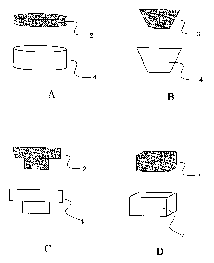
FIG. 1 illustrates lateral cross-sectional views of pits 4 and corresponding
plugs 2
of complementary geometric shape that may be provided in an osteograft as
described by
the present invention.
CA 02612688 2007-12-18
WO 2007/002339 PCT/US2006/024389
4
FIG. 2 illustrates side views pit shapes that retain fluid by hydrostatic
attraction of
fluid within the pit. Such pits typically, but not necessarily, have an
opening diameter 6
that is less than the base diameter 8 of the pit.
FIG. 3 illustrates cross-sectional views of alternate embodiments of pit 2 and
plug
4 combinations in an osteograft 12 according to the invention. In 3a, a pit 4
is
substantially filled by plug 2. In 3b, a reservoir 10 is created between plug
2 and pit 4
when plug 2 is placed into pit 4 so that it fits within the opening of the pit
but does not fill
the pit. Rather, placement of the plug in the opening leaves a space for fluid
between the
plug and the bottom and side(s) of the pit, forming the reservoir. In 3c, a
plug 2 is placed
into a pit 4 of similar geometry so that a reservoir is formed.
FIG. 4 is a cross-sectional view of an embodiment of an osteograft 12 as
described
by the invention wherein at least one internal surface of a pit 4 is
demineralized to form a
zone of demineralization 14.
FIG. 5 is a graph illustrating the relationship between pit height, the
diameter of
the pit opening, and the surface tension of selected fluids (saline, water,
bone marrow
aspirate (BMA), bone morphogenetic protein (BMP-2)) within the pit. For a
given fluid,
the surface tension will hold the fluid in the pit when oriented downward if
the
diameter/height ratio of the pit is below the curve.
FIG. 6 is a graph indicting the Diameter to Cavity Height Relationship for
saline,
Z 0 water, BMA and BMP-2.
FIG. 7A is an illustration of a method for forming a pit 4 in an osteograft 12
by
drilling or grinding with an implement such as a ball end mill 16. As the
arrows indicate,
the implement may be forced downward longitudinally as it rotates laterally. A
variety of
?5 shapes can be achieved using such an implement and method. One such shape
is shown in
FIG. 7B.
FIG. 8A is a cross-section of an osteograft 12 of the invention with pits 4
formed
in two surfaces. FIG. 8b is an inverted cross-section of a pit 4 as found in
an osteograft 12
of the invention, fluid in the pit 2 forming a column 18 directly above the
opening 6 of the
30 pit.
FIG. 9 is a bar graph which is measuring Shear Strength (N/mm2) of an
Untreated
Allograft, an Untreated Allograft and rhBMP-2, an Allograft with Straight Pits
and and
Allograft with Straight Pits with rhBMP-2..
CA 02612688 2007-12-18
WO 2007/002339 PCT/US2006/024389
FIG. 10 is a bar graph showing the percent change of sheer strength of the
Allograft with Straight Pits and the Allograft with Straight Pits with rhBMP-2
as
compared to an Untreated Allograft.
Detailed Description
5 The inventors have discovered that cortical allograft or synthetic bone
material can
be utilized to form a bone graft material ("osteograft") that combines
osteoinductive and
osteoconductive properties with load-bearing capacity. An osteograft of the
invention
incorporates the beneficial properties of cancellous bone but retains the
superior load-
bearing capacity of cortical bone. As used herein, "osteograft" encompasses
natural bone
allograft such as cortical bone, synthetic materials used to form bone graft
substitutes, and
combinations of natural and synthetic materials. Synthetic materials suitable
for allograft
formation include, for example, coralline hydroxyapatite, tricalcium phosphate
and
hydroxyapatite, calcium sulfate, Bioglass granules (Novabone Products,
Alachua,
Florida), aipha-tricalcium phosphates, calcium carbonate, and a variety of
ceramic
materials. The invention provides an osteograft that provides faster, more
uniform fusion,
a more uniform outcome, and the potential for less pain, than that provided by
allograft or
synthetic graft materials currently in orthopedic use. An osteograft of the
invention may
comprise allograft or xenograft material.
An osteograft as described by the invention has load-bearing properties
provided
by natural allograft or synthetic bone in conjunction with osteoinductive
properties
provided by pits formed in the osteograft to not only increase surface area
but also to make
bioactive agents available at the graft/host junction. Bioactive agents may be
osteoinductive factors. These agents are retained within the osteograft pits
by plugs
inserted into the pits or by forming the pits to increase fluid retention
through hydrostatic
force within the pit, or a combination of both.
The invention also provides a method for retaining a bioactive agent in an
implanted osteograft. "A bioactive agent," as used herein, encompasses one or
a
combination of two or more bioactive factors such as, for example, bone-growth
promoting cellular factors such as bone morphogenetic protein (BMP), LIM
mineralization protein (LMP), particulate bone, CHRYSALIN , bone marrow
aspirate,
concentrated bone marrow aspirate, and demineralized bone matrix (DBM), growth
differentiation factor, such as GDF-5, anti-inflammatory factors such as TNF
inhibitors,
CA 02612688 2007-12-18
WO 2007/002339 PCT/US2006/024389
6
anti-infective agents, mesenchymal cells, hematopoietic cells, osteogenic
precursor cells,
or various types of stem cells, pain relief agents, or a combination thereof.
Non-polymeric
hematopoietic cell clots, for example, such as those described by Pascher, et
al., U.S.
Patent Application Number 10/457,000 (Publication No. 20040037819) may be
useful as
bioactive agents, and for delivery of bioactive agents, in an osteografi of
the invention. A
variety of bioactive agents known to those of skill in the art are suitable
for use in the
osteograft and method of the present invention.
Bioactive agents can be provided in modified release form such as, for
example,
polymers in formulation with one or more bioactive agents to control the rate
of
dissolution or diffusion of the agent, functional coatings to delay
dissolution or release of
bioactive agents, or other similar compositions such as modified-release
microspheres
known to those of skill in the art. References such as the Handbook on
Pharmaceutical
Controlled Release Technology, D.L. Wise (ed.), Marcel Dekker, Inc., New York
(2000)
provide examples and instruction for formulating modified release compositions
appropriate for use in the present invention.
The invention provides an osteograft and method that increase the amount of at
least one bioactive agent, such as BMP, available at the osteograft/host bone
junction and
thereby decrease the time required for osteograft incorporation. Allografts
inserted
without the addition of BMP generally take 12 to 18 months for incorporation.
When
BMP is available at the junction between the allograft and the host bone
endplates, the
time for incorporation can be cut by one-third to one-half. Faster
incorporation and fusion
of bone in spine fusion can decrease undesirable motion along the
allograft/host end plate
interface.
As used herein, a "pit" is a defined space formed beneath at least one surface
of an
osteograft or an area sunken or depressed below the adjacent osteograft
surface, and the
term can be used interchangeably with the terms "depression," "cavity,"
"indentation,"
"hollow," or "hole." Pits may be formed in various dimensions and shapes, such
as about
2 mm in diameter and about 3 mm in depth, or about 1 mm in diameter and about
1 mm in
depth. Generally, it may be beneficial to form a pit so that the ratio of
depth to diameter is
at least about 2 to 1 to promote retention of fluid within the pit. Pits may
also be formed
so that the opening is wider than the base to more easily insert plugs, or so
that the base is
wider than the opening to increase retention of the plug or retention of fluid
within the pit
through hydrostatic forces. Dimensions chosen for depth and diameter of the
pits should
CA 02612688 2007-12-18
WO 2007/002339 PCT/US2006/024389
7
increase exposure to osteoinductive factors at the surface of the allograft,
while
maintaining the structural integrity and load-bearing capacity of the
allograft.
Pits can be formed in an osteograft as it is formed of synthetic materials.
The
desired pattern and shape of pits can also be formed in an osteograft "blank"
formed of
natural allograft or synthetic material. Pits may be formed by means known to
those of
skill in the art such as, for example, laser drilling, mechanical drilling,
computer-
numerically-controlled (CNC) milling, and press-forming. Pits can be formed in
uniform
or non-uniform cross-sectional shape, can be circular, semi-circular, conical,
rectangular,
or cylindrical with a conical portion (particularly at the base), for example.
Pits may be
axisymetric or asymmetric.
Appropriate shape(s) for pits in a particular osteograft can be determined by
those
of skill in the art. Pit density and diameter, as well as pit depth, should be
chosen
according to the desired location and requisite load-bearing capacity of the
allograft. The
inventors recommend, for example, that the diameter of individual pits be
minimized in
osteografts needed for heavier load-bearing uses. Larger pits (in terms of
depth and
diameter), can be utilized at the surfaces that will interface with the host
bone, while
smaller pits can be located elsewhere in the osteograft. Structural integrity
and load-
bearing capacity of the osteograft should be considered when determining the
depth of the
pits. It is generally not desirable to utilize pits that traverse the entire
diameter of (i.e., "run
through") the osteograft or have such depth that they may significantly
decrease the load-
bearing capacity of the osteograft.
Pits are especially beneficial on the surfaces where the host bone and
osteograft
make contact, since one goal of osteograft implantation is that the host bone
grows into the
pits. As the host bone expands into the pits, osteoblasts add new bone while
osteoclasts
remove the osteograft bone material. Through "creeping substitution," the
osteograft
becomes incorporated and eventually replaced by host bone tissue.
The interior of one or more pits may be treated to demineralize the interior
surface
of the pit, as shown in Fig. 4, which illustrates a pit 4 having a zone of
demineralization 14
along its internal surface(s). Pits can be demineralized, for example, by
applying
hydrochloric acid (e.g., 0.6 M HCl) within them and then rinsing the acid from
the pit. The
extent of demineralization of pits should be limited so that it is not so
significant as to
affect the structural integrity and load-bearing capacity of the allograft.
CA 02612688 2007-12-18
WO 2007/002339 PCT/US2006/024389
8
In one embodiment of the invention plugs formed of porous material can be
placed
within one or more pits formed in an osteograft. "Porous" plugs are plugs
having
sufficient permeability or porosity to absorb or adsorb at least a minimal
quantity of fluid,
paste, or putty comprising at least one bioactive substance. As shown in FIG.
lA-FIG.
1D, pits 4 of various geometries can be formed in an osteograft of the present
invention
and can have plugs 2 of complementary geometry, as shown, inserted therein. In
one
embodiment of the invention, a plug 2 essentially fills a pit 4 (FIG. 3A). In
another
embodiment, a plug can be placed into a pit so that a space is formed between
the bottom
of the plug and the bottom of the pit to create a reservoir 10 between the
plug and the
bottom and side(s) of the pit, as shown in FIG. 3B and FIG. 3C. Plugs may be
complementary in shape to a corresponding pit, may be irregular in shape, may
be formed
in the shape of a wedge, cylinder, or ellipse, for exainple, and may have
curved, linear, or
other surfaces that are appropriate for the design of the individual type of
plug. One plug
or more than one plug may be placed within any one pit.
Plugs can be made of biologic or non-biologic material, including porous
synthetic
materials, cancellous bone, porous collagen, gelatin, hyaluronic acid,
cellulose, starch,
calcium phosphate, or a combination thereof. Plugs may be formed from
autograft,
allograft or xenograft material.
Plugs may be placed into liquids comprising bioactive agents so that they will
absorb such agents prior to being placed into the osteograft pits, or the
osteograft may be
placed in one or more bioactive agents after one or more plugs are placed in
pits. Pits can
be filled with bioactive agents prior to final assembly of the osteograft, or
may be filled in
the operating room prior to surgical implantation of the osteograft. Plugs can
be used to
provide a porous seal for a reservoir provided by the pit (FIG. 3B and 3C), or
can fill the
pit (FIG. 3A) to retain a bioactive agent. Plugs may be inserted into pits
without a
bioactive agent having been first applied, or a bioactive agent can be applied
prior to
inserting a plug into a pit. Bioactive agents may be applied to plugs by
soaking the plugs
in the agent, using a syringe or other applicator so that the bioactive agent
can be absorbed
by, or adsorbed to, the plug(s) before or after they are placed into pits, or
other means
known to those of skill in the art. Pastes, putties, or other compositions may
also be
spread along the allograft so that they fill a pit prior to or after insertion
of one or more
plugs.
CA 02612688 2007-12-18
WO 2007/002339 PCT/US2006/024389
9
Plugs may be inserted so that the top of the plug is flush with the surface of
the
allograft or so that it is depressed below the allograft surface.
In one embodiment of the invention, pits are formed so that the shape of a pit
decreases the fluid force on the pit opening and increases retention of fluid
placed within
the pit. Such pits retain bioactive agents within them with or without plugs.
Fig. 2
illustrates pits having shapes that increase fluid retention. Such pits can be
created by
those of skill in the art using various means such as, for example, a ball end
mill of
appropriate size. These pits generally have an opening with a diameter 10 that
is less than
the diameter of the base of the pit 12. When inverted so that the force of
gravity pushes
the fluid within the column against the pit opening, the force applied is
based upon the
diameter of the column of fluid directly over the opening, not upon the entire
mass of fluid
within the pit.
Pit shape and dimensions to increase hydrostatic pressure and surface tension
within the pit can be determined by those of skill in the art, keeping in mind
that if the net
weight of fluid above the entrance to the pit is less than the fluid tension
force acting at the
pit entrance, the fluid will generally be retained inside the pit when the pit
is inverted. The
surface tension and density of a fluid having unknown surface tension and
density can be
experimentally determined by those of skill in the art without undue
experimentation.
Once these are determined, the pit dimensions can be calculated using:
W =d=y
P=A =d
2
(p=g.h). ~4 <7c=d=Y
d< 4=Y
p=g=h
where:
W = weight of fluid column above the entrance to the pit, (dyne)
d diameter of the projected column of fluid above the pit entrance, (cm)
A cross-sectional area of the pit based on the diameter at the pit entrance,
(cm)
p density of the fluid contained in the pit, (g/cm3)
surface tension of the fluid contained in the pit, (dyne/cm)
g = gravitational constant, (cm/sec2)
CA 02612688 2007-12-18
WO 2007/002339 PCT/US2006/024389
h= height of the fluid column, (cm)
Using these factors, the relationship of pit diameter to pit height can be
graphed as
in FIG. 5, where, if the diameter/height ratio of the pit is located in the
area below the
5 curve for a given fluid, surface tension will hold the fluid in the pit when
the pit opening is
oriented downward.
The invention may be further described by reference to the following non-
limiting
examples:
10 EXEMPLIFICATION
Example 1
A study was performed to screen allograft constructs using an ovine cortical
defect
model. Different allograft formations were compared using histomorphometric,
histopathological, and biomechanical methods. Histopathologically and
histomorphometrically, the combination of BMP and allograft surface
depressions (ASD)
showed synergistic effects to enhance bone remodeling and integration between
host and
graft tissues. The project scope involved undecalcified histological
processing and
biomechanical testing of 4 mm diameter defects created in ovine tibiae and
metatarsals
filled with allograft constructs. Six different allograft treatments were
evaluated as
detailed in Table 1.
Table 1
Tibia #447 #448 #449 #450 #451 #452 #453 #454
Very Allograft SDM + ASD Allograft SDM + ASD Allograft Xenograft
Proximal BMP BMP
Proximal SDM + ASD Allograft SDM + ASD Allograft SDM + xenograft
BMP BMP BMP
Distal ASD Allograft SDM + ASD Allograft SDM + ASD xenograft
BMP BMP
Very Allograft SDM + ASD Allograft SDM + ASD No xenograft
Distal BMP BMP implant
Metatarsals #447 #448 #449 #450 #451 #452 #453 #454
CA 02612688 2007-12-18
WO 2007/002339 PCT/US2006/024389
11
Very ASD + SDM ASD + ASD + SDM ASD + ASD + xenograft
Proximal DBM BMP DBM BMP DBM
Proximal SDM ASD + ASD + SDM ASD + ASD + SDM xenograft
BMP DBM BMP DBM
Distal ASD + ASD + SDM ASD + ASD + SDM ASD + xenograft
BMP DBM BMP DBM BMP
Very ASD + SDM ASD + No SDM ASD + ASD + Xenograft
Distal DBM BMP implant BMP DBM
Key: SDM: Surface Demineralized Allograft; ASD: Allograft with Surface
Depressions; SDM + BMP: Surface Demineralized All graft + rhBMP-2; ASD + BMP:
Allograft with Surface Depressions + rhBMP-2; ASD + DBM: Allograft with
Surface
Depressions + Demineralized Bone Matrix
Briefly, eight unilateral 4 mm diameter defects were created in the tibia and
metatarsal bone of sheep. Designations for the defect location within the
cortical bone
were abbreviated according to the following scheme: very proximal tibia (t-
vp), proximal
tibia (t-p), distal tibia (t-d), very distal tibia (t-vd), very proximal
metatarsal (m-vp),
proximal metatarsal (m-p), distal metatarsal (m-d), and very distal metatarsal
(m-vd).
Eight sheep received eight defects each. Table I presents the assignment of
each defect to
biomechanics or histological evaluation.
Sample Preparation
Tibia and metatarsal bones from euthanized sheep were labeled and transported
from necropsy to the Orthopaedic Bioengineering Research Lab (Colorado State
University, Fort Collins, Colorado). Both an intro-operative surgical marker
and
inspection visually identified the defects. Defects and surrounding bone were
carefully
dissected using an Exakt Bone Saw (Exakt Technologies, Oklahoma City,
Oklahoma).
For defects undergoing biomechanical testing, every effort was made to retain
4-5 cm of
host bone for purposes of mounting and orientation in the testing fixture. For
histological
specimens, no more than 1 cm of bone surrounding the defect was retained. Each
specimen, biomechanical and histological, was radiographed in both sagittal
and coronal
orientations.
CA 02612688 2007-12-18
WO 2007/002339 PCT/US2006/024389
12
Undecalcified Histology
Trimmed samples were fixed by soaking in 70% ethyl alcohol (ETOH) for 1 week.
The specimens were dehydrated in graded solutions of ETOH (70%, 95%, and 100%)
over
the course of approximately 3 weeks with increasing concentrations of
Technovit 7000
(embedding resin). The final solution contained 100% of the embedding resin
and was
polymerized using light activation. Two sections were cut from the specimen
block along
the longitudinal axis of the defect using an Exakt diamond blade bone saw
(Exakt
Technologies, Oklahoma, Oklahoma). Sections were ground using an Exakt
microgrinder
to 10-20 m thickness and stained a modified Van Gieson bone stain for
qualitative
assessment of incorporation of the graft into the bone matrix, bone
regeneration, and
pathological assessment of the tissue response to the biomaterial. Sections
were stained
with a modified Van Gieson stain to provide vivid color contrast between bone
(red),
implant (opaque), osteoid (green), and fibrous tissue (blue) [data not shown].
Histomorphometric Analysis
Histological images were acquired using an Image Pro Imaging system (Media
Cybernetics, Silver Spring, Maryland) and a Nikon E800 microscope (AG Heinze,
Lake
Forest, California), SpotRT digital camera (Diagnostic Instruments, Sterling,
Heights,
Michigan). Graft and host tissues were very similar, making automatic
segmentation
unreliable; so manual selection of graft tissues was required.
Histomorphometric
parameters measured included percent defect filled with graft, percent defect
filled with
bone, percent periosteal callus filled with graft, percent periosteal callus
filled with bone,
percent endosteal callus filled with graft, percent endosteal callus filled
with graft, height
of periosteal callus (mm) and height of endosteal callus (mm).
Histopathological Analysis
The regenerative tissue was evaluated for normality and cellular response to
the
graft material based on 55 slides using the following indices: presence of
allograft plug (Y
or N); inflammatory cells (0 = none, 1= some, 2 = many); extent of allograft
resorption (0
= none, 1= 0-25%, 2 = 25-50%, 3= 50-75%, 4 = 75-100%); surface with
predominant
allograft incorporation (E = endosteal, P = periosteal, B = both E&P, H = host
bone, A
all surfaces); active osteoclast resorption of allograft (0 = none, 1= some,
2= extensive);
active osteoblastic bone formation (0 = none, 1= some, 2 = extensive);
remodeling of new
bone within allograft (0 = 100% woven bone, 1= some, primarily woven, 2 =
primarily
lamellar, some woven, 3 = completely remodeled to lamellar bone); presence of
fibrous or
CA 02612688 2007-12-18
WO 2007/002339 PCT/US2006/024389
13
cartilaginous tissue within defect (Y or N); integration of allograft with
host bone (0 =
bone integration, 1= fibrous encapsulation, 2 = mixed bone and fibrous
integration);
allograft plug extension (E = extension into medullary canal, P = extension
from periosteal
surface, C = contained within cortex); callus description (0 = no callus, B =
callus both
periosteal and endosteal, E= endosteal callus, P = periosteal, X= cannot
assess); larger
callus, if applicable (E = endosteal, P = periosteal; size of endosteal callus
(0 = none or
minimal, 1 = 0-25% of cortical thickness, 2 = 25-50% of cortical thickness, 3
50-75% of
cortical thickness, 4 = 75-100% of cortical thickness;); size of periosteal
callus (0 = none
or minimal, 1= 0-25% of cortical thickness, 2 = 25-50% of cortical thickness,
3 = 50-75%
of cortical thickness, 4 = 75-100% of cortical thickness); and remodeling of
callus (0 =
100% woven bone, 1= some, primarily woven, 2 = primarily lamellar, some woven,
3
completely remodeled to lamellar bone).
Biomechanical Testing
All biomechanical specimens were tested on the day of euthanasia. Once located
and dissected on the Exakt saw, the specimens were tagged and wrapped in
saline soaked
gauze. Each specimen was cut to enable orientation of the allograft constructs
perpendicular to the load. Briefly, the sagittal sections of tibia or
metatarsal were cut
transversely into distal and proximal ends each with two defects. The specimen
was
mounted on an alignment jig to enable perpendicular loading of the plug graft
with respect
to the cortical surface. Alignment was achieved by orienting the plug graft on
the
periosteal surface (which is easier to visualize) and, once aligned, the test
specimen was
flipped 180 degrees for push-out from the endosteal surface. The alignment jig
(although
still attached to the specimen) no longer provided support or orientation to
the specimen
during actual testing. Details on the procedures involved in aligning the
allograft plugs for
push-out are discussed below.
The host bone section was mounted on a 1 cm thick plywood support plate, which
was approximately 19.5 cm by 13.5 cm with an 8 cm by 5.5 cm square section
removed
from the middle. The allograft plug was orientated approximately in the middle
of the
support plate hole and the host bone section was attached to the support plate
with a
drywall screw and hot glue.
A swivel plate with two jackscrew holding brackets was attached to the support
plate with drywall screws. The assembly was then placed on a drill press
table. A
reaction plate and reaction plate holding assembly was inserted into the drill
press chuck.
CA 02612688 2007-12-18
WO 2007/002339 PCT/US2006/024389
14
The clearance of the hole in the reaction plate was adjusted to 1.5 mm, after
the
performance of preliminary testing, to simplify visual alignment of the
allograft plug. A
3.5 mm diameter pilot rod was used to align the reaction plate hole to the
allograft plug.
The four jackscrews were used to raise lower and tilt the swivel plate to
align the pilot rod
with the allograft plug. The pilot rod was then removed and the reaction plate
lowered to
the host bone. Further visual inspection and fine adjustment was made using a
mirror to
look down the reaction plate hole and line up the allograft plug. The support
plate was
stabilized to the drill press table with two hold down clamp assemblies.
Four angle brackets were attached to the reaction plate and four headless
screws
were inserted into the plywood support plate. The reaction plate was raised
and a paper
strip with a circle of hot glue was placed around the allograft plug. The
reaction plate was
lowered on to the glue to create a bearing surface. Care was taken not to get
any glue on
the allograft plug or reaction plate hole. The reaction plate was attached to
the support
plate by hot gluing the headless screws to the angle brackets. When the glue
dried, the
support plate was removed from the swivel plate. The reaction plate assembly
was turned
over and attached to the OBRL servo-hydraulic testing system (MTS 858, Eden
Prairie,
Minnesota) using another custom fixture.
After the specimen was oriented, a flat surface 3.5 mm diameter pin applied
load to
the allograft plug at a displacement rate of 2 mm/min with load and
displacement data
acquired at 100 Hz. Once the break load was reached, the testing was stopped.
After the allograft plug was pushed out, the host bone specimen was removed
from
the support plate. The second allograft plug was oriented in the middle of the
support
plate hole and the host bone was reattached to the support plate. The
procedure as
described above was repeated. After plugs were pushed out, pictures were taken
of the
specimen and it was wrapped in saline soaked gauze and placed in the freezer.
The
specimens were later removed from the freezer and the allograft plug hole was
bisected
with the Exakt Saw. Cortical bone thickness at the hole was measured with
digital
calipers.
The effects of allograft treatment on biomechanical (ultimate load, shear
strength,
and shear modulus), and histomorphometric (percent bone within defect, percent
graft
within defect, percent bone within periosteal callus, percent graft within
periosteal callus,
percent bone within endosteal callus, and percent graft within endosteal
callus) analyses
were determined using a one-way ANOVA. If significant effects of treatment
were found,
CA 02612688 2007-12-18
WO 2007/002339 PCT/US2006/024389
Duncan multiple comparisons were used to determine differences between
treatments. All
statistical analyses were performed using SAS statistical software (Cary,
North Carolina)
at a significance level of a = 0.05.
No significant differences were detected between treatments for any of the
5 biomechanical properties (ultimate force, shear strength, and shear modulus;
all p>0.05).
Slight trends toward greater ultimate load and shear strength during push out
were seen for
BMP treated allograft plugs, but these were not significant. However, although
there was
no difference in biomechanical results for the combination of BMP, there was
synergistic
effect as indicated above in the histomorphometric and histopathological
studies.
10 Significantly more graft remained in the defect for the allograft and
xenograft
treatments (p<0.005), and significantly more percent bone was measured within
defect for
the ASD+BMP treatment group, while the allograft (untreated) group had
significantly
less bone within the defect than the other treatment groups (p<0.001). The
allograft group
had significantly less percent bone in periosteal callus compared to the other
treatment
15 groups (p<0.05). No significant differences between treatments were found
for percent
graft within periosteal callus (p=0.88) and percent graft and bone in
endosteal callus
(p=0.18 and p=0.57, respectively).
ASD + BMP showed the most consistent remodeling and plug incorporation with
large portions of the allograft plug remodeled. Surface depressions appear to
facilitate
active bone formation and remodeling for ASD treatments. BMP-2 appears to aid
osteoblast activity. Results with BMP with surface depressions indicate
synergistic effect.
As expected, the xenograft showed an immune response (i.e. inflammatory
response).
Example 2:
Following the protocol outlined in Example 1, Applicant photographed an
osteograft according to the present invention. Photographs (not shown) showed
undecalcified histology stained with modified Van Gieson stain to provide
contrast
between bone, implant, osteoid, and fibrous tissue. One photograph illustrated
smooth,
untreated cortical allograft bone used as an implant. Other photographs
illustrated
incorporation of osteograft formed of allograft bone with 1mm diameter x 1 mm
deep
surface pits. Photographs of the following were taken: (1) Pitted allograft,
(2) Pitted
allograft with recombinant human bone morphogenetic protein (rhBMP-2), and (3)
pitted
allograft plus demineralized bone matrix (DBM). Histomorphometrically, the
CA 02612688 2007-12-18
WO 2007/002339 PCT/US2006/024389
16
combination of BMP and allograft surface depressions (ASD) showed synergistic
effects
to enhance bone remodeling and integration between host and graft tissue.
Example 3
Following the protocol of Example 1, allograft constructs were screened using
an
ovine cortical defect model. Different allograft surface treatments were
compared using
histopathological, histomorphometric, and biomechanical methods. By compiling
data, it
was possible to increase sample size and decrease variability.
Histopathologically and
histomorphometrically the combination of BMP and allograft with straight pits
showed
synergistic effects to enhance bone remodeling and integration between host
and graft
tissues. There was not a statistically significant effect of treatment on the
biomechanical
responses measured. The results are represented in Figures 9 and 10.
The bar graph of FIG. 9 indicated the shear strength (N/mm2) where Shear
Strength = F/(nDH); F = Ultimate Force (N); D = Outer diameter of cylindrical
implant
(4 mm in all cases); and H= Average transcortical bone interface thickness
(mm). Tested
and compared were an Untreated Allograft, an Untreated Allograft and rhBMP-2,
an
Allograft with Straight Pits and an Allograft with Straight Pits with rhBMP-2.
The bar graph of FIG. 10 indicated the percent change of sheer strength of the
Allograft with Straight Pits and the Allograft with Straight Pits with rhB1VIP-
2 as
compared to an Untreated Allograft. The Allograft with Straight pits and rhBMP-
2
showed an increase in percent of sheer strength which was better than the
other two
samples.
The patent and scientific literature referred to herein establishes the
knowledge
that is available to those with skill in the art. All United States patents
and published or
unpublished United States patent applications cited herein are incorporated by
reference.
All published foreign patents and patent applications cited herein are hereby
incorporated
by reference. All other published references, documents, manuscripts and
scientific
literature cited herein are hereby incorporated by reference.
While this invention has been particularly shown and described with references
to
preferred embodiments thereof, it will be understood by those skilled in the
art that various
changes in form and details may be made therein without departing from the
scope of the
invention encompassed by the appended claims.