Note : Les descriptions sont présentées dans la langue officielle dans laquelle elles ont été soumises.
CA 02613984 2008-01-02
WO 2007/006487
PCT/EP2006/006620
METHOD FOR TREATING SMALL VOLUMES
WITH ELECTRICAL CURRENT
Field of the Invention
The invention relates to a method for treating biological material using
electrical current. In particular, biological material is added to a small
volume
of a buffer solution having relative high ionic strength and, in this buffer
solution, a strong electrical field is generated for a preset duration via a
high
voltage pulse.
Backaround
The introduction of biologically active molecules, such as for example DNA,
RNA or proteins, into living cells is an important tool for the analysis of
biological functions of these molecules. A preferred method for the
introduction of foreign molecules into cells is electroporation which, in
contrast to chemical methods, does not depend on the simultaneous
transport of other biologically active molecules. In electroporation, the
foreign
molecules are introduced into the cells from a buffer solution adapted to the
cells or from a cell culture medium via a brief current flow. The cell
membrane is being made permeable to the foreign molecules by the action of
the short electrical pulses. In addition, the cell suspension is frequently
located in a so-called cuvette, i.e. a narrow vessel that is open at the top,
and
whose interior is formed by two pairs of side walls arranged parallel and
opposite to one another. The interior can receive the cell suspension, i.e.
generally an aqueous buffer solution or a cell culture medium, in which the
cells to be treated are suspended. Such cuvettes generally have a pair of
electrodes in the lower region of a pair of opposing side walls, which allow
for
the application of an electric voltage. An electrical discharge at these
electrodes results in an electrical current flowing between the eletrodes and
through the cell suspension, causing nucleic acids or other molecules to be
transported into the cells or leading, depending on the conditions selected,
to
cell fusion.
CA 02613984 2013-04-09
,
2
As a result of the brief application of a strong electrical field, i.e. a
short pulse
with high current density, cells, cell derivatives, sub-cellular particles
and/or
vesicles can also be fused. In this so-called electrofusion, the cells are at
first
brought into close membrane contact, for example via an inhomogeneous
electrical alternating field. The subsequent application of an electric field
pulse results in the interaction of membrane parts which eventually leads to
fusion. For electrofusion, apparatuses may be used which are comparable to
those used for electroporation.
During electroporation, the biologically active molecules initially enter the
cytoplasm through the temporarily produced 'pores' in the cell membrane. In
certain cases, the molecules may already perform the function of interest in
the cytoplasm and, subsequently, under certain conditions, may also enter
the nucleus. In particular with applications in which the biologically active
molecules can only carry out the function of interest in the nucleus, for
example, if the expression of a gene is to be analysed, and, in particular, if
cells without, or with only low, division rates are used, for example primary
cells, it is advantageous if the biologically active molecules are transported
directly into the nucleus.
It is known from the electroporation method disclosed in US2004014220, that
in such cases, to achieve high transfection efficiency, a strong electrical
field
having a field strength of at least 2 kV/cm has to be generated in the buffer
solution for a preset duration of at least 10 ps via a high voltage pulse.
A method for treating biological material by means of high electrical currents
is also known from US2005064596. In the method disclosed therein, the
biological material is added to a buffer solution having an ionic strength of
at
least 200 mmo1/1 to ensure a low cell mortality rate while accomplishing high
transfection efficiency.
CA 02613984 2008-01-02
WO 2007/006487
PCT/EP2006/006620
3
Primarily in biochemical and pharmaceutical applications, in which a plurality
of reaction batches have to be tested simultaneously and in the shortest
possible time, in particular in HT analyses (HT = high throughput), it is
necessary to provide as large a number of reaction chambers as possible, for
example 96 or 384. The reaction vessels used in this context are generally
referred to as multi well plates, microtitration plates or multi wells. The
individual reaction chambers ('wells') of these vessels are relatively small
and
can therefore only receive small volumes. Moreover, it is frequently
advantageous to use smaller sample volumes to save buffer and cell
material. In addition, in particular with valuable cell material, for example
primary cells, only small amounts of cells are generally available. It is
therefore frequently desirable and in certain instances necessary to work with
small sample volumes.
Electrical hydrolysis cannot be excluded as a side effect when generating
strong electrical fields in liquids. In the mildest case, electrolysis can be
noticed by the formation of gas bubbles on the surfaces of the electrodes,
which in turn leads to the formation of foam. In an extreme case, explosion-
type gas formation occurs, which due to the resulting displacement effect,
leads to the expulsion of the samples from the area between the electrodes
(referred to hereinafter as 'spattering'). The latter generally results in the
loss
of sample(s) or at least in the sample not remaining in the electrical field
for
the time intended. The spattering of a sample therefore qualitatively and/or
quantitatively impairs the result of a test or sample processing and moreover
has a negative effect on the reproducibility of the results. Accordingly, in
the
various applications where treatment of biological cells in electrical fields
is
necessary, in particular during electroporation, electrolysis constitutes an
undesirable side effect.
In theory, the probability of spattering could be reduced by reducing the
electrical conductivity. Higher cells which are not provided with rigid cell
walls,
however, can generally only survive in solutions with a specific osmolarity.
Generally, electrolytes are also amongst the osmotically effective dissolved
substances which result in a more or less high electrical conductivity of the
CA 02613984 2013-04-09
4
solution. For example, to carry out electroporation, it is generally necessary
to
introduce ions into the cell suspension and, as disclosed in US2005064596,
also advantageous. Thus, for practical reasons, there are limits to reducing
the probability of spattering by reducing the electrical conductivity.
Accordingly, in such cases electrolysis of varying degrees can be expected.
The occurrence of spattering is hereby a stochastic event. This means that
the event can only be described by probabilities. Depending on the
prescribed conditions, the frequency of undesired spattering may, for
example, be under 5%, but can also be over 95%. The probability of
spattering is, hereby particularly high when low volumes are used at a high
current density. In order to develop a process to the production stage, the
problem poses itself to reduce this probability by appropriate methods, which
are to be employed by the customer to under 1%, for example.
Thus, the problem to be solved by the invention is to provide a method of the
aforementioned type in which the frequency of the undesired expulsion of a
sample from the area between the electrodes is significantly reduced.
Summary of the Invention
The problem is solved by a method according to the invention, in which
biological material is added to at most about 50p1 of a buffer solution having
an ionic strength of at least about 100 mmo1/1 and in which an electrical
field
with a field strength of at least about 1kV/cm is generated for a preset
duration of at least 10ps via at least one voltage pulse. The voltage pulse is
interrupted at least once for a duration of at least about 100ps and is
subsequently continued. The preset duration of the voltage pulse
corresponds hereby to the de facto duration of the pulse without
interruptions,
i.e. to the total net time in which current actually flows. Thus, as a result
of the
additional time periods when the voltage pulse is interrupted, the total
duration of the pulse increases accordingly, so that the voltage pulse from
its
release to its conclusion, i.e. until reaching the preset duration, is
actually
CA 02613984 2008-01-02
WO 2007/006487
PCT/EP2006/006620
longer than the preset duration. In the method according to the invention, the
voltage pulse is interrupted after a predetermined time for the predetermined
durations and subsequently continued. This process is repeated as often as
required to reach the preset duration of the voltage pulse. The voltage pulse
thereby has to be interrupted sufficiently frequently that the generation of
gas
in the buffer solution is sufficiently reduced to prevent expulsion of the
sample
from the area between the electrodes. Moreover, the durations of the
individual interruptions have to be sufficiently long to prevent expulsion of
the
sample from the area between the electrodes. Thus, by interrupting the
voltage pulse, the spattering frequency can be markedly reduced under
otherwise prescribed conditions while the efficiency of the method in use, in
particular the transfection efficiency, is maintained.
The frequency of undesired spattering is positively dependent, on the one
hand, for example during electroporation, on the current density (field
strength x specific electrical conductivity) and the time interval during
which
the electrical field is applied. The current density and time interval are
hereby
directly related to the amount of gas produced by electrolysis per sample
volume. The field strength and the time interval determine the conditions
under which, for example, high transfection efficiency or direct transport of
the
molecules into the nucleus may be achieved. A reduction of one of these two
parameters away from the optimal cell type-specific conditions generally
leads to a qualitative and/or quantitative decline of the test results. Thus,
reducing one of these parameters is not possible or only possible to a limited
extent. On the other hand, the spattering probability is negatively dependent
on the volume of the sample (mass). This dependency results from the
greater inertness of a larger volume. Within the short time window, it is more
likely that larger volumes remain in the Guyette gap. Thus with small volumes,
in otherwise equivalent conditions, spattering results particularly
frequently.
The spattering problem therefore plays a particular role with methods in the
HT field. However, for particular applications, in particular in the high
throughput area, the volume of a sample cannot be increased. On the one
hand, a larger number of samples with increasing volumes cannot be handled
by automatic liquid handling systems, or only with increased cost, and on the
CA 02613984 2008-01-02
WO 2007/006487
PCT/EP2006/006620
6
other hand, the amount of cell material available (and possibly reagent) is
often restricted in view of the costs associated with it. Moreover, the use of
a
large volume may also be disadvantageous for other reasons. A reduction of
the cell concentration leads, from a certain point onwards, to noticeably
worse
results, for example with regard to the cell survival rate during
electroporation
or with regard to the efficiency during electrofusion. Thus, in particular
with
HT methods, there is an increase in volume is not really an option. Thus, the
method according to the invention, allows, effectively and reliably, for a
noticeable reduction in the frequency of spattering under otherwise
predetermined conditions.
In an advantageous embodiment of the invention the voltage pulse is
interrupted twice to ten times, including three, four, five, six, seven, eight
and/or nine times. The number of interruptions hereby depends on the preset
conditions, in particular the current density, the duration of the pulse and
the
volume available. The optimal number of interruptions frequently has to be
empirically determined for the respective application and/or the cell type
used. Such an empirical determination is, however, well within the abilities
of
the skilled artisan.
According to the invention, for at least one interruption a duration of about
200 ps to about 2 ms, preferably about 300 ps, about 400 ps, about 500 ps,
about 600 ps, about 700 ps, about 800 ps, about 900 ps, about 1 ms or about
1.5 ms may be preset. As long as the interruption intervals do not exceed a
certain length, the spattering of the sample may be prevented without this
having negative effects on the quality of the results of the method. The
optimal interruption duration and/or the interruptions, respectively must
therefore generally be empirically determined for the respective application
and/or the cell type used. Such an empirical determination is, however, well
within the abilities of the skilled artisan. The duration required for the
reduction of the probability of spattering, further depends in particular on
the
preset conditions, i.e. the current density, the duration of the pulse and the
volume available.
CA 02613984 2008-01-02
WO 2007/006487
PCT/EP2006/006620
7
The volume of the buffer solution with the biological material may, for
example, be in total between about 1 and about 50 pl, preferably about 10 to
about 40 pl, particularly preferably about 15 to about 25 pl, in particular
about
to about 20 pl. Moreover, the volume used generally depends on the
availability of the biological material and/or the chemical engineering
conditions.
In another advantageous embodiment of the invention, the voltage pulse
generates an electrical field with a field strength having a maximum of about
10 kV/cm, preferably about 1 to about 8 kV/cm, particularly preferably about 2
to about 6 kV/cm, in particular about 2 to about 4 kV/cm. Such high voltage
pulses are particularly suitable for the electroporation of eukaryotic cells,
in
particular the introduction of nucleic acids into the nucleus.
In a further advantageous embodiment of the invention, the voltage pulse has
a preset duration having a maximum of about 5 ms, preferably about 20 ps to
about 2 ms, particularly preferably about 100 to about 1000 ps, in particular
about 100 to about 600 ps. The preset duration is thereby the predetermined
length of the voltage pulse without interruptions, i.e. the time period in
which
current is actually applied and current flows, respectively. The preset
duration
is generally an empirically determined value, which is optimal for the
respective application and/or the cell type used. In particular, applications
in
which slightly reduced efficiencies are expected because of the interruptions
to the voltage pulse provided by the method according to the invention, these
reduced efficiencies may, in certain cases, be improved by, for example,
extending the preset duration within certain limits beyond the empirically
determined value. In this manner, it is possible to compensate in individual
cases for the possible negative effects of interrupting the voltage pulse.
In an advantageous embodiment of the invention, it is further provided that
the voltage pulse is interrupted approximately after a voltage interval of
about
5 ps, about 10 ps, about 20 ps, about 30 ps, about 40 ps, about 50 ps, about
60 ps, about 100 ps or about 200 ps. This may apply to the first voltage
interval or one or more of the subsequent voltage intervals. A voltage
interval
CA 02613984 2008-01-02
WO 2007/006487
PCT/EP2006/006620
8
is therefore a time period in which voltage is applied and an electrical field
is
generated in the buffer solution, respectively and which is followed by an
interruption interval or which is preceded by an interruption interval. Under
certain conditions, by shortening one or more voltage intervals, the
probability
of spattering may be further reduced and/or minimised.
According to the invention, the electrical field may be generated between two
electrodes. The distance between the two electrodes can, in a particularly
advantageous embodiment of the invention, be about 0.5 to about 5 mm,
preferably about 1 to about 4 mm, in particular about 1.5 to about 2 mm. In
any case, the distance between the electrodes has to be dimensioned
according to the geometry of the reaction container used, such that the
volume of buffer solution available may sufficiently wet the area between the
electrodes.
In an advantageous embodiment of the invention it is further provided that the
treatment of the biological material is carried out in a reaction container
which
has a substantially square, rectangular or round cross-section. In addition,
the
reaction container may have a substantially rectangular reaction chamber
which is delimited laterally by two electrodes having a plane-parallel
configuration.
The invention is described in more detail below with reference to the Figures
by way of example.
Brief Description of the Figures
Figure 1 is a bar chart of the spattering frequency depending on the
voltage, high-throughput Nucleofector (HT-beta, Amaxa
GmbH), volumes of cell suspension: 20 iii, gap width of the
cuvette: 1.5mm, ionic strength of the buffer solution: 203 mmo1/1
(electrical conductivity: 11.3 mS/cm), the black shaded area
shows the spattering frequency of the individual samples, n =
number of samples,
CA 02613984 2008-01-02
WO 2007/006487
PCT/EP2006/006620
9
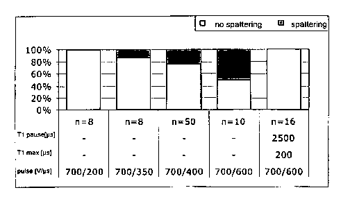
Figure 2 is a bar chart of the spattering frequency depending on the
pulse duration, high throughput Nucleofector (HT-beta, Amaxa
GmbH), volumes of the cell suspension: 20 pl, gap width of the
cuvette: 1.5 mm, ionic strength of the buffer solution: 129 mmo1/1
(electrical conductivity 7.2mS/cm), the black shaded area shows
the spattering frequency of the individual samples, n = number
of samples,
Figure 3 is a bar chart of the spattering frequency depending on the
interruption duration of the voltage pulse, high throughput
Nucleofector (HT-beta, Amaxa GmbH), volumes of the cell
suspension: 20 pl, gap width of the cuvette: 1.5 mm, ionic
strength of the buffer solution: 203 mmo1/1 (electrical
conductivity 11.3mS/cm), the black shaded area shows the
spattering frequency of the individual samples, n = number of
samples,
Figure 4 is a bar chart of the spattering frequency depending on the
maximum duration of an uninterrupted voltage interval, high
throughput Nucleofector (HT-beta, Amaxa GmbH), volumes of
the cell suspension: 20 pl, gap width of the cuvette: 1.5 mm,
ionic strength of the buffer solution: 203 mmo1/1 (electrical
conductivity 11.3mS/cm), the black shaded area shows the
spattering frequency of the individual samples, n = number of
samples,
Figure 5 is a bar chart of the spattering frequency depending on the
electrical conductivity and/or ionic strength of the buffer solution,
high throughput Nucleofector (HT-beta, Amaxa GmbH),
volumes of the cell suspension: 20 pl, gap width of the cuvette:
1.5 mm, ionic strength of the buffer solution:), the black shaded
area shows the spattering frequency of the individual samples,
n = number of samples, buffer 1: ionic strength 203 mmo1/1 and
CA 02613984 2008-01-02
WO 2007/006487
PCT/EP2006/006620
electrical conductivity 11.3mS/cm, buffer 2: ionic strength 129
mmo1/1 and electrical conductivity 7.2 mS/cm,
Figure 6 is a bar chart of the spattering frequency depending on the
volume of the cell suspension, high throughput Nucleofector
(HT-beta, Amaxa GmbH), gap width of the cuvette: 1.5mm,
ionic strength of the buffer solution: 129 mmo1/1 (electrical
conductivity 7.2mS/cm), the black shaded area shows the
spattering of the individual samples, n = number of samples,
Figure 7 is a bar chart of the spattering frequency depending on the
volume of the cell suspension, high throughput Nucleofector
(HT-beta, Amaxa GmbH), gap width of the cuvette: 1.5 mm,
ionic strength of the buffer solution: 203 mmo1/1 (electrical
conductivity 11.3mS/cm), the black shaded area shows the
spattering frequency of the individual samples, n = number of
samples,
Figure 8 is a bar chart of the transfection efficiency depending on the
interruption duration of the voltage pulse, high throughput
Nucleofector (HT beta, Amaxa GmbH), gap width of the
cuvette: 1.5 mm, ionic strength of the buffer solution: 203 mmo1/1
(electrical conductivity 11.3mS/cm), for detecting the
transfection efficiency respectively 2 x 10⁵ HEK293 cells are
received in 20 pl buffer solution, with 0.1 pg pEGFP-C1
(Invitrogen) added and exposed to a field of 4 kV/cm, then the
cells were received in Minimum Essential Medium Eagle
(ATCC) with 100 pg/ml streptomycin, 100 U/m1 penicillin and
10% horse serum (ATCC) and cultivated in a humidified
incubator for 24 hours at 37 C and 5% CO2, finally the samples
were tested for GFP expression, by means of flow cytometry
(FACSCalibur, Becton Dickinson), the respective double values
of the percentage of the GFP expressing cells are shown, the
bar chart text relates to the interruption of the field exposure; all
CA 02613984 2008-01-02
WO 2007/006487
PCT/EP2006/006620
11
data are in ps, the numbers at the start and the end represent
the duration of the uninterrupted voltage intervals, the numbers
between the horizontal lines representing the interruption
duration there between (P=pause) and
Figure 9 is a bar
chart of the transfection efficiency depending on the
interruption duration of the voltage pulse, high throughput
Nucleofector (HT-beta, Amaxa GmbH), gap width of the
cuvette: 1.5 mm, ionic strength of the buffer solution: 203 mmo1/1
(electrical conductivity 11.3mS/cm), for the detection of the
transfection efficiency respectively 2 x 10⁵ jurkat E6.1 cells are
received in 20 pl buffer solution with 1 pg pmaxGFP (Amaxa)
added and exposed to a field of 1.25 kV/cm, then the cells were
received in RPM1-1640 medium (ATCC) with 100 pg/ml
streptomycin, 100 Wm! penicillin and 10% FCS (ATCC) and
cultivated for 24 hours at 37 C at 5% CO2 in a humidified
incubator, finally the samples were examined for GFP
expression by means of flow cytometry (FACSCalibur, Becton
Dickinson), the respective double values of the percentage of
the GFP expressing cells are shown, the bar chart text relates
to the interruption to the field exposure: all data are in ps, the
numbers at the start and the end represent the duration of the
uninterrupted voltage intervals, the numbers between the
horizontal lines representing the interruption duration there
between (P=pause).
Detailed Description of Various and Preferred Embodiments
Figure 1 shows a bar chart of the spattering frequency depending on the
voltage in the form of a comparison of two different voltage pulses, which
were carried out respectively with and without interruption. The first voltage
pulse has a preset duration of 100 ps at an externally applied voltage of 800
V. This provides for a field strength of approximately 4 kV/cm which can be
CA 02613984 2008-01-02
WO 2007/006487
PCT/EP2006/006620
12
calculated from the voltage and the electrode resistance. The second voltage
pulse also has a preset duration of 100 ps but with an applied voltage of 1000
V, a field strength of approximately 5 kV/cm can be calculated from the
voltage. The two voltage pulses were respectively interrupted twice after 40
ps (Ti max), i.e. the pulse was interrupted after 40 ps, then continued, after
a
further 40 ps again interrupted and finally completed with a voltage interval
of
20 ps, so that a total preset duration of 100 ps was reached. The durations of
the interruptions were respectively 800 ps (T1 pause). As a whole, each
voltage pulse therefore is made up of 3 voltage intervals and 2 interruption
intervals, the entire duration of the pulses adding up to a total of 1700 ps.
It is
clear here that applying the voltage pulse with the lower voltage and/or field
strength under the preset conditions does not result in expulsion of the
samples, i.e. in this case it does not spatter. In contrast, the voltage pulse
at
the higher voltage and/or field strength leads to expulsion of the samples
(third bar). This undesirable spattering may be prevented by interrupting the
voltage pulse twice (last bar). It therefore shows, on the one hand, that the
spattering probability under otherwise constant conditions becomes higher
with increasing field strength, and on the other hand, that an expulsion of
the
sample from the reaction container, even at very high field strengths, may be
prevented by interrupting the voltage pulse. At least by interrupting the
pulse
the probability of spattering is significantly reduced.
Figure 2 shows a bar chart of the spattering frequency depending on the
pulse duration, whereby voltage pulses were used with a strength of
respectively 700 V (3.5 kV/cm field strength), with increasing preset duration
of 200, 350, 400 and 600 ps. It was shown that the percentage frequency of
spattering increases with increasing pulse duration. Interrupting the voltage
pulse according to the invention with the longest preset duration of 600 ps
the
spattering of the samples could however be effectively prevented. The
voltage pulses were, to this end, respectively interrupted twice after 200 ps
(T1 max), i.e. the pulse was interrupted after 200 ps then continued, after a
further 200 ps again interrupted and finally completed with a voltage interval
of 200 ps again, so that a total preset duration of 600 ps was achieved. The
interruption durations were respectively 2.5 ms (Ti pause). In total, each
CA 02613984 2008-01-02
WO 2007/006487
PCT/EP2006/006620
13
voltage pulse is made up of 3 voltage intervals and 2 interruption intervals,
the total duration of the pulse adding up to a total of 5.6 ms. This makes
clear
that with a relatively long preset duration of the voltage pulse there is a
high
probability that it leads to expulsion of the samples (fourth bar). This
undesired spattering may be prevented by interrupting the voltage pulse twice
(last bar). Thus, on the one hand, it is shown that the probability of
spattering
under otherwise constant conditions becomes higher with increasing pulse
duration and, on the other hand, that an expulsion of the sample from the
reaction vessel may be prevented even with a relatively long preset duration
by interrupting the voltage pulse.
Figure 3 shows a bar chart of the spattering frequency depending on the
durations of the interruption of the voltage pulse. It is clear that in this
example that at least for specific applications and/or conditions by extending
the durations of the interruption(s) the probability of the expulsion of the
sample may be further reduced. A voltage pulse with a voltage of 700 V
(3.5kV/cm) field strength) and a preset duration of 600 ps was used
uninterrupted (first bar), interrupted 11 x for every 400 ps (second bar) or
interrupted 11 x for every 800 ps (third bar). The interrupted pulses
therefore
are made up of 12 voltage intervals of respectively 50 ps in length (Ti max)
and 11 interruption intervals of respectively 400 ps or 800 ps (Ti pause). If
the voltage pulse is not interrupted according to the invention under these
conditions, spattering occurs at each test and/or each sample. Whilst
spattering occurs at an interruption duration of 400 ps, for approximately 70%
of the samples, the spattering however may be completely prevented under
these conditions by doubling the interruption durations. Naturally, the
relationship between the substances in the buffer solution 'calms down' with
the increasing length of interruption(s) so that, during the voltage interval
following the interruption, gas is no longer formed in the sample.
Figure 4 shows a bar chart of the spattering frequency depending on the
maximum duration of an uninterrupted voltage interval. This test was carried
out practically under the same conditions as the test according to Figure 3,
with the difference that the interruption durations (Ti pause) were maintained
CA 02613984 2008-01-02
WO 2007/006487
PCT/EP2006/006620
14
constant at 400 ps, whilst the maximum length of the voltage intervals (Ti
max) i.e. the durations in which the electrical field is generated was varied.
When comparing the tests with Ti max = 100 ps and Ti max = 40 ps, it is
clear that a shortening of the voltage interval i.e. the time until the
voltage
pulse is interrupted, leads to a reduction of the probability of spattering.
Moreover, in the present embodiment several factors indicate here that a
threshold value between 40 and 50 ps exists, i.e. in this case there is no
proportional dependency of the spattering frequency on T1 max.
Figure 5 shows a bar chart of the spattering frequency depending on the
electrical conductivity and/or ionic strength of the buffer solution. When
using
a buffer with higher ionic strength (buffer 1: ionic strength 203 mmo1/1 and
electrical conductivity 11.3 mS/cm) the risk of spattering is substantially
greater than when using a buffer with lower ionic strength (buffer 2: ionic
strength 129 mmo1/1 and electrical conductivity 7.2 mS/cm). In both examples
shown, the spattering may, however, be prevented by the interruption of the
voltage pulse according to the invention.
Figures 6 and 7 show respectively a bar chart of the spattering frequency
depending on the volume of the cell suspension. From both illustrations it is
clear that the probability of spattering is higher, the lower the volume of
the
cell suspension and/or buffer solution. In this connection, the example
according to Figure 6 shows that, even in applications where only very low
volumes may be used, the spattering probability may practically be reduced
to zero.
Figures 8 and 9 respectively show a bar chart of the transfection efficiency
depending on the interruption duration of the voltage pulse. The transfection
efficiency is surprisingly not negatively affected by the interruption of the
voltage pulse according to the invention. The efficiency of the method is
always approximately at the same high level, irrespective of whether the
voltage pulse is interrupted (double bars 2 to 5) or not (double bars 1 and
6).
CA 02613984 2008-01-02
WO 2007/006487
PCT/EP2006/006620
As a whole it is therefore shown that under otherwise prescribed conditions
(field strength and/or current density, preset duration of the voltage pulse,
volume of buffer solution) a voltage interval may not exceed a specific
uninterrupted length, in order to prevent sufficiently the occurrence of
spattering and/or the probability of expulsion of the sample from the reaction
vessel. Thus the spattering problem under otherwise preset conditions can be
solved by the pulse being interrupted and/or a voltage interval not exceeding
a critical uninterrupted length. Therefore, the interruption of the voltage
pulse
leads to a marked reduction of the spattering probability, without the quality
of
the method, in this case in particular the transfection efficiency, being
impaired.