Note : Les descriptions sont présentées dans la langue officielle dans laquelle elles ont été soumises.
CA 02614343 2008-01-04
WO 2007/016255 PCT/US2006/029214
LOCKING MECHANISM FOR MOVABLE SUBFRAME OF TRACTOR-TRAILERS
CROSS-REFERENCE TO RELATED APPLICATION
This application claims the benefit of U.S. Provisional Patent Application
Serial No.
60/703,910, filed on July 29, 2005.
BACKGROUND OF THE INVENTION
TECHNICAL FIELD
The invention relates to tractor-trailer subframes and, in particular, to
movable subframes for
tractor-trailers. More particularly, the invention is directed to a movable
subframe for tractor-
trailers which includes a clamping arm mechanism for loclcing the movable
subfraine into a selected
position relative to the tractor-trailer body, wherein the movable subframe is
effectively clamped to
the trailer body rails so that gyrations of the subframe are reduced or
minimized after the subframe
is locked into position and during operation of the vehicle, tliereby enabling
the use of weight-
saving aluminum trailer body rails and cross sills and enhancing the
advantages of an aluininum
slider box.
BACKGROUND ART
Specifically, movable subframes, typically referred to as slider boxes, slider
subframes,
slider undercarriages, or slider secondary fraines, have been utilized on
tractor-trailers or semi-
trailers for many years. One or more axle/suspension systems usually are
suspended from a single
slider box. For purposes of clarity, hereinafter the movable subframe
incorporating the improved
loclcing mechanism of the present invention will be referred to as a slider
box. It is understood that
a slider box outfitted with usually two axle/suspension systems typically is
refei7ed to as a slider or
slider tandem, and again, for purposes of clarity will hereinafter be referred
to as a slider tandem.
The slider tandem in turn is mounted on the underside of the trailer primary
frame or floor structtire,
and is movable longitudinally therealong to provide a means for variable load
distribution and
1
CA 02614343 2008-01-04
WO 2007/016255 PCT/US2006/029214
vehicular maneuverability. Specifically, the slider tandem can be used on
flatbeds having a primary
frame, van trailers having a floor structure, and the like.
More specifically, the amount of cargo that a trailer may carry is governed by
local, state
and/or national road and bridge laws, and is dependent on proper load
distribtition. The basic
principle behind most road and bridge laws is to limit the maximum load that a
vehicle may carry,
as well as limit the maximum load that can be supported by individual axles. A
trailer having a
slider tandem gains an advantage with respect to laws governing maximum axle
loads. More
particularly, proper placement of the slider tandem varies individual axle
loads or redistributes the
trailer load so that it is within legal limits.
Conventional or prior art slider box designs were developed before the advent
of air
suspension systems for trailers. At that time, leaf spring suspension systems
were the suspension of
choice for van trailers with slider boxes. However, the leaf spring suspension
system was unable to
provide adequate load equalization between the axles of the slider tandem and
therefore was stibject
to possible overload situations.
Moreover, the subsequent development of air suspension systems provided load
equalization
among multiple axles for tractor-trailers, with or without the utilization of
slider boxes, as well as
improved ride quality for individual axles. Of course, the combination of a
movable slider box and
an air suspension system provided maximum versatility with respect to variable
load distribution
and load equalization in a trailer and increased maneuverability.
Unfortunately, prior art slider
boxes equipped with air suspensions add unwanted weight to the trailer,
primarily because those
slider boxes were originally built to support leaf spring suspensions and
adapting them to
incorporate air suspensions required additional bracing and support.
Additionally, vehicles containing more than one non-steerable axle, including
tractor-
trailers, are subject to lateral or side loads. Lateral loads can act through
the slider box in opposite
directions, and the effect of such lateral or bending loads on the slider box
can be significant.
Moreover, a slider box is subjected to strong vertical and longitudinal or
fore-aft loads. Thus, the
loads to which the slider box is subjected must be controlled by the slider
box design. Prior art
slider box designs control vertical loads by utilizing rigid, and therefore
heavy, main members and
cross meinbers typically made of steel. This increases the weight of the
fiame, thereby reducing the
2
CA 02614343 2008-01-04
WO 2007/016255 PCT/US2006/029214
amount of payload that can be carried by the tractor-trailer as governmental
weight limitations
remain constant irrespective of the weight of the vehicle.
Thus, within the trucking industry, reducing the weight of carrier equipment
without
sacrificing durability directly improves productivity by increasing the
available payload that can be
transported by the vehicle. Slider boxes made of steel have contributed to the
excessive weight
problems that have plagued slider tandems in the past. Although certain prior
art slider boxes
formed of steel have exhibited weight and durability improvement over other
prior art steel slider
boxes, as well as improvements to the structure and operation of prior art
retractable pin
mechanisms, the truclcing industry is continually striving for improvement in
slider box design.
However, attempts to utilize materials that are lighter than steel to
construct slider boxes, such as
aluminum, have been largely unsuccessful and inefficient.
Turning now to the manner in which a slider tandem operates, once properly
positioned, the
slider tandem heretofore typically has been locked into place on the underside
of the trailer by a
retractable pin mechanism. The retractable pin mechanism of the prior art
generally includes two or
more, and typically four, retractable pins which may be interconnected by a
usually manually
operated crank mechanism. When the pins are in their extended or outboardmost
position, they
each pass through a respective opening formed in the slider box and a selected
aligned one of a
plurality of openings formed in rails of the trailer body. The pins thereby
lock the slider tandem in
the selected position relative to the trailer body. However, these pins can
become jammed. The
meclianical advantage enjoyed by the manual operator of the pin mechanism ,
which is used for
retracting the pins when it becomes necessary to reposition the slider tandem,
is designed to
overcome spring forces which bias the pins to the locked position. The
mechanical advantage is not
designed to free or retract jammed pins from their locked position. Since the
mechanical advantage
is soinetimes inadequate, prior art slider tandem pin mechanisms rely on
either the brute force of the
tractor-trailer operator or add-on devices designed to release jammed pins.
In assessing the causes for jammed pins, it has been discovered that shear
forces are imposed
on the individual pins. The shear forces operate on the pin peipendicular to
the longitudinal axis of
each cylindrical pin. More specifically, slight movement of the slider tandein
relative to the trailer
body during operation of the tractor-trailer can cause slight misalignment
between the respective
3
CA 02614343 2008-01-04
WO 2007/016255 PCT/US2006/029214
slider box and trailer body openings through which each pin extends or passes
when in the locked
position. This misalignment can in turn cause contact pressure points between
each pin and its
respective trailer body rail opening, aligned slider box opening, and the
mounting bracket opening
located adjacent to the inboard end of the pin. The contact pressure points in
turn cause the above-
mentioned shear forces on the pins. Such whipsaw-like or jamming forces can
become greater than
the force that a tractor-trailer operator is, able to manually apply through
the crank mechanism to
free the pins.
Thus, when prior art pins become jammed, the operator of the tractor-trailer
risks personal
injury due to overexertion in attempting to manually free jammed pins, and
fiirther risks damaging
the retractable pin mechanism. Specifically, a typical method of attempting to
release prior art
jammed pins is for the tractor-trailer operator to rock the trailer fore and
aft, while an assistant
operates the retractable pin mechanism. The rocking motion momentarily
realigns the misaligned
openings, so that the assistant can retract the pins during the brief period
of realignment. The
proc,ess has been simplified by a prior art quiclc-release device which allows
the vehicle operator to
maneuver the trailer while the quick release device automatically frees the
jammed pins, thus
effectively obviating the need for another person to operate the crank
mechanism. However, such
quick release devices add expense to the slider box, and such an exercise can
be time-consuming
and also can create wear on the retractable pin mechanism.
Yet another problem associated with prior art locking pins, which is related
to the pin
jamming problem, is that the holes formed in the trailer body rails and
through which the slider box
pins protnide when in the locked position, are approximately 0.25" oversized
to allow the pins to
pass through the respective holes after tolerances and deflections are
accounted for. This relatively
sloppy fit allows the slider box pins to gyrate back and forth and up and down
witliin the holes
during trailer operation. Such movements, in turn, can cause each pin to
forcibly contact, or bang,
the trailer body rail opening at the interface of the slider pin and the
trailer body rail. Such
movement and pin banging, in turn, causes lateral movement and misalignment of
the slider tandem,
which can adversely affect tracking, cause excessive tire wear, and exacerbate
the jamming of pins.
This movement also places additional and undesirable stresses on the slider
box and the trailer body
rails, and dictates that those components be made of steel, as opposed to a
lighter material such as
4
CA 02614343 2008-01-04
WO 2007/016255 PCT/US2006/029214
aluminum, to provide acceptable component life. The steel body rails alone add
approximately 100
lbs. apiece to the weight of the trailer and furtlier dictate the use of steel
cross sills in trailers having
a floor structure frame, which enables easy welding of the steel rails to the
steel floor structure but
also adds additional undesirable weight. As there are approximately 17 cross
sills on a typical
5- trailer floor structure in the slider area, substantial weight savings
could be achieved through the use
of sills made of aluminum, as opposed to steel.
Thus a need exists in the art for an improved locking mechanism for a slider
box that
overcomes the problems and deficiencies of the prior art, mainly unwanted
movement, gyrations
and pin jamming, aVd yet still allows the slider box to be constructed of
lightweight materials in
order to provide vehicle operators an improved slider box that can carry
larger payloads.
BRIEF SUMMARY OF THE INVENTION
An objective of the present invention is to provide a slider box incorporating
an improved
locking mechanism that securely fastens a slider tandem to the trailer body
rails of a tractor-trailer.
Another objective of the present invention is to provide a slider box
incorporating an
improved loclcing mechanism that allows the operator to easily lock and unlock
the slider tandem
for easy repositioning of the slider tandem with respect to the trailer body
rails, while effectively
substantially minimizing the stresses associated with the relatively loose fit
of prior art locking pin
mechanisms.
Yet another objective of the present invention is to provide a slider box
incorporating an
improved loclcing mechanism that allows for the use of lighter materials, such
as aluminum, in
constiLicting the trailer body rails, cross sills, and other components of the
slider box, and which in
turn significantly reduces the overall weight of the trailer, thereby
improving cargo-carrying
efficiency.
A fiirther objective of the present invention is to provide a slider box
incorporating an
improved loclcing mechanism that reduces the amount of effort expended by
the.operator when
repositioning the slider tandem, and further permits the operator to easily
determine whether the
slider box is properly engaged, thereby improving safety for the operator and
the traveling public.
5
CA 02614343 2008-01-04
WO 2007/016255 PCT/US2006/029214
These objectives and advantages are obtained by the movable subframe for a
tractor-trailer
which includes a pair of transversely spaced-apart main members extending
longittidinally relative
to a longitudinally-extending trailer body of the tractor-trailer, at least
one cross member extending
between and being attached to the main members, at least one axle/suspension
system mounted on
and depending from the subframe, and at least one clamping mechanism mounted
on the subframe
for clampingly engaging the trailer body for selectively positioning the
subfiame relative to the
trailer body.
BRIEF DESCRIPTION OF THE SEVERAL VIEWS OF THE DRAWINGS
The preferred embodiment of the invention, illustrative of the best mode in
which applicant
has conte:mplated applying the principles of the invention, is set forth in
the following description
and is shown in the drawings, and is particularly and distinctly pointed out
and set forth in the
appended claims.
FIG. 1 is a driver's-side top-front fragmentary perspective view of a prior
art slider box for a
tractor-trailer, showing the retractable pin mechanism used to selectively
position the slider box
along the underside of a trailer body, and further showing depending hangers
for suspending
axle/suspension systems fiom the slider box;
FIG. 2 is an enlarged fiagmentary driver's-side elevational view of a prior
art slider tandem,
including the prior art slider box shown in FIG. 1, and showing two
axle/suspension systems, with
portions broken away and hidden portions represented by broken lines;
FIG. 3 is a reduced-size rear fragmentary elevational view of the prior art
slider tandem
shown in FIG. 2 movably mounted on the underside of a trailer body, with
portions thereof
represented by broken lines;
FIG. 4 is a greatly-enlarged fragmentary view taken from the circled area in
FIG. 3, showing
one of the pins of the retractable pin mechanism in the locked position;
FIG. 5 is a greatly-enlarged fragmentary top view of the retractable pin
mechanism of the
prior art slider box shown in FIG. 1, with portions thereof in section and
hidden portions
represented by broken lines, and showing one of the pins of the retractable
pin mechanism in an
6
CA 02614343 2008-01-04
WO 2007/016255 PCT/US2006/029214
unlocked position and showing the pin opening of the slider box slightly mis-
aligned with the pin
opening of the trailer body;
FIG. 6 is a view similar to FIG. 5, showing one of the pins of the retractable
pin mechanism
of the prior art slider box in a locked position and showing contact pressure
points imparted on the
pin as a result of the ordinary movement of the slider box relative to the
trailer body during
operation of the vehicle;
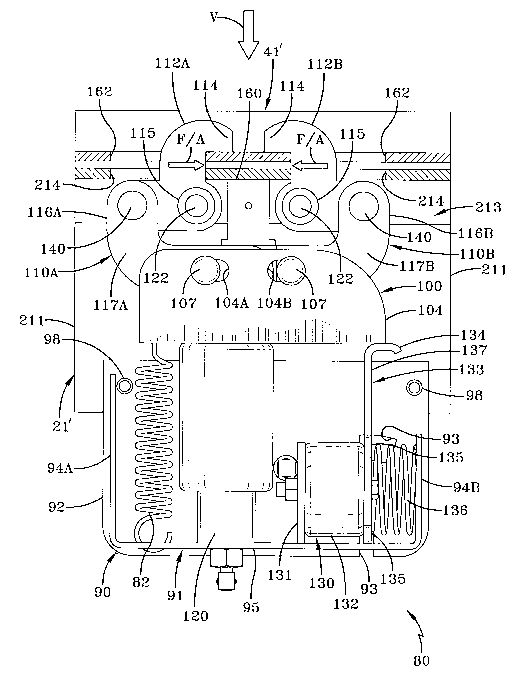
FIG. 7A is an enlarged outboard perspective view of the driver's side improved
loclcing
mechanism for a slider box of the present invention, showing the clamping arm
mechanism
including the housing, the aim base, and the clamping arms;
FIG. 7B is a condensed view similar to FIG.7A with a portion of the arm base
and one of the
front L-shaped plates removed, showing the front opening in the spacer, and
with the outboard
housing plate removed and showing the location of the air spring, the coil
springs, and the loclcing
mechanism within the housing;
FIG. 8A is a top driver's side perspective view of the improved loclcing
mechanism of the
present invention incorporated into a slider tandem, and showing the clamping
arm mechanism
locking the tandem into a selected position on the rails of a trailer body;
FIG. 8B is an enlarged fragmentary top-front outboard perspective view of the
improved
locking mechanism for a slider box of the present invention with portions of
the trailer body rail
removed, showing the manner in which the upper arms of one of the clamping arm
mechanisms
engages its respective trailer body rail for locking a slider tandem in a
selected position beneath the
trailer;
FIG. 9 is an outboard elevational view of the improved locking mechanism for a
slider box
of the present invention, with the outboard housing plate removed and showing
the slider box main
member and trailer body rail in section, and further showing the clamping arm
mechanism in an
unlocked position; ,
FIG. 10 is a view similar to FIG. 9, but showing the clamping arm mechanism in
a partially
locked position; and
FIG. 11 is a view similar to FIGS. 9 and 10, but showing the clamping arm
mechanism in a
loclced position.
7
CA 02614343 2008-01-04
WO 2007/016255 PCT/US2006/029214
Similar numerals refer to similar parts throughout the drawings.
DETAILED DESCRIPTION OF THE INVENTION
So that the structure, operation and advantages of the improved loclcing
mechanism for a
slider box of the present invention can be best understood, a slider box for a
tractor-trailer having a
prior art retractable locking pin mechanism is indicated generally at 20 and
is shown in FIG. 1.
Slider box 20 includes a pair of longitudinally extending main members 21, a
plurality of cross
members 22A through F, and a retractable pin mechanism 24. Front and rear
pairs of hangers 23A
and 23B, respectively, are attached to and depend from slider box main members
21 for suspending
axle/suspension systems.
Specifically, and as further shown in FIG. 2, each main meniber 21 is an
elongated,
generally C-shaped beam made of a metal such as steel or other suitable
material. The open portion
of each main member 21 is opposed to the open portion of the other main member
and faces inboard
relative to slider box 20. Main members 21 are connected to each other in
spaced-apart parallel
relationship by cross members 22A-F, which extend between in fore-aft spaced-
apart parallel
relationship and are perpendicular to main members 21. Each end of each cross
member 22 nests in
the open portion of a respective one of main members 21, and is secured
therein by any suitable
means such as welding or mechanical fastening. Each cross member 22 is a
generally C-shaped
beam also made of a metal such as steel or other suitably robust material, and
has a plurality of
openings 29 formed in its vertically extending surface. Openings 29 are
aligned with corresponding
openings formed in the other cross members 22 to provide for passage of air
and/or fluid conduits,
electrical lines, and the like, used in the operation of the tractor-trailer
(not shown). Each front
hanger 23A is attached by welding or other suitable means, to the lowermost
surface of a respective
one of main members 21 at a location directly beneath cross members 22A, B.
Each rear hanger
23B similarly is attached to main members 21 at a location directly beneath
cross members 22D, E.
Each main member 21 has a pair of rail guides 25 mounted on its outboard
surface by bolts
26, or other suitable means of attachment, such as welding. Each rail guide 25
is mounted adjacent
to a respective one of the ends of main member 21. A low friction strip 27 is
attached to the
uppermost surface of each main member 21 by recessed fasteners 28, and extends
generally the
8
CA 02614343 2008-01-04
WO 2007/016255 PCT/US2006/029214
entire length of main member 21. Low friction strip 27 is formed of any
suitable low-friction
material, such as ultra-high molecular weight polyethylene.
As mentioned hereinabove, and as best shown in FIG. 2, slider box 20 supports
front and
rear axle/suspension systems 30A and 30B, respectively, wherein the slider box
and axle/suspension
systems combine to form a slider tandem, which is indicated generally at 70 in
FIG. 2. Inasmuch as
each axle/suspension system 30A,B is suspended from slider box 20, but does
not form an integral
part thereof, only the major components of system 30 will be cited for aiding
in the description of
the environment in which the slider box and prior art retractable pin
mechanism 24 operates. Each
axle/suspension system 30A,B includes generally identical suspension
assemblies 31 suspended
from respective pairs of hangers 23A,B. Each suspension assembly 31 includes a
suspension beam
32 which is pivotally mounted on hanger 23 in a usual manner. An air spring 33
is suitably mounted
on and extends between the upper surface of the rearwardmost end of suspension
beam 32 and main
member 21 at a location directly beneath a certain one of the cross members
22C,F. A shock
absorber 34 extendsAbetween and is mounted on suspension beam 32 and the
certain cross member
22C,F. One or more reinforcement struts 60 are strategically attached within
each cross member
22C,F to strengthen the cross member for supporting suspension assemblies 31.
Other components
of suspension assembly 31, mentioned herein only for the sake of relative
completeness, include an
air bralce 35 and a height control valve 36. An axle 37 extends between and is
captured in the pair of
suspension beams 32 of each axle/suspension system 30A,B. Wheels 38 are
mounted on each end of
axle 37.
Slider tandem 70 is movably mounted on trailer body 40 (FIGS. 3 and 4) by
slidable
engagement of rail guides 25 with spaced apart, parallel, and generally Z-
shaped rails 41, which are
mounted on and depend from the underside of a floor stiucture 61 of the
trailer body. More
specifically, each Z-shaped rail 41 preferably is typically foimed of a metal
such as steel and weighs
about 100 pounds. Since steel Z-shaped rails 41 conventionally are welded to
floor structure 61 of a
trailer body 40, cross sills 55 of the floor structure also conventionally are
formed of steel to
facilitate welding. Cross sills 55, which support floor structure 61 of the
trailer, typically number
about 17 within the area directly above Z-shaped rails 41. Each low friction
strip 27 abuts the
bottom surface of the uppermost portion of a respective one of Z-shaped rails
41 to provide a
9
CA 02614343 2008-01-04
WO 2007/016255 PCT/US2006/029214
smooth, generally friction-free contact surface for slidable movement of
slider tandem 70 beneath
trailer body 40. =
As is well-lrnown in the art, slider tandem 70 can be selectively positioned
relative to trailer
body 40 for optimum load distribution by retractable pin mechanism 24. As best
shown in FIGS. 1,
3 and 4, pin mechanism 24 includes a generally L-shaped handle 42, which
passes through an
opening 39 formed in a selected one of main members 21, but usually on the
driver's side of the
tractor-trailer. It can be seen that the bent end portion of handle 42, which
extends outwardly from
the outboard side of main member 21, is accessible for easy grasping by an
operator of the tractor-
trailer. The inboard end of handle 42 is pivotally attached to an arm or a
lever 43, which in ttirn is
pivotally attached to a pair of arms 44 which extend in opposite outboard
directions from lever 43.
Lever 43 further is attached to an elongated, longitudinally extending pivot
rod 45 which passes
rearwardly through a plurality of aligned openings 46 formed in cross members
22. The rear end of
pivot rod 45 remote from lever 43 similarly is attached to a remote lever 47,
which in ttirn is
pivotally attached to a pair of arms 48 which extend in opposite outboard
directions from the remote
lever. The outboard end of each one of arms 44, 48 is bent (FIG. 5) and is
pivotally attached to the
inboard end of a prior art locking pin 49.
The inboard end of each prior art loclcing pin 49 is slidably mounted (FIG. 5)
in an opening
50 fonned in a bracket 51 which is attached by suitable means such as welding
to a respective one
of cross menibers 22A and 22F. The enlarged cylindrical outboard end of each
locking pin 49
passes through a generally round or circular-shaped opening 52 formed in a
respective one of main
members 21. When it is desired to lock slider tandem 70 in a selected position
relative to trailer
body 40, the slider box main member openings 52 are aligned with selected ones
of a plurality of
correspondingly sized openings 53 formed in Z-shaped rails 41 of the trailer
body. Each loclcing pin
49 automatically passes through the selected aligned openings 52,53 since the
locking pin is biased
in an otitboard direction by a coil spring 54 captured between bracket 51 and
the enlarged otitboard
end of locking pin 49. When it is again desired by the operator of the tractor-
trailer to move slider
tandem 70 beneath trailer body 40, the parking bralce of the trailer is
engaged, handle 42 is pulled in
an outboard direction to retract pins 49 out of trailer rail openings 53 and
against the bias of springs
54, and slider 20 ismoved longitudinally along Z-shaped rails 41 until slider
box main member
CA 02614343 2008-01-04
WO 2007/016255 PCT/US2006/029214
openings 52 align with selected trailer rail openings 53 and prior art
loclcing pins 49 engage
tllerewith as described hereinabove for maximizing load distribution.
Due in part tdthe aforementioned problems associated with the use of prior art
locking pins,
including gyrations of slider tandem 70 due to the relatively sloppy fit of
loclcing pins 49 in aligned
openings 52,53 as the vehicle travels over-the-road, the above-described prior
art Z-shaped rails 41
and cross sills 55 of floor structure 61 are formed of steel. Forming such
components from steel
enables trailer body 40 and Z-shaped rails 41 to withstand such gyrations, but
using the steel
material increases the overall weight of the trailer which is undesirable and
inefficient.
Moreover, as is best shown in FIGS. 4 and 5 and especially FIG. 6, it can be
appreciated that
prior art loclcing pins 49 can become jammed during routine operation of
retractable pin mechanism
24. More particularly, shear forces are caused to operate on pins 49 when they
are in the extended
or locked position, because of slight movement of prior art slider box 20 and
its main members 21
relative to trailer body 40 and its Z-shaped rails 41, causing misalignment as
indicated by arrows M
in FIG. 6. Specifically, this movement results in slight misalignment between
slider box openings
52 and trailer body rail openings 53. The misalignment in turn causes contact
pressure points
between each pin 49 and its respective trailer body rail opening 53, slider
box main member
opening 52, and braclcet opening 50, as represented by arrows PP. The contact
point pressure in
turn causes the shear forces which operate on the pin perpendicular to the
longitudinal axis of each
pin to resist retraction of the pins to the unloclced position.
The mechanical advantage enjoyed by the manual operator of retractable pin
mechanism 24
must be greater than the combined shear forces acting on jammed pins 49 in
order to retract or free
the pins to the unloclced position shown in FIG. 5. However, the mechanical
advantage often is
inadequate, and so the operator must personally exert additional physical
force to free the jammed
pins. This type of overexertion by the operator can cause personal injury
and/or damage to
retractable pin mechanism 24. Specifically, a typical method of attempting to
release prior art
jammed pins is for the operator to roclc'trailer body 40 fore and aft, while
an assistant operates the
retractable pin mechanism. The roclcing motion briefly realigns misaligned
openings 52,53 so that
the assistant can retract the pins during the period of realignment. Also, add-
on devices designed to
release jammed pins, such as a prior art quick-release device which allows the
operator to maneuver
11
CA 02614343 2008-01-04
WO 2007/016255 PCT/US2006/029214
the trailer while the quiclc-release device automatically frees the jammed
pins, eliminates the need
for another person to operate the retractable pin mechanism. While the quick-
release device does
make fieeing jammed pins a one-person job, it still requires the operator to
rock the trailer which is
time consuming, can cause damage to the retractable pin mechanism, and adds
weight and
additional installation and maintenance expense.
The improved locking mechanism for a slider box of the present invention
eliminates the
tindesirable stresses and jamming associated with prior art retractable pin
mechanism 24 by
replacing the mechanism with the clamping arm locking mechanism of the present
invention,
thereby permitting the use of lighter materials, such as aluminum, to
construct the trailer body rails
and cross sills and enhancing the advantages of an aluniinum slider box.
The improved locking mechanism for a slider box of a tractor-trailer of the
present invention
is indicated generally at 80 and is shown in FIGS. 7 through 11. The
environment in which loclcing
mechanism 80 of the present invention operates is generally identical to that
described above for
prior art retractable pin mechanism 24, with any differences in structure and
operation between the
environment adapted for use with the present invention and that of the prior
art being particularly
described below. Inasmuch as a pair of clamping arm mechanisms 80 are utilized
on a slider box,
but are generally identical in structure and operation, only one will be
described herein.
Specifically, clamping arm mechanism 80 (FIGS. 7A and 7B) includes a housing
90, a coil
spring 82, an arm base 100, a pair of front and rear clamping arms 110A,B,
respectively, an air
spring 120, a loclcing mechanism 130, and an up-stop 160 (FIG. 9). Unless
otherwise indicated, all
components of clamping arm mechanism 80 are made of a metal such as steel,
aluminum, or other
suitable material. _
Housing 90 further includes a generally longitudinally extending elongated U-
shaped base
91, an inboard plate 92 and an outboard plate 96, which combine to form a
generally rectangular-
shaped box-like structure having a top opening 99. Inboard plate 92 and
otitboard plate 96 are
vertically disposed in spaced-apart parallel relationship, abut the inboard
and outboard edges,
respectively, of U-shaped base 91, and are removably connected to each other
and to slider box
main meinber 21 by pins or bolts 105 (FIG. 8B) that pass through outer metal
sleeves 98, as
described more fully below. U-shaped base 91 includes a first vertically-
disposed wall 94A, a
12
CA 02614343 2008-01-04
WO 2007/016255 PCT/US2006/029214
second veitical wa1L 94B and a horizontal bottom wall 95, and is positioned
between abutting
inboard and outboard plates 92,96, respectively, as illustrated in FIG. 7A, to
complete the structure
of housing 90. U-shaped base 91 further includes an opening 91A for the
receipt of a lower end of
air spring 120 and an aperture 91B for receipt of a lower end of coil spring
82 (FIG. 7B). More
specifically, coil spring 82 is vertically disposed and is captured between
the bottom wall 95 of U-
shaped base 91 and the lowermost portion of arm base 100, and is in biased
tension in a generally
vertical direction so as to assist in the lowering of arm base 100 relative to
bottom wall 95, as will
be described in greater detail hereinbelow. Inboard plate 92 is formed with a
plurality of openings
93 for receipt of tabs 135, as described more fully below and illustrated in
FIG. 9. Similarly,
outboard plate 96 is formed with a plurality of openings 97 for receipt of
tabs 135 (FIG. 7A), also as
described more fully below. Housing 90 serves to shield coil spring 82, air
spring 120, locking
mechanism 130 and, when clamping arm mechanism 80 is in the unlocked position,
ann base 100,
from debris and the elements, such as rain and snow, and also serves as a
mounting structure for the
coil spring, air spring, loclcing mechanism and clamping arm mechanism.
As best shown in FIG. 7B, locking mechanism 130 includes a dividing plate 131,
an actuator
132, a loclcing plate 133 and a coil spring 136. More particularly, dividing
plate 131 is a flat plate
and is generally perpendicular to, abuts and extends vertically upwardly from
bottom wall 95 of U-
shaped base 91, to which it is fixedly attached by any suitable means such as
welds, between air
spring 120 and actuator 132. Actuator 132 is positioned horizontally between
and is fixedly
attached at its respective ends to dividing plate 131 and locking plate 133 by
any suitable means.
Actuator 132 preferably is an air spring, but could be any device or mechanism
capable of moving
loclcing plate 133 in the direction of and against the bias of coil spring 136
until the coil spring is
compressed and the locking plate is disengaged from the lowermost portion of
arm base 100 (see
FIG. 10). Locking plate 133 is an inverted generally L-shaped plate having a
top horizontal flange
134 and a lower vertical portion 137. The plurality of tabs 135 protrude
outwardly from loclcing
plate lower portion 137 in both the inboard and outboard directions and
perpendicular to inboard
and outboard housing plates 92,96, respectively. When housing 90 is fully
assembled, tabs 135
extend through inboa.rd housing plate openings 93 and outboard housing plate
openings 97. When
in the locked position, as shown in FIG. 11, loclcing plate 133 is generally
perpendicular to, and
13
CA 02614343 2008-01-04
WO 2007/016255 PCT/US2006/029214
extends vertically upwardly from, bottom wa1195 of U-shaped base 91. Coil
spring 136 is captured
between and fixedly attached to locking plate lower portion 137 and second
wall 94B of U-shaped
base 91, aiid is in biased compression against the loclcing plate lower
portion. The operation of
locking mechanism 130 also will be described in greater detail hereinbelow.
Arm base 100 (FIGS. 7A and 7B) is also a generally U-shaped structure having a
generally
horizontal bottom wall 101, an inboard generally vertical side wall 102 and an
outboard generally
vertical side wall 104, and can be formed, extruded, or fabricated without
affecting the overall
concept of the invention. Arm base bottom wall 101 is fixedly attached to the
upper portion of air
spring 120 by any suitable means, and further includes a spring aperture 106
for receipt of the upper
portion of coil spring 82. As more fully described below, as airspring 120 is
inflated it overcomes
the tension in coil spring 82 and elevates arm base 100 in the direction of
trailer body rails 41'.
Inboard side wall 102 and outboard side wall 104 each is formed with a pair of
longittidinally spaced-apart openings, with the inboard openings not shown and
the outboard
openings indicated at 104A,B, for receipt of a base pin 107 therein. The
inboard openings and
outboard openings 104A,B each generally is a longitudinally elongated opening
to perrnit its
respective base pin 107 to move longitudinally therein during the operation-of
clamping arm
mechanism 80, as described more fully below. Arm base 100 preferably is
extruded, but also can be
formed or fabricated without affecting the overall concept of the invention.
Each one of fiont and rear clamping arms 110A,B, respectively, further
includes an upper
arm 112A,B and a lower arm 116A,B as best shown in FIGS. 7A and 7B. More
particularly, fiont
lower anii 116A includes a pair of generally L-shaped front plates 117A which
are disposed in
transversely-spaced parallel relationship to one another and are pivotally
attached to arm base 100
by base pin 107. Similarly, rear lower arm 116B includes a pair of generally L-
shaped rear plates
117B which are also disposed in transversely-spaced parallel relationship to
one another and are
also pivotally attached to arm base 100 by base pin 107. Each of front L-
shaped plates 117A
include a generally rounded rearward extension 119. A spacer 118 formed with a
front opening 300
and a rear opening (not shown), is disposed between the front and rear pairs
of spaced-apart L-
shaped plates 117A,B, respectively, which in turn are disposed between the
inboard and outboard
side walls 102,104, respectively, of arm base 100. More specifically, the
rearward end of spacer
14
CA 02614343 2008-01-04
WO 2007/016255 PCT/US2006/029214
118 is disposed between and fixedly attached to rear L-shaped plates 117B. The
forward end of
spacer 118 is disposed between and pivotally attached to the rearward
extensions 119 of front L-
shaped plates 117A by a pin (not shown), or other suitable means of pivotal
attachment. The pivotal
connection of the forward end of spacer 118 to front L-shaped plates 1 17A in
conjunction with the
fixed coiuzection of the rearward end of the spacer to rear L-shaped plates
117B forces front and
rear clamping arms 110A,B, respectively, to clamp in unison with one another.
Front L-shaped
plates 117A each is formed with an opening (not shown) which is aligned with a
selected pair of the
aligned inboard openings (not shown) and outboard openings 104A formed in side
walls 102,104,
respectively, of arm base 100 for the receipt of base pin 107 in the aligned
openings. Rear L-shaped
plates 117B each is formed with an opening (not shown) which is aligned with a
selected pair of the
aligned inboard openings (not shown) and outboard openings 104B formed in side
walls 102,104,
respectively, of arm base 100, and the rear opening of spacer 118 (not shown)
for the receipt of base
pin 107 in the aligned openings. More particularly, each one of front and rear
lower arms 116A,B,
respectively, is pivotally mounted on arm base 100 by insertion of base pin
107 in the inboard
direction through outboard side wall opening 104A,B, and the aligned openings
formed in the
outboardinost L-shaped plate 1 17A,B, the inboardmost L-shaped plate 117A,B,
and the inboard side
wall opening (not shown). Alternatively, base pin 107 can be inserted through
the same
components in the outboard direction without affecting the overall concept of
the invention. Once
base pin 107 is in place it can be secured by any suitable means such as a nut
(not shown).
Each one of front and rear upper arms 112A,B in turn is pivotally connected to
a respective
one of lower arms 116A,B by arm pin 140, as best illustrated in FIGS. 7A and
B. Each one of upper
arms 112 is a generally S-shaped plate foimed with an opening (not shown) for
receipt of arm pin
140. Each one of upper arms 112 further includes a mounting tube 115 that is
peipendicular to, and
extends outwardly from, the upper arm in both the inboard and outboard
directions. Mounting tube
115 preferably is cylindrical in shape and is hollow for receipt of a fastener
122 for rotatably
mounting clamping arm mechanism 80 to slider box main members 21', as best
shown in FIGS. 8A
and 8B, and described more fully below.
IIaving described the structure of clamping arm mechanism 80, the preferred
location of
clamping arm mechanism 80 on slider box 20 will now be described. To
accoininodate and mount
CA 02614343 2008-01-04
WO 2007/016255 PCT/US2006/029214
clainping arm mechanism 80 of the present invention, main members 21 and Z-
shaped rails 41 of
prior art slider box 20 must also be modified as described below. Inasmuch as
each one of the pair
of clamping ann mechanisms 80 mounted on respective ones of slider box main
meinbers 21' of the
present invention is generally identical in structure and operation, only one
of the mechanisms and
its attachment to its respective main member now will be described. In the
preferred embodiment of
the present invention, main member 21' is an inverted generally Y-shaped
structure defining a
continuous channel 215 (FIG. 8B). More particularly, main member 21' includes
an inboard leg
211, an outboard leg 212 and a top mounting structure 213. Main member 21' can
be formed,
fabricated, or extruded without affecting the overall concept of the present
invention, and preferably
is extruded of a light material such as aluminum. Top mounting structure 213
has a generally U-
shaped profile with a flat, generally vertical upper portion 216 on the
inboard side and an inboardly
facing, groove-defining upper portion 217 on the outboard side for engaging
trailer body rail 41' of
the present invention, as best illustrated in FIG. 8B. More particularly, rail
41' of the present
invention is extruded and includes a pair of iransversely spaced-apart,
generally Z-shaped members
41 1A,B. Z-shaped member 41 lA is located on the inboard side of rail 41', and
Z-shaped member
411 B is located on the outboard side of rai141' and further includes an
outboardly-extending tongue
portion 413 for engaging groove-defining upper portion 217 of main member 21'
as illustrated in
FIG. 8B. The tongue and groove relationship of groove-defining upper portion
217 and tongue
portion 413 permits movement of main members 21' and slider tandem 70 in the
longitudinal
direction relative to trailer body rails 41', but prevents the slider box from
disengaging from the
rails, when clamping arm mechanism 80 is in the unlocked position. In the
preferred embodiment
of the present invention, a low friction strip 170 is attached to portions of
the uppermost surface of
top mounting structure 213 and the inboard side of upper portion 216 with
interloclcing dovetails,
and extends generally the entire length of the top mounting structure. Strip
170 is formed of any
suitable low friction material, such as ultra-high molecular weight
polyethylene, and assists in
enabling generally smooth movement of slider box 20 along trailer body rails
41' and, ttnlilce the
prior art, generally prevents sticking along the sides of the rails.
Clamping arm mechanism 80 preferably is mounted on main member 21' adjacent to
and
forwardly of rear hanger 23B and between inboard leg 211 and outboard leg 212,
as best illustrated
16
CA 02614343 2008-01-04
WO 2007/016255 PCT/US2006/029214
in FIGS. 8A and 8B, and described more fully below. An up-stop 160 (FIG. 9)
also is mounted
with a bolt 161 on main member 21' between upper arms 112 of mechanism 80 and
between inboard
leg 211 and outboard leg 212 of main member 21'. More particularly, up-stop
160 preferably is
formed of aluminum or steel and is mottnted on the lowermost surface of and
depends from top
mounting structure 213, by any suitable means such as welding or with
fasteners, and preferably
with a bolt 161. Upstop 160 prevents the further upward movement of arm base
100 when
clamping arm mechanism 80 is in the loclced position (FIG. 11).
As previously described, clamping arm mechanism 80 is mounted on main member
21',
between inboard leg 211 and outboard leg 212, by fasteners 122, each one of
which extends through
respective aligned openings (not shown) formed in the inboard leg, mounting
tube 115 of each one
of upper arms 112, and the outboard leg; and by pins 105 which extend through
outer metal sleeves
98 of housing 90, inboard leg 211, and outboard leg 212. Fastener 122
preferably is a threaded or
shoulder bolt, but could also be a rivet or a pin without affecting the
overall concept of the present
invention. A second clamping arm mechanism 80 and up-stop 160 are mounted on
the opposite
main inember 21' at the same location, and in the same manner, so that the two
clamping arm
mechanisms 80 are in spaced-apart parallel relationship to one another. It
also is contemplated that
clamping ann mechanisms 80 can be located at other locations along main
members 21' without
affecting the overall concept of the present invention.
Having described the structure and location of the present invention, the
operation of
clamping arm mechanism 80 in the preferred embodiment of the present invention
now will be
described. As slider box 20 is being selectively slidably positioned beneath
trailer body 40,
clamping arm mechanism 80 is in the unlocked position as best illustrated by
FIG. 9. When
clamping arm mechanism 80 is in the unloclced position, air spring 120 is
fully deflated and arm
base 100 is imits lowermost position due to the biased tension in coil spring
82 which pulls the arm
base down toward bottom wall 95 of U-shaped base 91. Additionally, when
clamping arm
mechanism 80 is in the unlocked position, actuator 132 is fully inflated,
which clears locking plate
133 fiom contact with bottom plate 101 of arm base 100 by overcoming the bias
in coil spring 136.
After slider box 20 is positioned in its desired location relative to trailer
body 40, the
operator will activate the clamping arm mechanism 80 of the present invention
by any suitable
17
CA 02614343 2008-01-04
WO 2007/016255 PCT/US2006/029214
means such as by flipping a switch (not shown) or turning a lcey (also not
shown). Once clamping
arm mechanism 80 is activated, air spring 120 begins to inflate and actuator
132 begins to deflate.
As air spring 120 inflates, it overcomes the biased tension in coil spring 82
and elevates ami base
100 in an upward direction toward'rail 41', as best shown in FIG. 10. For the
convenience of the
reader, and looking at clamping arm mechanism 80 shown in the foreground in
FIG. 8A, from the
outboard direction in FIGS. 9 through 11, only the movement of the front
clamping arm 110Awi11
be described, though it is understood that the rear clamping arm 110B moves in
the same manner,
only in an opposite pivotal direction. As arm base 100 and front lower arm
116A move upward in
the direction of rai141', the lower arm rotates in a countercloclcwise
direction which, by virtue of its
comiection to front upper arm 112A by ann pin 140, in turn causes front upper
ann 112A to pivot
about fastener 122 in a cloclcwise direction as it moves through a selected
one of a plurality of
openings 214 formed in main member top mounting structure 213, and further
through an opening
162 foi7ned in rail 41', as best illustrated in FIGS. 8B and 10. Of course, it
is understood that a
plurality of pairs of openings 162 are formed along rail 41' for receiving
upper arms 112, to allow
for a large number of possible positions for slider box 20 beneath trailer
body 40. Upon full
inflation of air spring 120, a hook portion 114 of front upper arm 1 12A is in
mating contact with a
top surface of rail 4V as best shown in FIG. 11. As an important feature of
the present invention,
clamping arm mechanism 80 is designed so that upper arms 112 come into contact
with the top
surface of rail 41' at approximately the same time as up stop 160 comes into
contact with lower
arms 11 6A,B as shown in FIG. 11, thereby securely attaching clamping arm
mechanism 80 and
slider box 20 to rail 41'.
As yet another important feature of the present invention, actuator 132 is
deflated
simultaneously with the inflation of air spring 120 and elevation of arm base
100. As actuator 132
is deflated, the biased tension of coil spring 136 causes loclcing plate 133
to move in the direction of
dividing plate 131 to the upright position, and the top portion 134 of locking
plate 133 mates with
the lowermost surface of bottom plate 101 of arm base 100, as shown in FIG.
11. When in the
locked position, locking plate 133 prevents the downward movement of arm base
100, thereby
further securing the attachment of slider box 20 to rails 41'.
18
CA 02614343 2008-01-04
WO 2007/016255 PCT/US2006/029214
Similarly, when the operator desires to reposition slider box 20, or otherwise
disengage
clamping arm mechanism 80, the operator disengages clamping arm mechanism 80
by any suitable
means such as flipping a switch (not shown) or turning a key (also not shown),
which in turn causes
actuator 132 to inflate and disengage locking plate 133 from its contact with
bottom plate 101 of
arm base 100 by pushing loclcing plate 133 in the direction of and against the
bias of coil spring
136. Once locking plate 133 is disengaged from arm base 100, air spring 120 is
deflated which in
turn permits the biased tension in coil spring 82 to pull arm base 100
downward in the direction of
bottom wall 95. As arm base 100 is being lowered, front lower arm 116A pivots
in a clockwise
direction which, by uirhie of its connection to front upper arm 112A by arm
pin 140, in turn causes
front upper arm 112A to pivot about fastener 122 in a countercloclcwise
direction as it moves
downward through opening 162 in rail 41' and corresponding aligned opening 214
in main member
21'. It is understood that the same movements are simultaneously occurring on
the other clamping
aims of inechanism 80 nearest rear hanger 23B, only in the opposite pivotal
direction. More
specifically, as arm base 100 is lowered, rear lower arm 116B nearest rear
hanger 23B pivots in a
countercloclcwise direction which, by virtue of its connection to rear upper
arm 112B by arm pin
140, in turn causes rear upper arm 112B to pivot about fastener 122 in a
clockwise direction as it
moves downward through rail opening 162 and main member opening 214. Moreover,
unlike prior
art pins which had to be closely aligned to be engaged, hooks 114 have ample
clearance within
openings 162 and 214 to allow for slight misalignment, and are much less
lilcely to become jammed.
In accordance with another important feature of the present invention, the
operator of the
vehicle can easily deterinine whether clamping arm mechanism 80, and in
particular loclcing
mechanism 130, are in the locked position by viewing the location of tabs 135
within openings 97 in
outboard plate 96. More specifically, when the operator is viewing clamping
arm mechanism 80 in
the foreground of FIG. 8A, if tabs 135 are in the leftmost or frontwardmost
portion of opening 97,
as shown in FIG. 7A, the operator will know that clamping arm mechanism 80 is
in the locked
position and it is safe to operate the vehicle. If, however, tabs 135 are on
the rightmost or
rearwardmost side, or any location other than the leftmost portion of opening
97, the operator will
lrnow that clainping arm mechanism 80 is in the unlocked position. Similarly,
when the operator is
viewing passenger-side clamping arm mechanism 80 in the background of FIG. 8A
also from the
19
CA 02614343 2008-01-04
WO 2007/016255 PCT/US2006/029214
outboard position, if tabs 135 are in the rightmost or frontwardmost portion
of opening 97, the
operator will know that clamping arm mechanism 80 is in the locked position
and it is safe to
operate the vehicle. If, however, tabs 135 are on the leftmost or rearwardmost
side, or any location
otlier than the rightmost portion of opening 97, the operator will lcnow that
clamping arm
mechanism 80 is in the unlocked position.
As yet another important feature of the present invention, when clamping arm
mechanism 80
is in the locked position, upper arms 112 and hooks 114 are in secure contact
with rails 41' and
slider box main members 21', thereby eliminating the banging of the slider box
against floor
stn.tcture 61 of trailer body 40, and the stresses associated therewith, which
is conimon in the prior
art, and thereby permitting the use of lighter materials such as aluminum.
More particularly, when
in the locked position, hooks 114 of clamping arm mechanism 80 exert a fore-
aft clamping force
F/A (FIG. 11) on their respective trailer body rai141', causing the trailer
body rail to be clamped in a
secttre position to its respective slider box main member 21' in the fore-aft
direction, and thereby
reducing, minimizing, or eliminating unwanted movement and gyrations. More
specifically, and
depending on the orientation of clamping arm mechanism 80 on its respective
slider box main
member 21', each one of upper arms 112 and its associated hook 114 exert a
force in the fore
direction against trailer body rai141' and its associated slider box main
member, and the other upper
arm and its associated hook exerts a force in the aft direction against the
trailer body rail and slider
box main member. Additionally, when clamping arm mechanism 80 is in the
loclced position,
hooks 114 of the clamping arm mechanism also exert a vertical clamping force V
(FIG. 11) on their
respective trailer body rail 41', thereby causing the trailer body rail to be
clamped in a secure
position to its respective slider box main member 21' in a vertical direction,
and further reducing,
minimizing, or eliminating unwanted movement and gyrations. More specifically,
each one of
upper arms 112 and its associated hook 114 exert a force in the vertical
direction against trailer body
rail 41' and its associated slider box main member 21'. It is understood,
although both fore-aft and
vertical forces are preferred, that the manner in which upper arms 112 and
associated hoolcs 114
engage trailer body rails 41' and main members 21' can be adjusted so that
only vertical forces or
only fore-aft forces are applied without affecting the overall concept.
CA 02614343 2008-01-04
WO 2007/016255 PCT/US2006/029214
Therefore, it can be seen that clamping arm mechanism 80 of the present
invention
overcomes the disadvantages of the prior art retractable pin mechanisms such
as mechanism 24, and
permits the use of a lightweight, economical slider box that is capable of
being easily and securely
repositioned relative to the trailer body, and that is relatively easy to
manufacture. Clainping arm
mechanism 80 also allows for use of aluminum rails 41', rather than heavier
steel, in certain
applications, which also contributes to weight savings. Mechanism 80 may also
enable use of
lighter weight materials on the trailer body itself in certain applications,
such as aluminum for cross
sills 55 in van-type trailers. The clamping arm mechanism of the present
invention has a wide range
of potential applications including, without limitation, virtually any
application that contemplates
the use of a slider box.
The present invention has been described with reference to a specific
embodiment. It shall
be understood that this illustration is by way of example and not by way of
limitation. Other
clamping mechanisms that include different structural components and/or
clamping means,
including those utilizing: hydraulics, pneumatics, or electrical solenoids,
are also contemplated by
the present invention. Furthermore, the use of a reduced number or an
increased number of
clamping mechanisms on the slider box, for example, a single clamping arm
mechanism or three,
four or more clamping arm mechanisms, as well as different locations for
placement of the
clamping arm mechanism on the slider box, or even on the trailer body, are
also contemplated by
the present invention. Further potential modifications and alterations will
occur to others upon a
reading and understanding of this disclosure, and it is understood that the
invention includes all such
modifications and alterations and equivalents thereof.
Accordingly, the improved loclcing mechanism for a slider box of a tractor-
trailer is
simplified, provides an effective, safe, inexpensive, and efficient structure
which achieves all the
enumerated objectives, provides for eliminating difficulties encountered with
prior art retractable
pin locking mechanisms, and solves problems and obtains new results in the
art.
In the foregoing description, certain terms have been used for brevity,
clearness and
understanding; but no unnecessary limitations are to be implied therefrom
beyond the requirements
of the prior art, because such terms are used for descriptive purposes and are
intended to be broadly
construed.
21
CA 02614343 2008-01-04
WO 2007/016255 PCT/US2006/029214
Moreover, the description and illustration of the invention is by way of
example, and the
scope of the invention is not limited to the exact details shown or described.
Having now described the features, discoveries and principles of the
invention, the manner
in which the improved loclcing mechanism for a slider box is construed,
arranged and used, the
characteristics of the construction and arrangement, and the advantageous, new
and useful results
obtained; the new and useful structures, devices, elements, arrangements,
parts and combinations
are set forth in the appended claims.
22