Sélection de la langue

Search

Sommaire du brevet 2616050 

Énoncé de désistement de responsabilité concernant l'information provenant de tiers

Une partie des informations de ce site Web a été fournie par des sources externes. Le gouvernement du Canada n'assume aucune responsabilité concernant la précision, l'actualité ou la fiabilité des informations fournies par les sources externes. Les utilisateurs qui désirent employer cette information devraient consulter directement la source des informations. Le contenu fourni par les sources externes n'est pas assujetti aux exigences sur les langues officielles, la protection des renseignements personnels et l'accessibilité.

Disponibilité de l'Abrégé et des Revendications

L'apparition de différences dans le texte et l'image des Revendications et de l'Abrégé dépend du moment auquel le document est publié. Les textes des Revendications et de l'Abrégé sont affichés :

  • lorsque la demande peut être examinée par le public;
  • lorsque le brevet est émis (délivrance).
(12) Demande de brevet: (11) CA 2616050
(54) Titre français: STRUCTURE AVANT DE VEHICULE UTILITAIRE
(54) Titre anglais: FRONT-END VEHICLE STRUCTURE FOR A COMMERCIAL VEHICLE
Statut: Réputée abandonnée et au-delà du délai pour le rétablissement - en attente de la réponse à l’avis de communication rejetée
Données bibliographiques
(51) Classification internationale des brevets (CIB):
  • B62D 21/15 (2006.01)
  • B62D 25/08 (2006.01)
(72) Inventeurs :
  • LIST, MARIO (Allemagne)
  • PEDROTTI, WOLFGANG (Allemagne)
(73) Titulaires :
  • DAIMLER AG
(71) Demandeurs :
  • DAIMLER AG (Allemagne)
(74) Agent: KIRBY EADES GALE BAKER
(74) Co-agent:
(45) Délivré:
(86) Date de dépôt PCT: 2006-07-12
(87) Mise à la disponibilité du public: 2007-02-01
Licence disponible: S.O.
Cédé au domaine public: S.O.
(25) Langue des documents déposés: Anglais

Traité de coopération en matière de brevets (PCT): Oui
(86) Numéro de la demande PCT: PCT/EP2006/006799
(87) Numéro de publication internationale PCT: EP2006006799
(85) Entrée nationale: 2008-01-21

(30) Données de priorité de la demande:
Numéro de la demande Pays / territoire Date
10 2005 034 469.0 (Allemagne) 2005-07-23

Abrégés

Abrégé français

L'invention concerne une structure avant (2) de véhicule utilitaire, cette structure comprenant, dans le sens longitudinal (4) du véhicule, une zone d'impact avant (6) et une zone d'impact arrière (8). La zone d'impact avant (6) et la zone d'impact arrière (8) sont mutuellement reliées par une structure intermédiaire (10) intercalée dans l'espace et s'étendant sensiblement transversalement au sens longitudinal (4) du véhicule, de sorte qu'une force pénétrant dans la zone d'impact avant (6) est transmise à la zone d'impact arrière (8) par la structure intermédiaire (10).


Abrégé anglais


The invention relates to a front-end vehicle structure (2) for a commercial
vehicle, comprising a forward crash zone (6) and a rear crash zone (8)
relative to the longitudinal direction (4) of the vehicle. The forward crash
zone (6) and the rear crash zone (8) are interconnected via an intermediate
structure (10) which is mounted therebetween and extends substantially
perpendicular to the longitudinal direction (4) of the vehicle such that a
force that is applied to the forward crash zone (6) can be transmitted to the
rear crash zone (8) via the intermediate structure (10).

Revendications

Note : Les revendications sont présentées dans la langue officielle dans laquelle elles ont été soumises.


-8-
claims
1. A front-end vehicle structure (2) for a
commercial vehicle, comprising a front crash zone (6)
and a rear crash zone (8) in the longitudinal direction
of the vehicle (4), characterized in that the front
crash zone (6) and the rear crash zone (8) are
interconnected via a spatially interposed intermediate
structure (10) extending substantially transversely to
the longitudinal direction of the vehicle (4), such
that a force applied to the front crash zone (6) can be
transmitted to the rear crash zone (8) via the
intermediate structure (10).
2. The front-end vehicle structure (2) as claimed
in claim 1, characterized in that the intermediate
structure (10) is configured in one piece.
3. The front-end vehicle structure (2) as claimed
in claim 1 or 2, characterized in that the intermediate
structure (10) is formed by a cross-member.
4. The front-end vehicle structure (2) as claimed
in at least one of the preceding claims, characterized
in that the front crash zone (6) comprises crash
elements in the form of crash boxes (14).
5. The front-end vehicle structure (2) as claimed
in at least one of the preceding claims, characterized
in that the front crash zone (6) serves for mounting
easily deformable units, in particular a radiator (17).
6. The front-end vehicle structure (2) as claimed
in at least one of the preceding claims, characterized
in that the front crash zone (6) is connected
detachably to the intermediate structure (10).

-9-
7. The front-end vehicle structure (2) as claimed
in at least one of the preceding claims, characterized
in that the rear crash zone (8) comprises crash
structures which are formed by chassis elements (18) of
the commercial vehicle.
8. The front-end vehicle structure (2) as claimed
in at least one of the preceding claims, characterized
in that the rear crash zone (8) is connected to a
vehicle frame.
9. The front-end vehicle structure (2) as claimed
in at least one of the preceding claims, characterized
in that the crash elements (14) of the front crash zone
(6) and/or the crash structures (18) of the rear crash
zone (8) are arranged parallel to one another in the
longitudinal direction of the vehicle (4).
10. The front-end vehicle structure (2) as claimed
in at least one of the preceding claims, characterized
in that the deformation resistance of the front crash
zone (6) is lower than the deformation resistance of
the rear crash zone (8).
11. The front-end vehicle structure (2) as claimed
in at least one of the preceding claims, characterized
in that the deformation resistance of the intermediate
structure (10) is higher than the deformation
resistance of the front crash zone (6).
12. The front-end vehicle structure (2) as claimed
in at least one of the preceding claims, characterized
in that the front crash zone (6) is arranged in a
relatively low region in relation to the height of the
vehicle, corresponding to the impact height of an
accident opponent in the form of a passenger car.
13. The front-end vehicle structure (2) as claimed
in at least one of the preceding claims, characterized

-10-
in that the front crash zone (6) is arranged in a
relatively high region in relation to the height of the
vehicle, corresponding to the impact height of an
accident opponent in the form of a commercial vehicle.

Description

Note : Les descriptions sont présentées dans la langue officielle dans laquelle elles ont été soumises.

CA 02616050 2008-01-21
=: -
.,.
FRONT-END VEHICLE STRUCTURE FOR A COMMERCIAL VEHICLE
The invention relates to a front-end vehicle structure
for a commercial vehicle, comprising a front crash zone
and a rear crash zone in the longitudinal direction of
the vehicle.
A vehicle front-end structure of this type is known,
for example, from DE 102 54 693 Al. The front crash
zone comprises a bumper and two crash-box parts. The
rear crash zone comprises two side members which form
part of the frame structure of a commercial vehicle.
The crash zones are interconnected by a plurality of
connecting supports extending substantially in the
longitudinal direction of the vehicle, one connecting
support being provided in each case for connecting a
crash-box part to a side member.
An underride protection for trucks and buses is known
from DE 101 30 637 Al. The front crash zone has a
bumper and two overhanging supports. The overhanging
supports are connected to the vehicle frame via corner
plates. The vehicle frame has side members and
crosswise reinforcement.
A driver's cab for a commercial vehicle, the rear crash
zone of which is configured as a support structure with
two hollow-profile carriers, is known from DE 103 36
200 Al. The front crash zone is formed by a crash
element which extends between the two hollow-profile
carriers and partially beyond the latter.
Known from DE 38 27 923 Al is a frame for motor
vehicles in which the front crash zone is formed by a
cross-member. The rear crash zone is formed by two side
members of the vehicle frame. Each of these side
members is connected to the cross-member of the front

CA 02616050 2008-01-21
2 -
crash zone via support elements extending forwards in a
V-formation.
With the known front-end vehicle structures, impact
forces arising in the event of an accident can be
applied to the front crash zone. In the case of high
impact forces, not only the front crash zone but also
the rear crash zone is deformed. In this case the
deformable components of one crash zone are each
connected to the deformable components of the other
crash zone.
Starting from the above, it is the object of the
present invention to create a front-end vehicle
structure for a commercial vehicle which allows the
front and rear crash zones to be designed very largely
independently, that is, according to separate criteria.
This object is achieved according to the invention in
that the front and rear crash zones are interconnected
via a spatially interposed intermediate structure
extending substantially transversely to the
longitudinal direction of the vehicle, such that a
force applied to the front crash zone can be
transmitted to the rear crash zone via the intermediate
structure.
In the context of this invention "crash zone" is
understood to mean a three-dimensional structure formed
from at least one component which is at least partially
deformable in the longitudinal direction of the
vehicle, in order to dissipate energy by deformation.
Because of the intermediate structure arranged between
the crash zones, the front crash zone can be designed
very largely independently of the rear crash zone.
Whereas, in the structures known from the prior art,
the crash structures of the front and rear crash zones
adjoin one another directly, it is provided according
to the invention that the front and rear crash

CA 02616050 2008-01-21
- 3 -
structures are decoupled from one another by an
intermediate structure extending substantially
transversely to the longitudinal direction of the
vehicle.
The front-end vehicle structure according to the
invention enables the front crash zone to be designed
according to different conditions to the rear crash
zone. Thus, the front crash zone may be comparatively
easily deformable, in order, in the event of an
accident with a weaker accident opponent, for example a
passenger car or a pedestrian, to allow this accident
opponent greater protection than with a stiffer front
crash zone. For absorbing high impact energies, for
example in a collision with another commercial vehicle,
the rear crash zone, which may be designed
substantially stiffer than the front crash zone, may be
deformed.
The elements of the front crash zone and of the rear
crash zone which are deformable in the longitudinal
direction are each connected to the intermediate
structure. A force applied to the front crash zone is
therefore not transmitted to the rear crash zone
directly, but via the interposition of the intermediate
structure. In this case the crash elements of the front
and rear crash zones may be offset to one another in
the transverse direction of the vehicle. It is
therefore no longer necessary for the crash elements to
be aligned with one another in the longitudinal
direction of the vehicle, as known from the prior art.
According to an advantageous embodiment of the
invention, the intermediate structure is configured in
one piece. Such an intermediate buffer may be formed,
for example, by a cross-member. The cross-member serves
to decouple the front and rear crash zones from one
another. Furthermore, stiffening of the vehicle
structure can be achieved with the cross-member.

CA 02616050 2008-01-21
7 ... ; ._._. __
. q - 4 -
According to an advantageous development of the
invention, the front crash zone has crash elements in
the form of crash boxes. Such crash boxes are usually
comparatively easily deformable, in comparison to the
vehicle frame structure, in order to be able to
dissipate energy through deformation. In an accident,
over-stiff design of the crash boxes would lead to
higher acceleration values for both accident opponents.
The front crash zone can serve for mounting easily
deformable units, in particular a radiator. Energy
dissipation can therefore be effected not only by
specially configured crash elements, but also by
further units arranged in the front region of a
commercial vehicle.
If the front crash zone is connected detachably to the
intermediate structure, the commercial vehicle can be
repaired, after an accident with small impact forces,
by removal of the front crash zone from the
intermediate structure and replacement with a new front
crash zone.
.25 If the rear crash zone has crash structures formed by
chassis elements of the commercial vehicle, forces
applied to the front crash zone can be applied via the
intermediate structure to a crash zone which is more
easily deformable in comparison to the frame of a
commercial vehicle. In this way peak accelerations
occurring in an accident can be minimized.
The crash elements of the front crash zone and/or the
crash structures of the rear crash zone may be arranged
parallel to one another in the longitudinal direction
of the vehicle. The impact forces arising in a frontal
collision can thereby be dissipated in an optimum
manner.

CA 02616050 2008-01-21
- I
It is further proposed that the deformation resistance
of the front crash zone is lower than the deformation
resistance of the rear crash zone. In this way partner
protection for the accident opponent can be improved.
5
If the deformation resistance of the intermediate
structure is higher than the deformation resistance of
the front crash zone, it is ensured that the
deformation of the rear crash zone begins only when the
front crash zone has been completely deformed. A
repair-friendly front-end vehicle structure can thereby
be formed.
The front crash zone may be arranged in a relatively
low region in relation to the height of the vehicle,
corresponding to the impact height of an accident
opponent in the form of a passenger car. Partner
protection of comparatively weaker accident opponents
can therefore be improved.
Additionally or optionally, the front crash zone may be
arranged in a relatively high region in relation to the
height of the vehicle, corresponding to the impact
height of an accident opponent in the form of a
commercial vehicle. Impact energies can thereby be
dissipated in steps in a collision with another
commercial vehicle or with a bus.
Further advantageous configurations and details of the
invention are apparent from the following description,
in which the invention is described and explained in
more detail with reference to the exemplary embodiment
represented in the drawing.
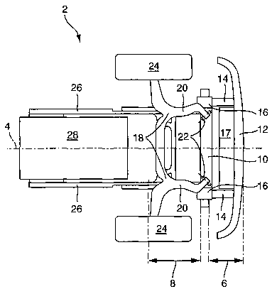
The single figure shows the substructure of a front-end
vehicle structure for a commercial vehicle in a top
view.

CA 02616050 2008-01-21
- 6 -
The front-end vehicle structure denoted as a whole by
reference 2 is configured substantially symmetrically
with respect to the longitudinal direction of the
vehicle 4.
The front-end vehicle structure 2 comprises a front
crash zone 6 and a rear crash zone 8 in the
longitudinal direction of the vehicle 4. Between the
crash zones 6 and 8 there is arranged an intermediate
structure 10 which is in the form of a cross-member and
extends substantially transversely to the longitudinal
direction of the vehicle 4.
The front crash zone 6 has a bumper 12 arranged
substantially transversely to the longitudinal
direction of the vehicle 4, the rear of which bumper
12, in the forward direction of travel, is adjoined on
the left-hand and right-hand sides by a crash box 14 in
each case. Each crash box 14 is connected to the
intermediate structure 10 via a connecting element 16.
In addition, an easily deformable radiator 17 is
arranged in the front crash zone 6.
The rear crash zone 8 is formed by chassis elements 18,
which comprise two arms 20 oriented forwardly in the
longitudinal direction of the vehicle 4 towards the
front crash zone 6. These arms 20 are each connected
via respective connecting elements 22 to the
intermediate structure 10.
The chassis elements 18 also serve for mounting the
front wheels 24 of the commercial vehicle, which is not
further illustrated.
The chassis elements 18 are connected by their rear
ends to side members 26 of a vehicle frame. The engine
28 of the commercial vehicle is accommodated between
the side members 26.

CA 02616050 2008-01-21
- 7 -
In the event of an accident with small impact forces, a
force is applied to the bumper 12 and to the adjoining
crash boxes 14. The latter are deformed while bearing
against the intermediate structure 10 via the
connecting elements 16.
In the event of an accident with relatively large
impact forces, the deformation of the front crash zone
6 is followed by the deformation of the rear crash zone
8. In this case the arms 20 are progressively buckled.
As this happens the rear crash zone 8 bears against the
side members 26 of the vehicle frame. In the event of
very large impact forces the deformation of the rear
crash zone 8 is followed by a deformation of the side
members 26 and of the engine 28.

Dessin représentatif
Une figure unique qui représente un dessin illustrant l'invention.
États administratifs

2024-08-01 : Dans le cadre de la transition vers les Brevets de nouvelle génération (BNG), la base de données sur les brevets canadiens (BDBC) contient désormais un Historique d'événement plus détaillé, qui reproduit le Journal des événements de notre nouvelle solution interne.

Veuillez noter que les événements débutant par « Inactive : » se réfèrent à des événements qui ne sont plus utilisés dans notre nouvelle solution interne.

Pour une meilleure compréhension de l'état de la demande ou brevet qui figure sur cette page, la rubrique Mise en garde , et les descriptions de Brevet , Historique d'événement , Taxes périodiques et Historique des paiements devraient être consultées.

Historique d'événement

Description Date
Demande non rétablie avant l'échéance 2010-07-12
Le délai pour l'annulation est expiré 2010-07-12
Réputée abandonnée - omission de répondre à un avis sur les taxes pour le maintien en état 2009-07-13
Lettre envoyée 2008-10-30
Inactive : Déclaration des droits - Formalités 2008-05-12
Inactive : Décl. droits/transfert dem. - Formalités 2008-04-15
Inactive : Page couverture publiée 2008-04-14
Inactive : Notice - Entrée phase nat. - Pas de RE 2008-04-10
Inactive : CIB en 1re position 2008-02-12
Demande reçue - PCT 2008-02-11
Exigences pour l'entrée dans la phase nationale - jugée conforme 2008-01-21
Demande publiée (accessible au public) 2007-02-01

Historique d'abandonnement

Date d'abandonnement Raison Date de rétablissement
2009-07-13

Taxes périodiques

Le dernier paiement a été reçu le 2008-06-19

Avis : Si le paiement en totalité n'a pas été reçu au plus tard à la date indiquée, une taxe supplémentaire peut être imposée, soit une des taxes suivantes :

  • taxe de rétablissement ;
  • taxe pour paiement en souffrance ; ou
  • taxe additionnelle pour le renversement d'une péremption réputée.

Les taxes sur les brevets sont ajustées au 1er janvier de chaque année. Les montants ci-dessus sont les montants actuels s'ils sont reçus au plus tard le 31 décembre de l'année en cours.
Veuillez vous référer à la page web des taxes sur les brevets de l'OPIC pour voir tous les montants actuels des taxes.

Historique des taxes

Type de taxes Anniversaire Échéance Date payée
Taxe nationale de base - générale 2008-01-21
TM (demande, 2e anniv.) - générale 02 2008-07-14 2008-06-19
Enregistrement d'un document 2008-09-02
Titulaires au dossier

Les titulaires actuels et antérieures au dossier sont affichés en ordre alphabétique.

Titulaires actuels au dossier
DAIMLER AG
Titulaires antérieures au dossier
MARIO LIST
WOLFGANG PEDROTTI
Les propriétaires antérieurs qui ne figurent pas dans la liste des « Propriétaires au dossier » apparaîtront dans d'autres documents au dossier.
Documents

Pour visionner les fichiers sélectionnés, entrer le code reCAPTCHA :


Pour visualiser une image, cliquer sur un lien dans la colonne description du document (Temporairement non-disponible). Pour télécharger l'image (les images), cliquer l'une ou plusieurs cases à cocher dans la première colonne et ensuite cliquer sur le bouton "Télécharger sélection en format PDF (archive Zip)" ou le bouton "Télécharger sélection (en un fichier PDF fusionné)".

Liste des documents de brevet publiés et non publiés sur la BDBC .

Si vous avez des difficultés à accéder au contenu, veuillez communiquer avec le Centre de services à la clientèle au 1-866-997-1936, ou envoyer un courriel au Centre de service à la clientèle de l'OPIC.

({010=Tous les documents, 020=Au moment du dépôt, 030=Au moment de la mise à la disponibilité du public, 040=À la délivrance, 050=Examen, 060=Correspondance reçue, 070=Divers, 080=Correspondance envoyée, 090=Paiement})


Description du
Document 
Date
(aaaa-mm-jj) 
Nombre de pages   Taille de l'image (Ko) 
Description 2008-01-20 7 300
Dessin représentatif 2008-01-20 1 8
Revendications 2008-01-20 3 94
Dessins 2008-01-20 1 14
Abrégé 2008-01-20 1 15
Rappel de taxe de maintien due 2008-04-09 1 113
Avis d'entree dans la phase nationale 2008-04-09 1 195
Courtoisie - Lettre d'abandon (taxe de maintien en état) 2009-09-07 1 172
PCT 2008-01-20 4 158
Correspondance 2008-04-09 1 25
Correspondance 2008-05-11 2 48