Note : Les descriptions sont présentées dans la langue officielle dans laquelle elles ont été soumises.
CA 02618800 2008-02-12
WO 2007/024394 PCT/US2006/029029
Hydraulic Tool Automatic Adjusting Die Holder
BACKGROUND OF THE INVENTION
Field of the Invention
[0001] The invention relates to a hydraulic tool with
a moveable member on a frame and, more particularly, to a
system for automatically adjusting the moveable member
relative to a ram which moves the moveable member
relative to the frame.
Brief Description of Prior Developments
[0002] U.S. Patent No. 2,712,252 discloses a tool for
compressing electrical connectors. A die member is
attached to an end of a ram by pins in an annular groove
and a spring. Hydraulic tools for compressing electrical
connectors or cutting electrical conductors are also
known.
[0003] In a hydraulic tool for compressing or crimping
an electrical connector onto a conductor, such as the
conventional tool 10 shown in Fig. 1, it is desirable to
keep the piston ram 12 axially aligned to the center axis
of the hydraulic cylinder 14. As seen with reference to
Fig. 2, during compression of a work piece 16, the C
shaped head 18 of the tool's working head frame 20 can
deflect or bend. If the piston ram 12 tips with the die
holder 22, the piston ram will scuff and scrape the
cylinder 14.
[0004] There is a desire to keep the piston ram
axially aligned to the hydraulic cylinder axis to prevent
the ram from tipping during compression or crimping of a
connector.
CA 02618800 2008-02-12
WO 2007/024394 PCT/US2006/029029
SUMMARY OF THE INVENTION
[0005] An automatic adjusting system can be provided
to adjust location of a die holder on a ram with both
translation of the die holder and rotation of the die
holder relative to the ram to adjust for deflection of a
tool's crimp head and thereby prevent the ram from
tipping or tilting during crimping by the tool.
[0006] In accordance with one aspect of the invention,
a hydraulic tool working head is provided including a
frame; a ram movably connected to the frame in a first
longitudinal direction, wherein the ram is adapted to be
moved relative to the frame by hydraulic fluid; and a
movable member connected to a first end of the ram by an
automatic adjusting connection. The movable member is
adapted to move relative to the ram in a second direction
perpendicular to the first direction.
[0007] In accordance with another aspect of the
invention, a hydraulic tool working head is provided
comprising a frame; a ram movably connected to the frame
in a first longitudinal direction, wherein the ram is
adapted to be moved relative to the frame by hydraulic
fluid; and a movable member connected to a first end of
the ram by an automatic adjusting connection. The
movable member is adapted to rotate along an axis
perpendicular to the first direction and translate in a
second different direction.
[0008] In accordance with one method of the invention,
a method of manufacturing a hydraulic tool working head
is provided comprising connecting a ram to a frame,
wherein the ram is adapted to be moved relative to the
frame in a first longitudinal direction by hydraulic
2
CA 02618800 2008-02-12
WO 2007/024394 PCT/US2006/029029
fluid; and connecting a movable member to a front end of
the ram with an automatic adjusting connection, wherein
the movable member is adapted to move relative to the ram
in a second direction perpendicular to the first
direction.
BRIEF DESCRIPTION OF THE DRAWINGS
[0009] The foregoing aspects and other features of the
invention are explained in the following description,
taken in connection with the accompanying drawings,
wherein:
[0010] Fig. 1 is a partial side view of a working head
in a conventional hydraulic crimping tool;
[0011] Fig. 2 is a partial side view as in Fig. 1
showing deflection of the crimpinghead during crimping
of an article;
[0012] Fig. 3 is a perspective view of a hand-held,
battery operated, hydraulic compression tool
incorporating features of the invention;
[0013] Fig. 4 is a side view of the working head of
the tool shown in Fig. 3;
[0014] Fig. 5 is a cross sectional view of the top of
the ram and the movable member shown in Fig. 4;
[0015] Fig. 6 is a cross sectional view of the top of
the ram and the movable member of an alternate embodiment
of the invention;
3
CA 02618800 2008-02-12
WO 2007/024394 PCT/US2006/029029
[0016] Fig. 7 is a cross sectional view of the top of
the ram and the movable member of an alternate embodiment
of the invention;
[0017] Fig. 8 is a cross sectional view of the top of
the ram and the movable member of an alternate embodiment
of the invention;
[0018] Fig. 9 is a cross sectional view of the top of
the ram and the movable member of an alternate embodiment
of the invention;
[0019] Fig. 10 is a cross sectional view of the top of
the ram and the movable member of an alternate embodiment
of the invention;
[0020] Fig. 11 is a cross sectional view of the top of
the ram and the movable member of an alternate embodiment
of the invention;
[0021] Fig. 12 is a cross sectional view of the top of
the ram and the movable member of an alternate embodiment
of the invention;
[0022] Fig. 13 is a perspective view of an alternate
embodiment of the thrust washer; and
[0023] Fig. 14 is a cross sectional view of another
alternate embodiment of the invention.
DETAILED DESCRIPTION OF THE PREFERRED EMBODIMENTS
[0024] Referring to Fig. 3, there is shown a
perspective view of a tool 24 incorporating features of
the invention. Although the invention will be described
with reference to the exemplary embodiments shown in the
4
CA 02618800 2008-02-12
WO 2007/024394 PCT/US2006/029029
drawings, it should be understood that the invention can
be embodied in many alternate forms of embodiments. In
addition, any suitable size, shape or type of elements or
materials could be used.
[0025] The tool 24 is a hand-held battery operated
hydraulic crimping tool. However, in alternate
embodiments, features of the invention could be used in
any suitable type of hydraulic tool or pneumatic tool, or
tool having a movable ram. The tool 24 generally
comprises a main section 26, a working head 28, and a
battery 30. In this embodiment the working head 28 is
adapted to receive removable crimp dies 32. However, in
alternate embodiments an suitable dies could be provided
including cutting dies, or the working head might have
non-removable crimping or cutting sections rather than
removable dies.
[0026] The main section 26 generally comprises an
exterior housing 34, an electric motor 36, a hydraulic
pump 38, a fluid conduit system 40 including a fluid
reservoir for conduiting fluid to and from the working
head 28, and a control system including user actuated
triggers 42, 43. In an alternate embodiment, the main
section 26 could be adapted to be connected to a remote
hydraulic fluid supply by hydraulic hoses. Yet another
embodiment may be adapted to a self contained manually
operated hydraulic crimping tool. The housing 34
comprises a handle 44. The triggers 42, 43 are mounted
on the handle. The battery 30 is removably mounted to
the bottom of the handle 44. The battery comprises a
rechargeable battery. In an alternate embodiment the
battery might not be removable or might not be
rechargeable.
CA 02618800 2008-02-12
WO 2007/024394 PCT/US2006/029029
[0027] Referring also to Fig. 4, the working head 28
generally comprises a frame 46, a ram 48, a movable
member 50 connected to the ram 48, and a spring 52. The
frame 46 comprises a first frame member 54 fixedly
connected to a frame of the fluid conduit system 40 and a
second frame member 56. The first frame member 54
comprises an inlet/outlet aperture 58 and a ram receiving
area 60. The second frame member 56 is fixedly connected
to the first frame member to substantially enclose the
ram receiving area 60 except at the aperture 58 and a ram
hole 62 through the second frame member 56. The spring
52 is located in the ram receiving area 60. The ram 48
is movably connected to the frame in a first longitudinal
direction 49, wherein the ram is adapted to be moved
relative to the frame by hydraulic fluid. The spring 52
biases the ram 48 in a retracted position as shown.
However, the bias of the spring can be overcome by
hydraulic fluid entering the area 60 from the aperture
58.
[0028] The second frame member 56 comprises a general
C shaped profile. However, in alternate embodiments
other types of shapes could be provided. The bottom end
of the C shaped profile is mounted to the first frame
member 54. The C shaped profile comprises a side
extension 64 and a top section 66. The top section 66
forms an upper die holder located opposite the ram 48.
The ram 48 is adapted to move the movable member 50
towards and away from the top section 66.
[0029] Referring also to Fig. 5, a connection 68 is
provided between the front end 70 of the ram 48 and a
rear end of the movable member 50. The connection 68 is
an automatic adjusting connection. The movable member 50
6
CA 02618800 2008-02-12
WO 2007/024394 PCT/US2006/029029
comprises a die holder for removably holding one of the
crimping dies 32. However, as noted above, the working
head might not be adapted to receive removable dies. In
that case, the movable member 50 might comprise a front
end with a crimp die shape or a cutting blade shape. The
connection 68 comprises a post 72 and a thrust washer 74.
The post 72 has a rear end located in a hole 76 at the
front end 70 of the ram 48. A nut 78 is attached to the
front end of the ram to substantially close the hole 76,
but the nut 78 has a hole 80 which a portion of the post
72 extends through. The nut 78 captures the rear end of
the post 72 in the hole 76. The hole 80 is an oversized
hole to allow the post to non-axially rotate in the hole
80. An optional spring 82 is provided to help facilitate
assembly.
[0030] The thrust washer 74 has a general domed
(partially spherical) shape with a flat bottom surface 86
which is located against the front end 70 of the ram 48.
The thrust washer 74 has a hole 88 which a portion of the
post 72 extends through. The top surface 91 of the
thrust washer 74 has a general convex shape. The front
end 84 of the post 72 is pivotably connected to the
movable member 50 by a pivot 90. The pivot 90 could
comprise a pin or fastener for example.
[00311 The movable member 50 has a rear end 92 with a
concave shaped surface 94 and a side section 96 with a
track section 98. The track section forms a lateral
guide section slideably mounted on a portion of the
frame. The surface 94 is located against the top surface
91 of the thrust washer 74. The track section 98 is
slideably interlocked with a track section 100 on the
side extension 64 of the frame 46. The movable member 50
7
CA 02618800 2008-02-12
WO 2007/024394 PCT/US2006/029029
can move up and down relative to the frame 46 with the
track section 98 sliding along the track section 100 to
retain the movable member with the frame 46. In one type
of embodiment the track sections 98, 100 comprises a
mating T shaped projection and slot. However, any
suitable shapes could be provided.
[0032] As described above with reference to Figs. 1
and 2, when exposed to the force from the ram during
crimping of a connector, the frame 46 can bend as shown
in Fig. 4. The connection 68 is adapted to allow the
movable member 50 to move relative to the ram 48 to
compensate for this deflection of the frame 46. The
movable member 50 is adapted to move relative to the ram
48 in a second direction 51 perpendicular to the first
direction 49.
[0033] It is desirable to keep the piston ram 48
axially aligned to the hydraulic cylinder axis 102. If
the piston ram 48 were to tip with the die holder 50, the
piston ram 48 would scoff and scrape the cylinder at
contact surfaces A and B. To prevent the piston ram from
tipping, the movable die holder 50 is free to translate
in the X direction as well as rotate about the Z axis.
The die holder 50 is forced to follow the head T track
100 as it deflects keeping the movable die holder free to
move relative to the ram.
[0034] Relative movement minimizes stress, wear, etc.
on the head frame 46 and movable die holder 50 T track
98. Axis 103 shows the axis of motion of the die holders
with the head loaded and deflected. Clearance between
the nut 78 and post 72, and the post 72 to the drilled
hole 76 in the hydraulic piston ram allow the die holder
8
CA 02618800 2008-02-12
WO 2007/024394 PCT/US2006/029029
50 to translate in the X direction and rotate about the
Y, Z axes. The movable die holder 50 can also rotate
about the X axis. However, when assembled to the
crimping head, the rotation about the x axis is extremely
limited as a result of the interlocking T track. The
thrust washer permits rotation about surface 94 and
translation on surface 86.
[0035] The second frame member 56 of the working head
is preferably adapted to rotate about the first frame
member 54 about the Y axis. Rotating the crimp head at
about the Y axis also causes rotation of the movable
lower die holder 50 about the Y axis. When this occurs,
it is desirable not to have the hydraulic piston ram seal
104 rotate. This device as portrayed allows the
hydraulic piston ram 48 and seal 104 to remain stationary
as the head 46 and lower die holder 50 rotate. The post
72 rotates freely within the drill hole 76 of the
hydraulic piston ram 48.
[0036] Referring now to Fig. 6, another embodiment of
the invention is shown. In this embodiment the
connection 106 between the ram 108 and the movable member
110 comprises the post 72, the nut 78, and the thrust
washer 74. The front end of the ram 108 has a concave
shaped surface 112; not a flat surface as with the ram
48. The movable member 110 has a flat bottom surface;
not a concave surface as in the movable member 50. The
thrust washer 74 is reversely orientated relative to the
position of the washer shown in Fig. S. The front end of
the post 72 is pivotably connected to the movable member
110 at pivot 90.
9
CA 02618800 2008-02-12
WO 2007/024394 PCT/US2006/029029
[0037] Referring now to Fig. 7, another embodiment of
the invention is shown. In this embodiment the
connection 114 between the ram 108 and the movable member
110 comprises the post 116 and the thrust washer 74. The
front end of the ram 108 has a concave shaped surface
112; not a flat surface as with the ram 48. The movable
member 110 has a flat bottom surface; not a concave
surface as in the movable member 50. The thrust washer
74 is reversely orientated relative to the position of
the washer shown in Fig. 5. The front end of the post
116 is pivotably connected to the movable member 110 at
pivot 90. The rear end of the post 116 is pivotably
connected to the ram 108 at pivot 118 inside the hole 76.
With this embodiment the ram would need to rotate about
the Y axis with the die holder.
[0038] Referring now to Fig. 8, another embodiment of
the invention is shown. In this embodiment the
connection 120 between the ram 48 and the movable member
50 comprises the post 116 and the thrust washer 74. The
nut 78 is not used. The front end of the post 116 is
pivotably connected to the movable member 50 at pivot 90.
The rear end of the post 116 is pivotably connected to
the ram 48 at pivot 118 inside the hole 76. This
embodiment is generally a reverse design to that shown in
Fig. 7. With this embodiment the ram would need to
rotate about the Y axis with the die holder.
[0039] Referring now to Fig. 9, another embodiment of
the invention is shown. In this embodiment the
connection 122 between the ram 108 and the movable member
124 comprises a post section 126 of the movable member
124 and the thrust washer 74. The front end of the ram
108 has a concave shaped surface 112. The movable member
CA 02618800 2008-02-12
WO 2007/024394 PCT/US2006/029029
124 has a flat bottom surface except at the post section
126. The post section 126 extends in a general
cantilever fashion from the bottom end of the movable
member 124. The thrust washer 74 is located between the
surface 112 and the bottom of the movable member with the
post section 126 extending through the hole in the thrust
washer. The rear end of the post section 126 is
pivotably connected to the ram 108 at pivot 118 inside
the hole 76. With this embodiment the ram would need to
rotate about the Y axis with the die holder.
[0040] Referring now to Fig. 10, another embodiment of
the invention is shown. In this embodiment the
connection 128 between the ram 130 and the movable member
50 comprises a post section 132 of the ram 130 and the
thrust washer 74. The front end of the ram 130 has a
flat surface except at the post section 132. The movable
member 50 has a concave shaped surface 94. The post
section 132 extends in a general cantilever fashion from
the top end of the ram 130. The thrust washer 74 is
located between the surface 94 and the top of the ram 130
with the post section 132 extending through the hole in
the thrust washer. The front end of the post section 132
is pivotably connected to the movable member 50 at pivot
90. With this embodiment the ram would need to rotate
about the Y axis with the die holder.
[0041] Referring now to Fig. 11, another embodiment of
the invention is shown. In this embodiment the
connection 134 between the ram 48 and the movable member
124 comprises a post section 126 of the movable member
124, but does not include a thrust washer. The front end
of the ram 48 has a flat shaped surface. The movable
member 124 has a flat bottom surface except at the post
11
CA 02618800 2008-02-12
WO 2007/024394 PCT/US2006/029029
section 126. The post section 126 extends in a general
cantilever fashion from the bottom end of the movable
member 124. The rear end of the post section 126 is
pivotably connected to the ram 48 at pivot 118 inside the
hole 76. With this embodiment the ram would need to
rotate about the Y axis with the die holder. This design
allows the die holder to tip. However, it does not allow
translation movement.
[0042] Referring now to Fig. 12, another embodiment of
the invention is shown. In this embodiment the
connection 136 between the ram 138 and the movable member
140 comprises a post section 142 of the movable member
140, the thrust washer 74. The front end of the ram 138
has a flat shaped surface, but with the hole 144 and the
nut 78 screwed into the hole 144. The movable member 140
has a flat bottom surface except at the post section 142.
The post section 142 extends in a general cantilever
fashion from the bottom end of the movable member 140.
The post section 142 extends through the hole in the
thrust washer. The rear end of the post section 126 has
a threaded hole 146. The connection 136 also comprises a
fastener 148. The fastener 148 is screwed into the
threaded hole 146. The fastener 148 has an enlarged
section located behind the nut 78 to thereby retain the
movable member 140 with the ram 138.
[0043] Referring also to Fig. 13, an alternate
embodiment of the thrust washer is shown. In this
embodiment the thrust washer 150 has flat side surfaces
152 and a flat bottom surface 154, but a curved top
surface 156. In another alternate embodiment, the domed
thrust washer and the nut could be combined into a single
member.
12
CA 02618800 2008-02-12
WO 2007/024394 PCT/US2006/029029
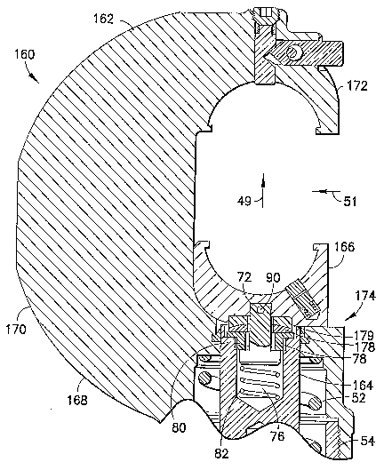
[0044] Referring now to Fig. 14, another embodiment is
shown. In this embodiment the hydraulic tool working
head 160 comprises a frame 162, a ram 164, a movable
member 166 connected to the ram 164, and a spring 52.
The frame 162 comprises a first frame member 54 fixedly
connected to a frame of the fluid conduit system of the
rest of the tool and a second frame member 168. The
second frame member 168 comprises a general C shaped
profile. However, in alternate embodiments other types
of shapes could be provided. The bottom end of the C
shaped profile is mounted to the first frame member 54.
The C shaped profile comprises a side extension 170 and a
top section 172. The top section 172 forms an upper die
holder located opposite the ram 164. The ram 164 is
adapted to move the movable member 166 towards and away
from the top section 172.
[0045] A connection 174 is provided between the front
end of the ram 164 and a rear end of the movable member
166. The connection 174 is an automatic adjusting
connection. The movable member 166 comprises a die
holder for removably holding one of the crimping dies 32
(see Fig. 3). However, as noted above, the working head
might not be adapted to receive removable dies. In that
case, the movable member might comprise a front end with
a crimp die shape or a cutting blade shape. The
connection 174 comprises a post 72 and a pair of thrust
washers 178, 179. The front end of the post 72 is
pivotably connected to the movable member 166 by a pivot
90. The pivot 90 could comprise a pin or fastener for
example. The post 72 has a rear end located in a hole 76
at the front end of the ram 164. A nut 78 is attached to
the front end of the ram to substantially close the hole
13
CA 02618800 2008-02-12
WO 2007/024394 PCT/US2006/029029
76, but the nut 78 has a hole 80 which a portion of the
post 72 extends through. The nut 78 captures the rear
end of the post 72 in the hole 76. The hole 80 is an
oversized hole to allow the post to non-axially rotate in
the hole 80. The post 72 can also axially rotate in the
hole 80. An optional spring 82 is provided to help
facilitate assembly.
[0046] The pair of thrust washers 178, 179 are two-
piece spherical washers, such as made of steel or
stainless steel. The bottom washer 178 has a flat bottom
side and a dome shaped top side. The bottom side of the
bottom washer 178 can sit on the top side of the nut 78.
The top washer 179 has a flat top side and a concave
shaped bottom side. The bottom side of the top washer
179 is sized and shaped to mate with the dome shaped top
side of the bottom washer 178. The bottom of the movable
member 166 can have a recess to receive and seat the top
side of the top washer 179. Preferably, both the ram and
the movable member are counter-bored. The function is
still the same because the lower spherical washer can
still translate and allows the movable member to rotate.
Two-piece spherical washers can be purchased as off-the-
shelf items, thereby making the working head 160 less
expensive to manufacture.
[0047] As described above with reference to Figs. 1
and 2, when exposed to the force from the ram during
crimping of a connector, the frame can bend. The
connection 174 is adapted to allow the movable member 166
to move relative to the ram 164 to compensate for this
deflection of the frame 162. The movable member 166 is
adapted to translate relative to the ram 165 in a second
14
CA 02618800 2008-02-12
WO 2007/024394 PCT/US2006/029029
direction 51 perpendicular to the first direction 49, as
well as rotate relative to the ram.
[0048] It should be understood that the foregoing
description is only illustrative of the invention.
Various alternatives and modifications can be devised by
those skilled in the art without departing from the
invention. Accordingly, the invention is intended to
embrace all such alternatives, modifications and
variances which fall within the scope of the appended
claims.