Note : Les descriptions sont présentées dans la langue officielle dans laquelle elles ont été soumises.
CA 02620286 2008-02-25
WO 2007/027682 PCT/US2006/033696
VARIABLE RELUCTANCE POSITION SENSOR AND METHOD FOR
DETERMINING A POSITION OF A ROTATING BODY
Inventors: SAGOO, Bahadur, TCHAKAROV, Borislav W., and PHAN,
Quan
BACKGROUND
Hall Effect sensors have been developed to detect a rotational position of a
motor. A problem associated witli Hall Effect sensors, is that when the Hall
Effect
sensors are utilized in operating environments with a relatively higli
operating
temperature (e.g., 350 F), the output signals from the sensors can become
degraded.
[0001] Further, position measuring circuits that measure the back emf voltage
in motor coils to determine a rotational position of a motor have been
developed. A
problem associated with these circuits that are electrically coupled to the
motor, is that
at relatively high operating temperatures, the circuits output signals having
a
relatively low signal-to-noise ratio which may not provide an accurate
indication of
the rotational position of the motor.
Accordingly, the inventors herein have recognized a need for an improved
position sensor that is electrically isolated from a motor that can generate
signals
indicative of a rotational position of the motor.
SUMMARY
[0002] A variable reluctance position sensor for sensing a position of a
rotating body in accordance with an exemplary embodiment is provided. The
variable
reluctance position sensor includes a rotatable member configured to be
operably
coupled to the rotating body. The rotatable member has a first non-magnetic
body
portion and a plurality of magnets disposed equidistant from one another
around an
exterior region of the first non-magnetic body portion. The variable
reluctance
position sensor further includes a stator assembly having a second non-
magnetic body
portion with an aperture extending theretlirough for receiving the rotatable
member
therein. The stator assenibly further includes a plurality of coils and a
plurality of coil
CA 02620286 2008-02-25
WO 2007/027682 PCT/US2006/033696
35 brackets. Each coil of the plurality of coils is attached to a respective
coil bracket of
the plurality of coil brackets. The plurality of coil brackets is fixedly
attached
equidistant froin one another to the second non-magnetic body portion.
Rotation of
the rotatable member induces the plurality of coils to generate voltage
signals
indicative of a position of the rotatable member.
[0003] A method for determining a position of a rotating body utilizing a
variable reluctance position sensor in accordance with another exemplary
embodiment is provided. The variable reluctance position sensor comprises a
rotatable member configured to be operably coupled to a rotating body. The
rotatable
member has a first non-magnetic body portion and a plurality of magnets
disposed
equidistant from one another around an exterior region of the first non-
magnetic body
portion. The variable reluctance position sensor further comprises a stator
assembly
having a second non-magnetic body portion with an aperture extending
therethrougli
for receiving the rotatable member therein. The stator assembly further
includes a
plurality of coils and a plurality of coil brackets. Each coil of the
plurality of coils is
attached to a respective coil bracket of the plurality of coil brackets. The
plurality of
coil brackets are fixedly attached equidistant from one another to the second
non-
magnetic body portion. The method includes rotating the rotatable member of
the
variable reluctance position sensor in response to rotation of the rotating
member
coupled to rotatable member, wherein the plurality of magnets on the rotatable
member are rotated past the plurality of coils of the stator assembly of the
variable
reluctance position sensor to induce the plurality of coils to generate
voltage signals.
The method further includes measuring the generated voltage signals to
determine the
position of the rotata.ble member utilizing a controller.
65
2
CA 02620286 2008-02-25
WO 2007/027682 PCT/US2006/033696
BRIEF DESCRIPTION OF THE DRAWINGS
[0004] Figure 1 is a block diagram of a core extraction system having a coring
apparatus for obtaining a sidewall core from an earth formation, in accordance
with an
exemplary embodiment;
[0005] Figure 2 is a cross-sectional view of a portion of the rotary coring
device utilized in the coring apparatus of Figure 1;
[0006] Figure 3 is a side view of a portion of the rotary coring device
utilized
in the coring apparatus of Figure 1;
[0007] Figure 4 is an isometric view of a portion of a rotary coring device
utilized in the coring apparatus of Figure 1;
[0008] Figure 5 is a schematic of the rotary coring device disposed in a
wellbore;
[0009] Figure 6 is a schematic of a 1lydraulic control system and liydraulic
actuators for moving a coring tool of the rotary coring device to a desired
position
within a wellbore;
[0010] Figure 7 is an isometric view of the coring tool utilized in the rotary
coring device;
[0011] Figure 8 is a side view of a portion of the rotary coring device in a
first
operational position within the wellbore;
[0012] Figure 9 is a side view of the portion of the rotary coring device in a
second operational position within the wellbore;
100 [0013] Figure 10 is a side view of the portion of the rotary coring device
in a
third operational position within the wellbore;
3
CA 02620286 2008-02-25
WO 2007/027682 PCT/US2006/033696
[0014] Figure 11 is a side view of the variable reluctance position sensor
utilized in the rotary coring device, in accordance with an exemplary
embodiment;
105 [0015] Figure 12 is an isometric view of a rotor utilized in the variable
reluctance position sensor of Figure 11;
[0016] Figure 13 is a cross-sectional view of the variable reluctance position
sensor of Figure 11;
110
[0017] Figure 14 is a cross-sectional view of the variable reluctance position
sensor of Figure 13 taken along lines 14-14;
[0018] Figure 15 is a cross-sectional view of the variable reluctance position
115 sensor-of Figure 13 taken along lines 15-15; and
[0019] Figure 16 is an electrical schematic of a position sensing system
utilized in the core extraction system of Figure 1.
120 [0020] Figures 17-19 are schematics of position signals generated by the
variable reluctance position sensor of Figure 11.
DETAILED DESCRIPTION OF EXEMPLARY EMBODIMENTS
125 Referring to Figure 1, a core extraction system 10 for obtaining a
sidewall core
from an earth formation 20 adjacent a wellbore is provided. The core
extraction 10
includes a coring apparatus 12, a hoist 14, and a controller 16.
[0021] The coring apparatus 12 is disposed at selected depths within the
130 wellbore 18 of the earth fomiation 20 via a wireline 22 coupled to the
hoist 14. The
coring apparatus 12 is configured to acquire at least one sidewall core of a
portion of
the earth formation proximate the wellbore 18 at a predetermined depth. The
coring
apparatus 12 includes an electro-hydraulic section 30, a rotary coring device
32, and a
core receptacle section 34.
4
CA 02620286 2008-02-25
WO 2007/027682 PCT/US2006/033696
135 [0022] The electro-hydraulic section 30 is provided to house electrical
components and circuits for controlling the extension and retraction of
locking arms
40, 41 in response to control signals from the controller 16. In particular,
the electro-
hydraulic section 30 extends the locking arms 40, 41 in an outwardly direction
to
move the coring apparatus 12 adjacent a wall of the wellbore 18 for obtaining
a
140 sidewall core. Alternately, the electro-hydraulic section 30 retracts the
loclcing arms
40, 41 to move the coring apparatus 12 away from the wall. The electro-
hydraulic
section 30 further includes a hydraulic control system 40, wliich will be
described in
further detail below.
145 [0023] Referring to Figures 1-5, the rotary coring device 32 is provided
to
acquire sidewall cores from the earth formation 20. The rotary coring device
32
includes an electrical motor 50, a transmission assembly 52, a position
sensing system
54, a coring tool 56, hydraulic actuators 58, 60, shafts 62, 64, guide plates
66, 68,
pivot arms 70, 72, hydraulic actuators 74, 76, connecting arms 78, 80, and a
core
150 ejecting shaft 82.
[0024] Referring to Figure 2, the electrical motor 50 is provided to drive a
gear assembly in the coring tool 56 for rotating a rotary coring bit 130 at
one of a
plurality of rotational speeds. In an exemplary embodiment, the electrical
motor 50
155 comprises a DC electrical motor. It should be noted, however, that in
other
exemplary embodiments, the electrical motor 50 can comprise any other motor
known
to those skilled in the art, such as a variable reluctance motor or a switched
reluctance
motor for example. The electrical motor 50 includes a stator (not shown) and a
rotor
90 that rotates at one of a plurality of rotational speeds, in response to
commutation
160 signals from the controller 16. For example, the controller 16 can
generate
commutation signals for inducing the electrical motor 50 to rotate at a first
predetermined rotational speed in response to a predetermined parameter of the
earth
formation 20 at a first predetermined depth. Further for example, the
controller 16
can generate commutation signals for inducing electrical motor 50 to rotate at
a
165 second predetermined rotational speed greater than the first predetermined
speed, in
response to a predetermined parameter of the earth formation 20 at a second
predetermined depth. As shown, the electrical motor 50 is operably coupled to
the
CA 02620286 2008-02-25
WO 2007/027682 PCT/US2006/033696
transmission assembly 52. In particular, the rotor 90 of the motor 50 is
operably
coupled to a connecting member 100 of the transmission assembly 52.
170
Referring to Figures 2 and 4, the transmission assembly 50 is provided to
transfer torque from the motor 52 to a gear assembly in the coring tool 56.
The
transmission assembly 52 includes housing portions 96, 98, a coupling member
100, a
drive shaft 102, a bevel gear 104, and a pinion gear 106. The housing portions
96,
175 98 are operably coupled together and define an interior region for
enclosing the
remaining components of the transmission assembly 52. The coupling member 100
is
operably coupled at first end to the rotor 90 of the motor 50. Further, the
coupling
member 100 is operably coupled at a second end to a first end of the drive
shaft 102.
A second end of the drive shaft 102 is fixedly attached to the bevel gear 104.
Thus,
180 rotation of both the rotor 90 induces rotation of the drive shaft 102 and
the bevel gear
104. The bevel gear 104 is operably coupled to the pinion gear 106. Thus,
rotation of
the bevel gear 100 induces rotation of the pinion gear 106.
Referring to Figures 4 and 7, the coring tool 56 is provided for extracting a
185 sidewall core from the eartli formation 20. The coring tool 56 includes a
housing 120,
a gear assembly comprising a gear 122 and a gear 124, a movable plate 126, a
pair of
guide pins 128 (one being shown), a pair of guide pins 129 (one being shown),
and a
rotary coring bit 130. The housing 120 defines an interior region for holding
the gear
122, the gear 124, and the movable plate 126. When the coring tool 56 is moved
to an
190 operational position where the pinion gear 106 of the transmission
assembly 52
engages the gear 122, rotation of the pinion gear 106 induces rotation of the
gear 122.
Further, rotation of the gear 122 induces rotation of the gear 124 and the
rotary coring
bit 130. The movable plate 128 is movable along an axial direction of the
rotary
coring bit 130. The guide pins 128 are disposed on opposite sides of the
movable
195 plate 128 and are provided for the guiding movement of the rotary coring
bit 130 in a
linear direction (either outwardly or inwardly with respect to the housing
120) as will
be explained in further detail below. The guide pins 129 are disposed on
opposite
sides of the housing 120 and are also provided for guiding movement of the
rotary
coring bit 130 in a linear direction (either outwardly or inwardly with
respect to the
200 housing 120) as will be explained in furtlier detail below.
6
CA 02620286 2008-02-25
WO 2007/027682 PCT/US2006/033696
Referring to Figure 5, as discussed above, the rotary coring device 32
includes
hydraulic actuators 58, 60. The hydraulic actuators 58, 60 are provided to
move the
coring tool 56 to desired operational positions within the wellbore 18. The
hydraulic
actuators 58, 60 are configured to extend and retract piston shafts 62, 64,
respectively.
205 The shafts 62, 64 are further coupled to the guide plates 66, 68,
respectively.
Referring to Figures 5 and 7, the guide plates 66, 68 are provided to guide
movement of the coring too156. The guide plate 66 includes cam slots 140, 142
extending therethrough. The cam slots 140, 142 are provided receive therein
guide
210 pins 128, 129 on a first side of the coring tool 56. The guide plate 68
includes cam
slots 144, 146 extending therethrough. The cam slots 144, 146 are provided to
receive therein guide pins 128, 129 on a second side of the coring too156.
Referring to Figures 5 and 8, the remaining components of the rotary coring
215 device 32 will now be explained. The pivot arms 70, 72 are operably
coupled to the
housing 120 of the coring too156. The pivot arm 70 has an elongated portion
160 and
a U-shaped portion 162. The elongated portion 160 is connected at a first end
to the
housing 120. The elongated portion 160 is connected at a second end to the
connecting arm 78. The U-shaped portion 162 extends outwardly from the
elongated
220 portion 160 and is configured to allow movement of the pivot arm 70
relative to a
stationary pin. The pivot arm 72 has an elongated portion 164 and a U-shaped
portion
166. The elongated portion 164 is connected at a first end to the housing 120.
The
elongated portion 164 is connected at a second end to the connecting arm 80.
The U-
shaped portion 166 extends outwardly from the elongated portion 164 and is
225 configured to allow movement of the pivot arm 72 relative to a stationary
pin. The
hydraulic actuators 74, 76 are operably coupled to the connecting arms 78, 84
respectively, controlling movement of the coring tool 56. In particular,
hydraulic
actuators 74, 76 retract or extend the connecting arms 78, 80, respectively,
to move
the coring too156. The core injecting shaft 82 is utilized to contact a
sidewall core
230 contained within the coring tool 56 for ejecting the core from the coring
too156 into
the core receptacle section 34 when the coring too156 is disposed in an
upright
position in the wellbore 18 as shown in Figure 8.
7
CA 02620286 2008-02-25
WO 2007/027682 PCT/US2006/033696
Referring to Figure 8, positioning of the coring too156 for acquiring a
sidewall
core will now be explained. Initially, as shown, the coring too156 is disposed
beneath
235 the transmission assembly 52 in the wellbore 18. Referring to Figures 6
and 9,
thereafter, the controller 16 outputs command signals to the hydraulic control
system
40. The command signals induce the hydraulic control system 42 to induce the
hydraulic actuators 58, 60 to urge the guide plates 66, 68, respectively,
upwardly
which causes the rotary coring tool 56 to rotate such that the rotary coring
bit 130 is
240 moved outwardly from the housing 120 of the coring too156. In particular,
the guide
pins 128, 129 on a first side of the rotary coring tool 56 move within the cam
slots
140, 142. Concurrently, the guide pins 128, 129 on a second side of the rotary
coring
too156 move within the cam slots 144, 146 on the guide plate 68. Referring to
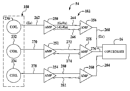
Figure
10, when the hydraulic actuators 58, 60 urge the guide plates 66, 66 to a
245 predetermined extended position, the gear 106 of the transmission assembly
52 is
operably coupled to the gear 122 of the coring too156, for transmitting torque
to the
gear 122. Further, the guide pins 128 attached to the movable plate 126 urge
the
movable plate 126 outwardly (rightwardly in Figure 10) such that the rotary
coring bit
130 contacts a portion of the earth formation 20. Thereafter, the controller
16
250 generates commutation signals to induce the motor 50 to rotate the rotary
coring bit
130 for acquiring a sidewall core.
Referring to Figures 13-16, the position sensing system 54 is provided to
generate position signals indicative of a rotational position of the rotor 90
of the motor
255 50. The signals generated by the position sensing system 54 are received
by the
controller 16 and the controller 16 generates commutation signals for
controlling
operation of the motor 50, in response to the position signals. The position
sensing
system 54 includes the variable reluctance position sensor 180 and the
amplifier
circuit 182.
260
Referring to Figures 11-15, the variable reluctance position sensor 180 is
configured to be mechanically coupled to the rotor 90 of the motor 50 for
generating
voltage signals indicative of a position of the rotor 90. An advantage of the
variable
reluctance position sensor 180 is that the sensor is not electrically coupled
to the
265 motor 50, thus eliminating electrical noise generated by the motor 50,
from position
8
CA 02620286 2008-02-25
WO 2007/027682 PCT/US2006/033696
signals generated by the sensor 180. A further advantage of the variable
reluctance
position sensor 180 is that the sensor 180 can generate accurate position
signals when
operating at relatively high temperatures. The variable reluctance position
sensor 180
includes a housing 190, a rotor 192, magnets 194, 196, 198, 200, 202, 204,
206, 208,
270 and a stator assembly 210.
The housing 190 is provided to enclose the remaining components of the
variable reluctance position sensor 180. The housing 190 is constructed from a
non-
magnetic material, such as aluminum for example.
275
The rotor 192 is positioned within an aperture defined by the stator assembly
210. The rotor 192 is generally cylindrical-shaped and is constructed from a
non-
magnetic material, such as plastic for example. The rotor 192 includes a first
plurality
of apertures extending from an outer surface of the rotor 192 inwardly into
the rotor
280 192, for receiving magnets 194, 196, 198, and 200 therein. The magnets
194, 196,
198, and 200 are disposed at positions 90 apart from one another about an
axis 201,
at a first predetermined axial position along the rotor 192. The rotor 192
includes a
second plurality of apertures extending from the outer surface of the rotor
192
inwardly into the rotor 192, for receiving magnets 202, 204, 206, 208 therein.
The
285 magnets 202, 204, 206, 208 are disposed at positions 90 apart from one
another
about the axis 201, at a second predetermined axial position along the rotor
192. The
magnets 202, 204, 206, 208 are offset 45 degrees from magnets 194, 196, 198,
and
200 about the axis 201. The rotor 192 further includes an aperture 193
extending
from a first end of the rotor 192 inwardly into the rotor 192 a predetermined
distaiice.
290 The aperture 193 is configured to receive an end of the rotor 90 of the
motor 50 for
fixedly coupling the rotor 192 to the rotor 90. Thus, the rotor 192 rotates at
a
substantially similar speed as the rotor 90 of the motor 50. Further, the
magnets may
comprise rare-earth magnets.
295 The stator assembly 210 includes a non-magnetic body portion 212, coil
brackets 214, 216, 218 and coils 230, 232, 234. The non-magnetic body portion
212
is generally ring-shaped and has an aperture extending therethrough with a
diameter
larger than an outer diameter of the rotor 192. In other words, a small air
gap is
9
CA 02620286 2008-02-25
WO 2007/027682 PCT/US2006/033696
defined between an outer surface of the rotor 192 and inner surface defined by
the
300 non-magnetic body portion 212. The coil brackets 214, 216, 218 are
provided to
fixedly hold the coils 230, 232, 234, respectively thereon. The coil brackets
214, 216,
218 are configured to be disposed in apertures extending into an exterior
surface of
the non-magnetic body portion 212. The coil brackets 214, 216, 218 are
disposed at
positions 120 apart from one another about the axis 201. Further, the coil
brackets
305 214, 216, 218 are constructed from carbon steel for concentrating magnetic
flux from
the rotor magnets around the coils 230, 232, 234, respectively.
The operation of the variable reluctance position sensor 180 will now be
explained. The sensor 180 utilizes an interaction between electromagnetic
fields
310 generated by the magnets on the rotor 192 and electrical currents
generated in the
coils 230, 232, 234 in response to the electromagnetic fields nioving past the
coils
230, 232, 234 when the rotor 192 is rotating. Faraday's Law of electromagnetic
induction, states that a voltage (i.e., an electro-magnetic force EMF) is
induced in a
conductor such as a coil, when magnetic flux lines are at a right angle with
respect to
315 the conductor. Thus, in particular, when a magnet moves past a coil having
a length
(L), a number of turns (N) and a cross-sectional area (A)--at a velocity (w)
radians per
second, and the magnetic field (B) generated by the magnet moves at a right
angle
uniformly past the conductor, a voltage (E) is induced in the coil that is
described by
the following equation:
320 E = BNLAw sin (wt)
Furtlier, because the coils 230, 232, 234 are displaced from each other
by 120 , the voltages (Ea), (Eb), (Ec) generated in the coils 230, 232, 234,
respectively by rotation of the magnets on the rotor 192 are described by the
following equations:
325 Ea = BNLAw sin (wt)
Eb = BNLAw sin (wt - 120 )
Ec = BNLAw sin (wt - 240 ).
Referring to Figure 17, an exemplary voltage waveforin 236
representing the voltage (Ea) generated by the coil 230 over time is
illustrated.
330 Further, referring to Figure 18, an exemplary voltage waveform 238
representing the
voltage (Eb) generated by the coil 232 over time is illustrated. Further,
referring to
CA 02620286 2008-02-25
WO 2007/027682 PCT/US2006/033696
Figure 19, an exemplary voltage waveform 240 representing the voltage (Ec)
generated by the coil 234 over time is illustrated.
335 The relationship between the electrical position and the mechanical
position of
the rotor 192 of the variable reluctance position sensor 180 is determined
utilizing the
following equation:
Oe = (Pr/2) * Om
where:
340 Oe corresponds to an electrical degree position of the rotor 192 for
magnetic orientation;
Om corresponds to a mechanical degree position of the rotor 192; and
Pr corresponds to a number of magnets on the rotor 192.
345 The relationship between the mechanical and electrical speeds of the rotor
192
is determined utilizing the following equation:
coe = Pr/2 * eom
where:
coe corresponds to an electrical speed in radians per seconds (or RPM)
350 of the rotor 192;
wm corresponds to a mechanical speed in radians per second (or RPM)
of the rotor 192.
Referring to Figure 16, the amplifier circuit 182 for amplifying and filtering
355 out noise in the voltages (Ea), (Eb), and (Ec) is illustrated. The
amplifier circuit 182
includes differential amplifiers 250, 252, 254, noise cancellation amplifiers
256, 258,
260, and conductors 262, 264, 266, 268, 270, 272, 274, 276, 278, 280, 282, and
284.
[0025] The coil 230 is electrically coupled to an input terminal of the
360 amplifier 250 via the conductor 262. The amplifier 250 has first and
second output
terminals electrically coupled to first and second terminals of the amplifier
256 via the
conductors 264, 266, respectively. An output terminal of the amplifier 256 is
electrically coupled to the controller 16 via the conductor 268. During
operation, the
amplifier 250 receives the voltage (Ea) from the coil 230 and outputs an
amplified
11
CA 02620286 2008-02-25
WO 2007/027682 PCT/US2006/033696
365 voltage (G*Ea) on the conductor 264 and an amplified voltage (-G*Ea) on
the
conductor 266, where G corresponds to a predetermined voltage gain. The noise
cancellation amplifier 256 outputs the voltage (Ea'), having less electrical
noise than
voltage (Ea), in response to receiving the voltages (G*Ea) and (-G*Ea). The
voltage
(Ea') which is indicative of the position of the rotor 90 is received by the
controller
370 16.
The coil 232 is electrically coupled to an input terminal of the amplifier 252
via the conductor 270. The amplifier 252 has first and second output terminals
electrically coupled to first and second terminals of the amplifier 258 via
the
375 conductors 272, 274, respectively. An output terminal of the amplifier 258
is
electrically coupled to the controller 16 via the conductor 276. During
operation, the
amplifier 252 receives the voltage (Eb) from the coil 232 and outputs an
amplified
voltage (G*Eb) on the conductor 272 and an amplified voltage (-G*Eb) on the
conductor 274, where G corresponds to the predetermined voltage gain. The
noise
380 cancellation amplifier 258 outputs the voltage (Eb'), having less
electrical noise than
voltage (Eb), in response to receiving the voltages (G*Eb) and (-G*Eb). The
voltage
(Eb') whicli is also indicative of the position of the rotor 90 is received by
the
controller 16.
385 The coil 234 is electrically coupled to an input terminal of the amplifier
254
via the conductor 278. The amplifier 254 has first and second output terminals
electrically coupled to first and second terminals of the amplifier 260 via
the
conductors 280, 282, respectively. An output terminal of the amplifier 260 is
electrically coupled to the controller 16 via the conductor 284. During
operation, the
390 amplifier 254 receives the voltage (Ec) from the coil 234 and outputs an
amplified
voltage (G*Ec) on the conductor 280 and an amplified voltage (-G*Ec) on the
conductor 282, where G corresponds to the predetermined voltage gain. The
noise
cancellation amplifier 260 outputs the voltage (Ec'), having less electrical
noise than
voltage (Ec), in response to receiving the voltages (G*Ec) and (-G*Ec). The
voltage
395 (Ec') which is indicative of the position of the rotor 90 is received by
the controller
16.
12
CA 02620286 2008-02-25
WO 2007/027682 PCT/US2006/033696
Referring again to Figure 1, the controller 16 is provided to control
operation
of the coring apparatus 12 and the hoist 14. In particular, the controller 16
generates
control signals for controlling operation of the hoist 14 for positioning the
rotary
400 coring device 32 at predetermined depths within the welibore 18. Further,
the
controller 16 generates control signals for controlling operation of the
hydraulic
control system 44 for orientating the coring too156 of the rotary coring
device 32
within the wellbore 20 for acquiring a sidewall core. Further, the controller
16
generates control signals for controlling operation of the motor 50 utilized
in the
405 rotary coring device 32 for driving the rotary coring bit 130. Further,
the controller
16 receives the position voltages (Ea') (Eb'), (Ec') from the position sensing
system 54
and utilizes the position voltages for controlling operation of the motor 50.
The variable reluctance position sensor and the method for determining a
410 position of rotating body provide a substantial advantage over other
sensors and
methods. In particular, the variable reluctanee position sensor is
electrically isolated
from a motor and can generate position signals indicative of a rotational
position of a
motor rotor without substantial electrical noise from the motor. Further, the
variable
reluctance position sensor can generate accurate position signals of the rotor
when
415 operating at a relatively high temperatures (e.g., greater than 350
degrees Fahrenheit).
The above-described methods can be embodied in the form of computer-
implemented processes and apparatuses for practicing those processes. In an
exemplary embodiment, the method is embodied in computer program code executed
420 by the computer or controller. The method may be embodied in the form of
computer
prograin code containing instructions embodied in tangible media, such as
floppy
diskettes, CD-ROMs, hard drives, or any other computer-readable storage
medium,
wherein, when the computer program code is loaded into and executed by a
controller, the controller becomes an apparatus for practicing the invention.
425
The terms "first," "second," and the lilce, herein do not denote any order,
quantity, or importance, but rather are used to distinguish one element from
another,
and the terms "a" and "an" herein do not denote a limitation of quantity, but
rather
denote the presence of at least one of the referenced item. Unless defined
otherwise,
13
CA 02620286 2008-02-25
WO 2007/027682 PCT/US2006/033696
430 technical and scientific terms used herein have the same meaning as is
commonly
understood by one of slcill in the art to which this invention belongs.
[0026] While the invention has been described with reference to an exemplary
embodiment, it will be understood by those skilled in the art that various
changes may
435 be made and equivalents may be substituted for elements thereof without
departing
from the scope of the invention. In addition, many modifications may be made
to
adapt a particular situation or material to the teachings of the invention
without
departing from the essential scope thereof. Therefore, it is intended that the
invention
not be limited to the particular einbodiment disclosed as the best mode
contemplated
440 for carrying out this invention, but that the invention will include all
embodiments
falling within the scope of the appended claims.
14