Note : Les descriptions sont présentées dans la langue officielle dans laquelle elles ont été soumises.
CA 02621225 2008-02-29
1
LASER MARKING SYSTEM FOR GEMSTONES AND METHOD OF
AUTHENTICATING MARKING
FIELD OF THE INVENTION
The present invention relates to the field of inscribing indicia on a surface
of
gemstones, and more particularly to a system employing a Q-switched pulse
laser for
forming markings on a portion of a gemstone.
BACKGROUND OF THE INVENTION
A known system, as described in U.S. Patent No. 4,392,476 for inscribing
diamonds includes a Nd:YAG (1.06 m, frequency doubled) Q- switched laser
which
marks diamonds by graphitizing the surface at a laser focal point. The beam
position is
computer controlled to create overlapping treated regions. The accuracy of
known
embodiments of this system are limited by vibration and laser steering system
accuracy.
U.S. Patent No. 4,467,172 describes a laser beam diamond inscribing system,
which provides a Q-switched flashlamp pumped YAG laser (1.06 gm, frequency
doubled) with the diamond mounted on a computer-controlled positioning table
for
inscribing alphanumeric characters. See also, U.S. Patent Nos. 2,351,932,
3,407,364,
3,527,198, 3,622,739, 3,775,586 and 4,048,515, and foreign patents JP 00-
48,489 and JP
00-77,989.
U.S. Patent Nos. 5,410,125 and 5,149,938 describe systems which produce a
gemstone marking by employing an excimer laser (193 nm) with a masked marking
image. Thus, repositioning to form complete characters or graphics is
unnecessary. The
diamond selectively absorbs the excimer laser radiation and undergoes a
partial allotropic
transformation without losing its diamond crystal lattice configuration. See
also, U.S.
Patent Nos. 3,527,198 and 4,401,876. US Patent No. 5,410,125 is a continuation-
in-part
of Ser. No. 595,861, issued as Pat. No. 5,149,938.
CA 02621225 2008-02-29
2
Gemstone News, 11/2/95, "Serial Numbers are Laser Inscribed", and Jeweler's
Keystone-Circular, June 1996, pp. 76 relate to gemstones inscribed with serial
numbers
or markings.
U.S. Patent No. 3,537,198 relates to a method of working diamonds using laser
energy. US Patent No. 5,190,024, relates to a diamond sawing process. A laser
can be
used both to mark and saw the diamond in one operation. See also, U.S. Patent
Nos.
671,830, 671,831, 694,215, 732,118, 732,119, 3,527,198 and 4,392,476, as well
as
Foreign Reference GB 122,470.
U.S. Patent No. 4,401,876 relates to a system for kerfing a gemstone such as a
diamond, employing a high energy, high pulse rate, low order mode, laser beam.
See
also, U. S. Patent Nos. 3,440,388, 3,527, 198 and 3,700,850, as well as
foreign references
BE 877,326, DE 130,138, DE 133,023, GB 1,057,127, GB 1,059,249, GB 1,094,367,
GB
1,254,120, GB 1,265,241, GB 1,292,981, GB 1,324,903, GB 1,326,775, GB
1,377,131,
GB 1,405,487, GB 1,446,806, GB 2,052,369, Laser Institute of America, "Guide
for
Material Processing by Lasers" 1978; "Industrial Diamond Review", Mar. 1980,
pp. 90
and 91; "Laser Application Notes", 1(1) (Feb. 1979); "New Hyperyag", on Model
DLPY
4-System 2000 Yag Laser; and "Diamonds": N.A.G. Press LTD, Chapter Eleven, pp.
235, 239-242.
U.S. Patent No. 4,799,786 relates to a method of diamond identification
provides
a method for the identification of diamonds in which a sample to be identified
is placed in
a beam of monochromatic laser radiation of pre-determined wavelength. The
scattered
Raman radiation emitted from the sample is passed through a filter adapted to
pass only
scattered Raman radiation of frequency characteristic of a diamond. The
filtered radiation
is then detected by the human eye or a photocell device. See also, U.S. Patent
Nos.
4,397,556 and 4,693,377, and foreign patent GB 2,140,555, Melles Griot, Optics
Guide 3,
1985, pp. 1, 333, 350, 351; and Solin et al., Physical Review B, 1(4): 1687-
1698 (Feb. 15,
1970).
CA 02621225 2008-02-29
3
U.S. Patent No. 4,875,771 relates to a method for assessing diamond quality,
by
assessing diamonds with a laser Raman spectrometer. The system is initially
calibrated
by use of diamonds with known quality characteristics, the characteristics
having been
assessed, for example, by a conventional subjective procedure. Diamonds of
unknown
quality characteristics are then placed in the spectrometer and irradiated
with laser
radiation. The intensity of the scattered Raman signal from the diamond is
monitored for
one or more orientations of the diamond, the resultant signal being a
characteristic of the
diamond and believed to indicate a quality level of the diamond. See also,
U.S. Patent
Nos. 3,414,354, 3,989,379, 4,259,011, 4,394,580, 4,397,556 and 4,620,284, and
foreign
patents FR 643,142, FR 2,496,888, JP 01-58,544, GB 1,384,813, GB 1,416,568, GB
2,010,474, GB 0,041,348 and GB 2,140,555, S. A. Solin and K. A. Ramdas, Raman
Spectrum of Diamond, Physical Review vol. 1(4), pp. 1687-1698.
The aforementioned documents detail components, methods and systems which
may be applied in the construction and operation of the present invention.
SUMMARY OF THE INVENTION
The present invention provides a system having a pulse laser, such as a Q-
switched laser diode excited Nd:YLF laser, which produces a series of ablated
or
graphitized spots on the surface of a workpiece, such as a diamond gemstone.
The
workpiece is mounted on a translatable stage, for focusing and positioning of
the beam.
The translatable stage is controlled by a computer to produce a complex
marking
pattern. This computer may also be used for process control and imaging, as
well as other
functions.
The process according to the present invention typically achieves a
positioning
accuracy of about 1 micron. The laser and translatable mounting stage are
compact and
are preferably rigidly mounted on a common platform, allowing sufficient
common mode
vibration immunity so that only standard vibration damping need be employed
rather than
CA 02621225 2008-02-29
4
extraordinary damping. Therefore, simple and small passive vibration isolation
mounts
for the platform or chassis are employed, rather than requiring active
vibration
suppression systems as in known systems.
Optical feedback of the process is possible through one or more video cameras,
e.g., 2 CCD imagers provided at right angles, which are provided with a field
of view
including the focal point of the laser. The correct positioning of the
gemstone may thus
be assured by correct alignment of the imagers on the workpiece. One imager is
directed
at the work surface along the axis of the laser, and has a focal plane
including the focal
point of the laser. Optical feedback through the imagers may also be used to
monitor the
progress of the marking process, and therefore may be used to adjust workpiece
positioning as well as inscription speed, number, intensity and or rate of
pulses at a given
location, as well as to verify progress of the marking process. One imager is
directed to
view a top portion of the workpiece, e.g., directed perpendicular to the table
surface of a
diamond, allowing identification of a girdle profile, while the second imager
is directed
to view a side portion of the workpiece, e.g., a profile, and also providing a
direct view of
the girdle of a gemstone. Thus, the second imager may be used to view the
marking
process in real time.
The optical feedback system also allows the operator to design an inscription,
locate the inscription on the workpiece, verify the marking process and
archive or store
an image of the workpiece and formed markings.
The markings themselves may have an invariant inscription, a fully automated
inscription, e.g., a serial number, a semiautomated inscription, e.g., having
a fixed and
variable portion, or a fully custom inscription, including graphics.
According to one embodiment, an inscription for a gemstone is defined in
relation
to a bar code which accompanies the packaging for the gemstone or a preprinted
sheet. A
bar code reader is provided for the operator to input the bar codes into a
computer,
without having to retype the data and with lower risk of error. Thus, an
inscription may
include a fixed portion, e.g., a logo or trademark, a semivariable portion,
e.g., a gem
CA 02621225 2008-02-29
rating or grading, and a hypervariable portion, e.g., a serial number. In this
case, for
example, a logo or trademark is preprogrammed, and inscribed on every
workpiece in a
series. The gem rating or grading can be scanned as a bar code, printed on a
sheet
associated with that gemstone, such as a receipt or label. The serial number
may be
automatically determined, and for example, printed on a receipt or label, and
employed as
a unique identifier to be applied to the stone. The inscribed characters need
not be limited
to alphanumeric symbols, and in fact may be fonts in any language, line-
drawing
characters, custom characters or pictorial representations.
The workpiece may be associated with data, stored in a medium physically
associated with the workpiece or in a remote medium accessible through use of
an
identification of the workpiece. For example, the associated memory is a
nonvolatile
memory, such as a battery- backed random access memory, an electrically
erasable read
only memory, a ferroelectric memory, or other storage media such as magnetic
stripes,
rotating magnetic media, optical memories, and printed matter.
A vanity inscription may be provided on the workpiece as a custom or
semicustom inscription, which may be provided as computer text, graphics or a
computer-scanned image. The marking system may be employed to mark portions of
a
gemstone other than the girdle, for example the table. Therefore, in the case
of such
vanity inscriptions, the intent may be to provide a visible inscription, to
enhance the
sentimental value of the workpiece, rather than to provide an unobtrusive
microscopic
identification or authentication marking.
In many instances, it is desired that each inscribed workpiece be separately
identifiable. This may be by way of a unique marking on the stone or a unique
combination of marking and easily identified characteristics of the workpiece,
such as
weight, shape, type, etc. In one embodiment, the markings themselves form a
code, such
as an alphanumeric or bar code, which may be electronically or automatically
read or
ascertained from an examination of the workpiece.
CA 02621225 2008-02-29
6
An image of the marked workpiece may be formed or printed on a certificate
which accompanies the workpiece, allowing verification that the workpiece
corresponds
to the certificate by studying the image in comparison with the actual
workpiece. The
image advantageously includes all or a portion of the marking, as well as
identifiable
features of the workpiece, such as the outline of the girdle, landmarks,
edges, facets, etc.
Thus, the image, including for example the marking and surrounding girdle, may
be used
as a "fingerprint" identification of the workpiece. The image on the
certificate may be
formed photographically or electronically. Thus, the image as stored need not
be formed
through the CCD images or the marking system, and may be produced as a
separate step.
Advantageously, an image of a completed marking or a bitmap of an inscription
program is stored in a database, and therefore is available for comparison and
later
authentication of a workpiece, and to prevent inadvertent or undesired
duplicate
markings. The storage may be electronic or photographic, and thus the database
may
reside on magnetic or magnetooptical media, microfilm, paper or film,
holographic
crystals, magnetic or optical tape, or other known media.
In accordance with one aspect of the invention, a duplicate-prevention
function is
provided integral to the marking device which may not be overridden by a user,
e.g., to
prevent inadvertent or intentional misuse of the system. In this case, the
laser system may
include a lockout circuit which prevents activation of the laser control and
positioning
systems under unauthorized circumstances. Such a lockout may be provided in
the power
supply or other critical subsystem of the device.
Based on the use of the marking system, a report may be generated by the
computer/controller. Because the inscription is a raster ablated image, such
report may
advantageously include either the programmed inscription as a graphic printout
or an
image received from the optical feedback imaging system, e.g., the video
camera. As
stated above, the report may also include or be associated with a certificate
of
authenticity, e.g., including a facsimile of the workpiece image including the
marking. A
known image authentication scheme is disclosed in U.S. 5,499,294.
CA 02621225 2008-02-29
7
The entire workpiece is generally mounted on a translatable stage, allowing
precise positioning. Thus, for compact designs, the holder may accommodate
workpieces
of less than about 30 mm in a largest dimension, although the stage is capable
of accurate
positioning over a larger distance. The stage is generally translatable along
three axes, X,
Y, and Z in a Cartesian coordinate system, but may also include other axes,
e.g.,
rotational axes. For example, a brilliant cut diamond is radially symmetric.
Therefore,
where an inscription or marking is desired around the diamond girdle, the
diamond may
be held in focus by adjusting a Z axial displacement and an inscription
defined by
translation along the X and Y axes during laser pulsing. Alternately, the
diamond may be
initially positioned appropriately along the X, Y and Z axes, and rotated
about an axis
and translated sequentially along a Y axis to define the inscription. In this
case, the Z axis
and possibly X axis may also be used to retain focus condition. Where X, Y and
Z axes
are employed for automated control, a manual rotational control is preferably
provided
with detents at regular intervals.
The positioning system, for moving the workpiece in relation to the laser
focal
point may also include or be formed from beam steering systems, such as
mirrors,
electrooptical elements, spatial light modulators, such as the Texas
Instruments Digital
Mirror Device'rm ("DMD", also known as Digital Light ProcessorTm, "DLP"),
holographic or diffractive elements, or other optical systems. However, a
translatable
stage is a preferred means for directing the focused laser energy onto a
desired portion of
the workpiece.
The workpiece generally sits in a holder which detachably mounts to the
translatable stage. Thus, a workpiece may be suitably mounted in a holder
outside the
apparatus while another workpiece is being inscribed. These holders may also
increase
the versatility of the device by providing adaptation to workpieces or various
sizes and
shapes. For example, round, oval, heart, marquis and other cut diamonds may
each be
provided with separately optimized holders; further, diamonds of various size
ranges may
be accommodated by differing holders, as necessary.
CA 02621225 2008-02-29
8
According to another embodiment, a mounted workpiece, e.g., a diamond in a
setting, may be inscribed on portions which are not obscured. For example, in
a pronged
setting, a portion of the girdle may be exposed, and thus may be available for
marking. In
this case, a multi-articulated holder or set of holders may be provided to
properly position
the workpiece within the inscribing chamber of the device. Holders may be
provided to
accommodate mounted gems in rings, earrings, pendants, and possibly bracelets,
brooches, and other common forms.
The computerized control system provides a user interface making the various
functionality accessible to users, and may further limit use and operation to
safe and/or
desired activities. Therefore, the computerized control system may be
programmed to
limit activities which would damage the workpiece, circumvent security or
authentication
procedures, or otherwise be undesired. The computerized control system may
therefore
require user authentication, employ video pattern recognition of the
workpiece, especially
markings on the workpiece, and control operation of the laser system to avoid
damage to
the system components or the particular workpiece. The system may also acquire
an
image, fingerprint, retinal image or other secure identification of the
operator.
The system may also include a diamond or gemstone analysis system for
describing the quality and/or characteristics of the workpiece. This analysis
may be
employed by the system in order to optimize the marking process, generate data
to be
marked on the workpiece, and/or to store data identifying the workpiece in
relation to the
marking. This system may operate automatically or semiautomatically. It is
noted that,
where gemstone classification automation is employed, a failsafe
classification scheme
will generally be employed which provides a manual classification or
preclassification
first. Thus, the risk of mismarking or misclassification will be reduced by
the
redundancy. The characteristics of the workpiece may be used to control
parameters of
the marking process.
Where a diamond having a polished girdle is to be marked, a single pass
inscription is generally sufficient, and an automated optical feedback system
may reliably
control operation. However, the optical absorption of a smooth girdle on a
diamond is
CA 02621225 2008-02-29
9
low, so that a dye or ink coating is required to be placed on the surface, to
ensure
absorption of the laser energy. Where the girdle is rough, multiple passes of
the
inscription device may be necessary to generate a desired marking. The optical
absorption of a rough girdle is generally high enough to dispense with the
need for
optically absorptive dyes or inks. While the execution of retries may be
automated, user
control may be desirable, and such control is possible through use of the
video cameras
which are directed at the workpiece, which display a real time image on a
computer
monitor.
It is possible to employ the imaging systems within the device and the stored
image of the workpiece to precisely align the workpiece to correspond to a
desired
coordinate system after it has been removed from the system, for example,
after the
original inscription process. Thus, the intrinsic landmarks on the workpiece
or the
inscribed markings on the workpiece provide reference points for alignment or
realignment. The system therefore allows a workpiece to be remounted in cases
where an
inscription is to be modified or fixed. Further, because the workpiece may be
repositioned into its original orientation during inscription and imaging, the
same or
similar apparatus may be employed in order to verify that the markings and/or
inscription
is authentic, e.g., by comparison with an image of an authentic workpiece.
While, in a preferred embodiment, this alignment process is manually
controlled,
and may, for example, require manual adjustments of the workpiece position,
the addition
of further controlled axes within the computer-controlled workpiece
positioning system
allows an automated positioning of the workpiece, based on optical pattern
recognition of
the natural and inscribed landmarks as compared with stored data describing
these natural
and inscribed landmarks. A failure to achieve such realignment is one
indication of a
mismatch with the original image. In order to facilitate the alignment, the
video images
from both imagers, e.g., CCD video cameras, may be used, and indeed, a third
axis view
may be provided for this purpose.
While precise alignment of the workpiece is not strictly required for
authentication, due to the possibility of mathematical compensation of the
image data for
CA 02621225 2008-02-29
misalignment, the ability to achieve such precise alignment would generally be
considered necessary for restoration or modification of a previous
inscription, and
provides a simpler basis for authentication, i.e., without the need for
substantial image
processing prior to comparison or correlation.
An optically absorptive dye or ink may be manually applied to the workpiece,
such as by a marking pen, or the application process may be automated by
applying the
dye to a workpiece surface to be marked, such as with a porous marking tip.
Advantageously, these inks or optically absorptive dyes remain on the surface
of the
workpiece, and would not be expected to penetrate. In general, a dye is
selected which
may be easily removed after marking by use of a solvent, such as alcohol. The
dye may
be removed manually or through an automated process, such as wiping with a
solvent
saturated pad.
In another embodiment, relief inscriptions are possible by modulating the
laser
pulses or selectively multiply ablating or graphitizing the workpiece at
desired positions.
Such relief markings are generally not necessary for simple alphanumeric or
digital code
inscription, but may be useful for logos, pictorial works, antialiasing of
raster images,
binary or Fresnel-type optics, diffraction optic effects, anti-piracy or anti-
copying
provisions, or in other circumstances.
In systems provided with two video cameras, video profiling of the workpiece
is
possible, which may be used to determine an optimal position of the workpiece
for
marking without requiring focus checking at each location. The dual cameras
also allow
positioning and viewing on the same video screen, wherein the camera views are
each
provided as separate image windows. The cameras are useful for determining an
appropriate marking location, ensuring laser beam focus, aligning the stone,
and
monitoring progress of the marking process.
The computerized control system allows versatility in the design, selection
and
implementation of graphic and font inscription. In a preferred embodiment,
Borland fonts
are employed. However, other fonts or combinations of fonts may also be
employed, for
CA 02621225 2008-02-29
11
example, Borland, postscript, TrueType, plotter, or other type fonts or
typefaces may be
employed. Further, the marking system may be set up to respond to Adobe
Postscript,
Microsoft Windows GDI, Macintosh QuickDraw, HP-GL, or other graphics
standards.
A preferred laser system is a self-standing diode laser pumped Q-switched
Nd:YLF laser with an internal frequency doubler. Such a system avoids the
requirements
of a relatively large YAG laser with large power supply and strict
environmental control,
an external frequency doubler, a water cooling system, large size and weight,
inherent
instability, and long optical path.
A green filter is provided on the output of the laser to selectively filter
laser diode
emissions, while allowing the green (530 - 540 nm) laser emissions to pass.
The laser
diode illumination is undesirable because it saturates the image on the
vertical (Z-axis)
camera screen in the laser spot area and prevents convenient viewing of the
girdle and
inscription.
The preferred translatable stage arrangement overcomes a typically limited
range
of optical movement of laser steering systems, requiring inscription
operations in
multiple segments, and provides good absolute positioning repeatability.
However,
according to some embodiments of the invention, other types of beam
positioning
apparatus may be employed, such as beam steering systems.
A marking may be provided on the stone for a number of reasons. First, it may
be
desirable to identify a stone if it is lost or mixed with other stones. The
marking may also
be used to identify source or origin. In this case, the marking may be taken
at face value.
In some instances, however, a risk of forgery or simulation requires further
security measures. Therefore, it may be desired to ensure that the stone was
marked by an
indicated entity, or that the stone corresponds to the marking applied
thereto. This
requires one of at least two possible schemes. First, that a characteristic of
the stone be
unique and very difficult to simulate. For example, certain dimensions or
ratios of the
gemstone are the subject of somewhat random variations, and thus have a
somewhat
uncontrolled range of values. Natural flaws and other characteristics are also
generally
CA 02621225 2008-02-29
12
random in nature, and thus also difficult to simulate. It is therefore
unlikely that one stone
will correspond to another stone, and it is unlikely that another stone can be
made to
identically correspond to the determined dimensions and ratios through
manipulations.
According to one aspect of the invention, therefore, these difficult to
reproduce
characteristics are used as an integrity check for an encoded message. These
characteristics may be measured or recorded, and stored. Advantageously, these
measurements and characteristics may be derived from an image of the stone
captured in
conjunction with the marking process. In fact, by storing such images and
providing a
pointer to the image, e.g., a serial number, the measurements or
characteristics to be
compared need not be determined in advance. Therefore, according to such a
scheme, the
stone need only include a pointer to a record of a database containing the
data relating to
the stone to be authenticated. This allows information relating to
characteristics of the
stone, which may be difficult to repeatably determine or somewhat subjective,
to be
preserved in conjunction with the stone or an identification of the stone. As
stated above,
an image of the stone on a certificate of authenticity may be used to verify
that the stone
is authentic, while providing a tangible record of the identification of the
stone.
Another scheme relies instead on the difficulty in identically copying an
inscription, including subtle factors and interactions of the laser marking
beam with the
stone itself. Thus, the marking itself is self-authenticating. An attempt to
copy the
marking will likely fail because of the technological limitations on the laser
marking
techniques, and/or insufficient information to determine all of the encoding
information.
Thus, to authenticate a stone, either the markings alone or the markings in
conjunction with the characteristics or physical properties of the stone are
analyzed. In
one scheme, the markings inscribed on the stone include information which
correlates
with characteristics of the stone which are hard to duplicate, and which recur
with rarity,
allowing self- authentication. In other schemes, the marking inscribed on the
stone
identifies a database record stored in a repository, thus requiring
communication with the
repository to obtain the authentication information. The hand cutting process
for
gemstones makes it is difficult or impossible to identically duplicate all
measurable
CA 02621225 2008-02-29
13
aspects of a stone, especially in conjunction with other physical
characteristics, such as
natural flaws. Such physical properties may include, for example, the girdle
width at
predetermined locations. The location may be identified, e.g., by an inscribed
marking or
by an offset from a marking which is not apparent from an examination of the
stone
alone. For any given gemstone, one or more such locations may be stored, thus
increasing
the difficulty in simulating the measurement. Further, such measurements are
generally
easy to obtain or determine from the imaging system of the inscribing system.
Sophisticated techniques, such as Raman scattering analysis, are known which
may provide unique information about a particular natural crystal structure.
While the
preferred system does not employ Raman scattering analysis, such analysis may
be used
in conjunction with embodiments of the invention.
According to a preferred embodiment, the authenticity of a stone is determined
may be determined by use of a jeweler's loupe to compare the actual stone to
an image of
the stone, such as may be provided on or in conjunction with a certificate of
authenticity.
Because each stone has varying characteristics, including the marking, details
of the cut,
and the relationship of the marking to the outline of the girdle in the image
and/or
landmarks of the stone, the image serves as a fingerprint, making each stone
essentially
unique. The certificate, in addition to the image of the stone, may also
include other
information, such as an encrypted code, as discussed below. Thus, both the
stone and the
accompanying certificate may include identifying information.
Thus, the present invention also encompasses secure certificates, i.e.,
documents
which are tamper and copy resistant, bearing an image of a marked stone,
security
features, and authentication features. Known secure documents and methods for
making
secure documents and/or markings are disclosed in U.S. Pat. Nos. 5,393,099;
5,380,047;
5,370,763; 5,367,319; 5,243,641; 5,193,853; 5,018,767; 4,514,085; 4,507,349;
4,247,318;
4,199,615; 4,059,471; 4,178,404; and 4,121,003. U.S. Pat. No. 4,414,967
discloses a
latent image printing technique, which may be used to form an image of a
workpiece.
U.S. Pat. Nos. 5,464,690 and 4,913,858 relate to certificate having
holographic security
devices.
CA 02621225 2008-02-29
14
In another scheme, a stone may be authenticated without the certificate of
authenticity, e.g., by a typical jeweler employing simple tools, such as a
jeweler's loupe
and telephone. Therefore, according to one embodiment of the invention, a
jeweler uses a
loupe to read an alphanumeric inscription, invisible to the naked eye, on a
gemstone. The
alphanumeric inscription, or a portion thereof, includes identifying
information about the
gemstone, e.g., a serial number, which is entered into an authentication
system, e.g., by a
telephone keypad. The characteristics of the stone, determined at or around
the time of
the marking process, are then retrieved from a database. In general, these
stored
characteristics may include grading, size, identification and possible
location of flaws,
and an image of the stone, including unique or quasi-unique features. Thus,
for example,
an image of the marking and stone or portions of the stone, e.g., surrounding
landmarks
of the stone, such as the outline of the girdle, may be stored. Some or all of
these
characteristics may then be provided to the jeweler, such as by voice
synthesis,
telefacsimile of the image, or otherwise. Where a certificate of authenticity
is available,
the certificate may be recreated and a facsimile transmitted to the jeweler,
allowing
verification of all information contained thereon. The jeweler then compares
the retrieved
metrics and indicia with those of the stone. If the stone corresponds to the
stored
information, the stone is likely genuine. If, on the other hand, the stone
does not
correspond to the stored information, it is possible that the stone is a
forgery.
The database storing identification information for the workpiece may include,
for
example, marking or inscription information, image information about the
workpiece,
including for example, an image of the marking as well as the outline of the
surrounding
girdle, information concerning physical characteristics, subjective grading,
ownership
and presentation for analysis. Such information may be used to assist in
ensuring
consistency of analysis.
In another embodiment, the authentication system requests a series of
measurements from the jeweler, which may be obtained by micrometer or reticle
in a
loupe, without providing the nominal values to the jeweler, so that no
explanation is
provided for a failure to authenticate, making forgery more difficult. Of
course, the
system may also employ more sophisticated equipment for measuring
characteristics of
CA 02621225 2008-02-29
the stone and for communications, including a fully automated analysis and
communications system.
In another embodiment, the gemstone is self authenticating. Thus, instead of
comparison with metric data stored in a database system, the marking inscribed
on the
stone itself includes an encrypted message containing data relating to
characteristics of
the stone. A number of different types of messages may be employed. For
example, a so-
called public key/private key encryption protocol, such as available from RSA,
Redwood
CA, may be used to label the workpiece with a "digital signature". See, "A
Method for
Obtaining Digital Signatures and Public Key Cryptosystems" by R L. Rivest, A.
Shamir
and L. Adelmann, Communications of ACM 21(2): 120-126 (February 1978). In this
case, an encoding party codes the data using an appropriate algorithm, with a
so-called
private key. To decode the message, one must be in possession of a second
code, called a
public key because it may be distributed to the public and is associated with
the encoding
party. Upon use of this public key, the encrypted message is deciphered, and
the identity
of the encoding party verified. The data in the deciphered message includes a
set of
unique or quasi unique characteristics of the gemstone. Therefore, one need
only compare
the information from the decoded message with the stone to verify the origin
of the
gemstone and its authenticity. In this scheme, the encoding party need not be
informed of
the verification procedure. Known variations on this scheme allow private
communications between parties or escrowed keys to ensure security of the data
except
under exceptional authentication procedures.
Typical encryption and document encoding schemes which may be incorporated,
in whole or in part, in the system and method according to the invention, to
produce
secure certificates and/or markings, are disclosed in U.S. Pat. Nos. 5,426,700
(and
07/979,081); 5,422,954; 5,420,924; 5,388,158; 5,384,846; 5,375,170; 5,337,362;
5,263,085; 5,191,613; 5,166,978; 5,163,091; 5,142,577; 5,113,445; 5,073,935;
4,981,370;
4,853,961; 4,893,338; 4,995,081; 4,879,747; 4,868,877; 4,853,961; 4,816,655;
4,812,965;
4,637,051; 4,507,744; and 4,405,829. See also, W. Diffie and M. E. Hellman,
"New
directions in cryptography", IEEE Trans. Information Theory, Vol. IT-22, pp.
644-654,
November 1976; R. C. Merkle and M. E. Hellman, "Hiding information and
signatures in
CA 02621225 2008-02-29
16
trapdoor knapsacks", IEEE Trans. Information Theory, Vol. IT-24, pp. 525-530,
September 1978; Fiat and Shamir, "How to prove yourself: practical solutions
to
identification and signature problems", Proc. Crypto 86, pp. 186-194 (August
1986);
"DSS: specifications of a digital signature algorithm", National Institute of
Standards and
Technology, Draft, August 1991; and H. Fell and W. Diffie, "Analysis of a
public key
approach based on polynomial substitution", Proc. Crypto. (1985), pp. 340-349.
Another encoding scheme uses a DES-type encryption system, which does not
allow decoding of the message by the public, but only by authorized persons in
possession of the codes. This therefore requires involvement of the encoding
party, who
decodes the message and assists in stone authentication.
In order to provide enduring authentication, it may be desired that multiple
codes,
containing different information in different schemes, be encoded on the
gemstone, so
that if the security of one code is breached or threatened to be breached,
another,
generally more complex code, is available for use in authentication. For
example, a
primary code may be provided as an alphanumeric string of 14 digits. In
addition, a linear
bar code may be inscribed with 128-512 symbols. A further 2-D array of points
may be
inscribed, e.g., as a pattern superimposed on the alphanumeric string by
slight
modifications of the placement of ablation centers, double ablations, laser
power
modulation, and other subtle schemes which have potential to encode up to
about lk-4k
symbols, or higher, using multivalued modulation. Each of these increasingly
complex
codes is, in turn, more difficult to read and decipher.
The ablation pattern of the marking is subject to random perturbations due to
both
system limitations and surface variations of the stone. Thus, even with a self
authenticating code, it is generally desired to store image information
relating to the stone
in a database after the marking process is completed. This database may then
be used for
further verification or authentication by image comparison or feature
extraction.
Thus, a number of authentication schemes may be simultaneously available.
Preferably, different information is encoded by each method, with the more
rudimentary
CA 02621225 2008-02-29
17
information encoded in the less complex encoding schemes. Complex information
may
include spectrophotometric data, image information, and geometric dimensional
topology. Thus, based on the presumption that deciphering of more complex
codes will
generally be required at later time periods, equipment for verifying the
information may
be made available only as necessary.
Known techniques for using ID numbers and/or encryption techniques to
preventing counterfeiting of secure certificates or markings are disclosed in
U.S. Pat.
Nos. 5,367,148; 5,283,422; 4,494,381; 4,814,589; 4,630,201 and 4,463,250.
It is also noted that information may also be stored holographically in
crystalline
matter. Therefore, in accordance with the present invention, authentication
holographic
data may be stored within a crystal. The techniques for forming and reading
such
holographically encoded messages are known, and the use of such encoded
messages to
authenticate gemstones is a part of the present invention. Thus, the
information may be
stored as a hologram within the crystalline structure of the stone, or as a
relief or phase
hologram on a certificate. Therefore, a hologram may be formed directly from
the
gemstone, preferably optically enlarged. Since the laser markings comprise
ablation
spots, these will be apparent in the hologram. Further, since the marking
process includes
a laser, this same laser may be used to expose the hologram, using a modified
optical
system. For example, a pair of chromate holograms may be individually formed
for each
gemstone, one placed on the certificate and the other stored with the
originator of the
marking. The certificate may also include known security features.
Where an original hologram of the workpiece is available, authentication may
be
automated by optically correlating the hologram and the workpiece. This method
will be
very sensitive to subtle changes in the workpiece, and thus particularly
tamper proof.
Preferably, the optical correlation pattern of the hologram and the workpiece
is stored
after generation or developing the final hologram, in order to compensate for
any changes
during processing. This optical correlation pattern may be stored
photographically or
digitally.
CA 02621225 2008-02-29
18
Therefore, it is a characteristic of this aspect of the invention that, in
order to
identify a gemstone, the information stored thereon identifies a database
record relating
to the stone, and including information relating thereto, or the stored
information itself
relates to characteristics of the stone.
In one aspect of the invention, the imaging system is ordinarily disposed to
view
both a portion of the girdle of the stone and a profile thereof. Therefore, it
is generally
desirable to derive the required information relating to the stone from the
imaging system
while the gemstone is mounted in the apparatus. Where the inscription itself
includes
encoded characteristics, these may be applied by the apparatus by imaging the
stone
through the imaging system, and applying an inscription based on the imaging
system
output, i.e., by using feedback positioning. An image of the inscribed stone
may also be
obtained and stored. As stated above, the inscription may be explicitly
encoded with
readily apparent information, such as an inscribed alphanumeric code, or may
include
covert information, such as ablation spot placement with respect to stone
landmarks,
beam modulation, spacing between distant ablation spots, and pseudorandom
ablation
markings. The markings may also include indicia made at critical portions to
allow
repeatable measurements, such as edge margins of the girdle.
According to one method of the invention, a gemstone to be marked is imaged,
with the image analyzed and extracted information compared to information in a
database. Preferably, the database is a central database, remote from the
marking
apparatus, and the stored information is in digital form. The image is
compared to data
relating to at least a subset of images of comparable gemstones. An encoded
marking is
then proposed for a location on the girdle of the stone which, is either
absolutely unique,
or unique when taken with an easily defined characteristic of the stone. The
database
system is employed to prevent identical markings on comparable gemstones, and
thus
fails to approve a proposed marking if it is too similar to any other stone in
the database.
Thus, according to this aspect of the invention, each stone has a unique
coding, and only
rarely will a stone be found which is capable of receiving an identical
marking to a
previously inscribed stone while meeting the same coding criteria. In a simple
embodiment, the database assigns a unique serial number to each stone and
prevents use
CA 02621225 2008-02-29
19
of duplicate serial numbers. On the other hand, in a more complex scheme,
serial
numbers need not be unique if other characteristics of the stone may be used
to
distinguish candidates.
According to another aspect of the invention, the inherent limitations on the
accuracy and repeatability of the marking process are employed to provide a
unique
encoding of a gemstone. Thus, the surface imperfections of the girdle and the
ablation
process itself interact to prevent a theoretically ideal marking. Because
these effects may
be due to vibration, power line fluctuations, laser instability and the like,
they will tend to
be random over a number of marking operations. These effects will also result
from
characteristics of the stone. Thus, an attempt to recreate a marking to a high
level of
detail, even with advanced equipment, will invariably be met with difficulty.
Thus, by
storing high resolution images of the actual marking, possibly including off
axis images
or defocused images to gain ablation depth information, authentication of the
markings is
possible.
In like manner, intentional or "pseudorandom" irregularities (seemingly
random,
but carrying information in a data pattern) may be imposed on the marking, in
order to
encode additional information on top of an a marking pattern. Such
irregularities in the
marking process may include beam modulation, double ablations, fne changes in
ablation position, varying degrees of overlap of ablation locations, varying
laser focus
during pulses. Without knowledge of the encoding pattern, the positional
irregularities
will appear as random jitter and the intensity irregularities will appear
random. Because a
pseudorandom pattern is superimposed on a random noise pattern, it may be
desirable to
differentially encode the pseudorandom noise with respect to an actual
encoding position
or intensity of previously formed markings, with forward and/or backward error
correcting codes. Thus, by using feedback of the actual marking pattern rather
than the
theoretical pattern, the amplitude of the pseudorandom signal may be reduced
closer to
the actual noise amplitude while allowing reliable information retrieval. By
reducing the
pseudorandom signal levels and modulating the pseudorandom signal on the
actual noise,
it becomes more difficult to duplicate the markings, and more difficult to
detect the code
without a priori knowledge of the encoding scheme.
CA 02621225 2008-02-29
While alphanumeric codes and other readily visible codes may be read by
common jewelers, subtle encoding methods may require specialized equipment for
reading. Therefore, another aspect of the invention provides an automated
system for
reading codes inscribed on a gemstone. Such a system operates as a video
microscope
with image analysis capability. The image analysis capability will generally
be tuned or
adapted for the types of coding employed, reducing the analysis to relevant
details.
Therefore, where a pseudorandom code appears in the ablation patterrrn, the
individual
ablation locations and their interrelations are analyzed. Likewise, where
ablation depth or
amplitude is relevant, confocal microscopy may be employed.
In like manner, a certificate of authenticity may be provided with
authentication
and security coding, to prevent forgery or counterfeiting. In addition to the
techniques
discussed above, a number of other known techniques are available for the
tamper and
copy protection of documents. In this case, the certificate adds an additional
level to the
security of the marking process. Therefore, while the workpiece preferably
includes a
secure marking which does not require a certificate of authenticity for
authentication, the
addition of the certificate eases the authentication process while making
forgery more
difficult.
A typical electronic reading device for a gemstone inscription will include a
CCD
imaging device with a high magnification lens, e.g., about 200 times
magnification, and
an illumination device. Apparent resolution of the CCD may be increased by
multiframe
averaging with slight shifts of the gemstone with respect to the CCD optical
system. A
computer system with a frame grabber or a tele-video system (e.g., a
videoconferencing
system) may be used to obtain the data and analyze it. In general, known image
processing schemes may be used to extract the encoded information.
In addition to being analyzed for information content, i.e., the markings, the
workpiece image may also be compared with an image stored in a database.
Therefore,
based on a presumptive identification of a gemstone, an image record in a
database is
retrieved. The image of the presumptive gemstone is then compared with the
stored
image, and any differences then analyzed for significance. These differences
may be
CA 02621225 2008-02-29
21
analyzed manually or automatically. Where a serial number or other code
appears, this is
used to retrieve a database record corresponding to the stone which was
properly
inscribed with the serial number or code. Where the code corresponds to
characteristics
of the stone and markings, more than one record may be retrieved for possible
matching
with the unauthenticated stone. In this case, the information in the database
records
should unambiguously authenticate or fail to authenticate the stone.
According to another aspect of the invention, the laser energy microinscribing
system includes a semiconductor excited Q-switched solid state laser energy
source, a cut
gemstone mounting system, having an aperture, an optical system for focusing
laser
energy from the laser energy source, through said aperture onto a cut
gemstone, a
displaceable stage for moving said gemstone mounting system with respect to
said optical
system so that said focused laser energy is presented to desired positions on
said
gemstone, having a control input, an imaging system for viewing the gemstone
from a
plurality of vantage points, and a rigid frame supporting said laser, said
optical system
and said stage in fixed relation, to resist differential movements of said
laser, said optical
system and said stage and increase immunity to vibrational misalignments. By
employing
a laser system with low cooling and power requirements, the device may be made
self
contained and compact. By minimizing the size of the apparatus, and enclosing
the
device in a rigid frame or chassis, vibration immunity is improved. Thus, as
compared to
systems employing flashlamp excited lasers, substantial vibration isolation
apparatus is
eliminated.
According to another aspect of the invention, prior to any marking operation,
the
proposed marking and or the presumed resulting image are compared to database
records
to determine if the proposed marking and/or resulting marked gemstone are too
close to
any previously marked gemstone to be easily distinguished. If so, the marking
or
proposed marking may be altered. In addition, as an automatic feature of the
machine,
this comparison may prevent use of an authorized machine to counterfeit a
previously
marked gemstone, and will insure the integrity of the database.
CA 02621225 2008-02-29
22
According to another aspect of the invention, a pattern marking is inscribed
on a
portion of the gemstone, such as a girdle. Because it is difficult to recreate
a particular
girdle pattern exactly, the pattern will allow, for example with a loupe,
quantification of
girdle characteristics, including width, contour and size. Thus, the pattern
assists in
providing a metric for gemstone authentication.
The database may be stored locally to the marking apparatus, but preferably a
central database is maintained, receiving identification and/or image
information from
many remote marking locations, and allowing central control and retrieval of
records.
This also facilitates a separation of function to maintain the integrity of
the system and
long term authentication procedures.
OBJECTS OF THE INVENTION
It is therefore an object of the invention to provide a laser energy
microinscribing
system, comprising a pulse laser energy source; a workpiece mounting system,
having an
optical aperture; an optical system for focusing laser energy from the laser
energy source,
through said optical aperture onto a workpiece; means for directing said
focused laser
energy onto a desired portion of the workpiece, having a control input; an
imaging
system for viewing the workpiece from a plurality of vantage points; an input
for
receiving marking instructions; a processor for controlling said directing
means based on
said marking instructions and information received from said imaging system,
to generate
a marking in accordance with said instructions; and a storage system for
electronically
storing information relating to images of markings on a plurality of
workpieces.
It is also an object of the invention to provide a method of microinscribing a
workpiece with laser energy from a pulse laser energy source, focused by an
optical
system on the workpiece, comprising the steps of mounting a workpiece in a
mounting
system; directing the focused laser energy onto a desired portion of the
workpiece;
electronically imaging the workpiece from a plurality of vantage points;
receiving
marking instructions from an input; controlling the directing of the focused
laser energy
CA 02621225 2008-02-29
23
based on the marking instructions and the electronic imaging, to generate a
marking in
accordance with said instructions; and storing electronic information relating
to images of
markings on a plurality of workpieces.
It is a still further object of the invention to provide a laser energy
microinscribing
system, comprising a semiconductor excited Q-switched solid state laser energy
source; a
cut gemstone mounting system, having an aperture; an optical system for
focusing laser
energy from the laser energy source, through said aperture onto a cut
gemstone; a
displaceable stage for moving said gemstone mounting system with respect to
said optical
system so that said focused laser energy is presented to desired positions on
said
gemstone, having a control input; an imaging system for viewing the gemstone
from a
plurality of vantage points; and a rigid frame supporting said laser, said
optical system
and said stage in fixed relation, to resist differential movements of said
laser, said optical
system and said stage and increase immunity to vibrational misalignments.
These and other objects will become apparent. For a fuller understanding of
the
present invention, reference should now be made to the following detailed
description of
the preferred embodiments of the invention as illustrated in the accompanying
drawings.
BRIEF DESCRIPTION OF THE DRAWINGS:
The invention will now be described with respect to the drawings of the
Figures,
in which:
Fig. 1 is a diagram of the laser optical path of the system according to the
present
invention;
Fig. 2 is a diagrani of the top illumination and imaging systems according to
the
present invention;
Fig. 3 is a diagram of a side illumination and imaging systems according to
the
present invention;
CA 02621225 2008-02-29
24
Fig. 4 is a diagram of a bottom illumination system according to the present
invention;
Fig. 5 is a block diagram of the stage positioning system and control
according to
the present invention;
Fig. 6 is a diagram of a prior art beam steering system;
Figs. 7 A, 7B, 7C, 7D, and 7E are various views of a workpiece mounting system
according to the present invention;
Fig. 8 is a flow chart depicting operation of a system according to a first
embodiment of the present invention;
Fig. 9 is a block diagram of an apparatus according to the first embodiment of
the
present invention;
Fig. 10 is a block diagram of an apparatus according to a second embodiment of
the present invention;
Fig. 11 is a flow chart depicting an automatic marking generating routine
according to the present invention;
Fig. 12 is a flow chart depicting an authentication sequence according to the
present invention;
Figs. 13 A, 13B, 13C and 13D show details of a marked diamond, a two
dimensional marking pattern, a modulated dot placement encoding scheme, and a
detail
of the marked diamond, according to the present invention; and
Fig. 14 is a semischematic view of the mounting frame, showing vibration
dampers the corners thereof.
CA 02621225 2008-02-29
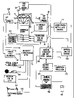
DETAILED DESCRIPTION OF THE PREFERRED EMBODIMENTS
The detailed preferred embodiments of the invention will now be described with
respect to the drawings. Like features of the drawings are indicated with the
same
reference numerals.
The system according to the present invention may be used to micro-inscribe
alpha/numeric characters on the girdle of diamonds 13. It is based on a pulse
laser 1, and
preferably a Q-switched laser diode pumped solid state laser, to provide
minimum
volume and installation requirements, and optimum compatibility with any
office
environment.
A preferred laser based inscribing system according to the present invention
thus
contains the following primary elements:
In a vibration isolated frame 140 with shock absorbers 141, at the positions
of support:
(1) Laser diode pumped laser 1 and programmable power supply 14, with a Beam
Expander 5.
(2) Optical assembly containing guiding 8 and focusing optics 10, miniature
CCD
cameras 28, 32 and illumination system.
(3) XYZ motion stages 50 (with Z elevator stage) including encoders 145,
limits
and DC brushless motors.
(4) Diamond holder 144 and accessories.
(5) Enclosure 142 with safety interlock 143 to prevent operation with open
cabinet and to prevent stray or scattered laser energy from posing a safety
hazard.
(6) Computer system 52 for control:
(a) PC (PentiumTM 100 Mhz), PCI bus, 1024 by 768 VGA monitor
CA 02621225 2008-02-29
26
(b) Frame grabber 56 (MatroxTM, videographic card).
(c) 3-axis motion controller card 60.
(d) Cables, Power Supplies.
(e) System operation software (WindowsTM)
(f) Application Software
Apparatus
As shown in Fig. 1, a Nd:YLF 2"d harmonic laser 1(QD321) is provided, which
emits a beam 2 having about 525 nm wavelength. A 1047 nm filter 3 is provided
to
attenuate any residual fundamental laser output energy, to produce a filtered
laser beam
4. The filtered beam is then expanded in a ten-times beam expander 5 to reduce
energy
density. In the path of the expanded beam 6, a 780 nm filter 7 is provided to
eliminate
energy from the diode pumps. A dichroic mirror 8 reflects the expanded,
filtered beam 9
toward a ten-times microscope objective 10. The microscope objective 10
focuses the
beam onto the workpiece 11, which is for example a girdle 12 of a cut diamond
13.
Fig. 2 shows the top illumination and imaging systems. An LED 20 or array of
LEDs having emission at about 650 nm projects through a collimating lens 21 to
produce
a collimated illumination beam 22. The collimated illumination beam 22
projects on a
beam splitter 23, which reflects the collimated illumination beam 22 toward a
reflecting
mirror 24. The reflected collimated illumination beam 25 passes through the
dichroic
mirror 8, parallel to the filtered beam 9, and through the microscope
objective 10 onto the
workpiece 11. The workpiece 11 reflects a portion of the illumination beam
back through
the microscope objective 10 and through the dichroic mirror 8, onto the
reflecting mirror
24, tracing an opposite path from the collimated illumination beam 25. A
portion of the
reflected illumination beam 27, however, passes through the beam splitter 23,
toward a
top CCD camera 28. Thus, the top CCD camera 28 views the workpiece 11 with the
650
CA 02621225 2008-02-29
27
nm illumination. When displayed on a 14 inch video monitor 159, the resulting
magnification of the image 29 is about 200 times.
The side illumination and imaging systems, shown in Fig. 3 is somewhat simpler
than the top illumination and imaging systems shown in Fig. 2. A set of spaced
650 nm
LEDs 30 produce illumination 31 at angles generally converging from the top
toward the
workpiece 11. A side CCD camera 32, views the workpiece 11 through a doublet
lens 33
and window 34, at right angles to the top CCD camera 28. The resulting image
35 of the
side CCD camera 32 on a 14 inch video monitor is also about 200 times
magnification.
Where the workpiece 11 is a cut diamond 13 having a girdle 12, the side image
35
includes the profile of the girdle 12'.
The bottom illumination system, shown in Fig. 4 includes a set of spaced
miniature arc lamps 40 below the workpiece 11, producing illumination along
paths 41
which are upwardly converging.
The stage positioning and control system is shown in Fig. 5. The workpiece is
mounted on a three axis stage 50, with encoder feedback in a workpiece mount
assembly
144. The drivers 51 for the three axis stage are provided within the laser
system enclosure
142, separate from the computer control 52. The computer control 52
communicates
through a positioning control system 53 (Galil), which is an ISA bus card. A
breakout
box 54 is provided within the laser system enclosure 142, which is connected
by a set of
cables 55 to the positioning control system 53.
As shown in Fig. 6 (prior art), a known system described in US Pat. 4,392,476
includes an X scanner 61 and a Z scanner 63, which steer the laser beam onto
the
diamond 13. This known system has limited repeatability. Further, the system
is
relatively large, and subject to vibrational influences.
Figs. 7A-7E show the diamond holder in top, side, side detail, mounted stone
holder, and unmounted stone holder, respectively. A slide 116 allows precise
positioning
with respect to a slot, within the cabinet. The slide 116 is positioned by a
set of hardened
steel balls and spring loaded balls which positions the holder 116 as it is
inserted into the
CA 02621225 2008-02-29
28
slot. A set of manual adjustments allow control over coarse 106 and fine 104
rotation,
with a lock/release chuck 107 provided. The workpiece 11 is set in a pot 108
mounted in
a chuck 109, with two round rods positioning the workpiece, held in place by a
finger
110.
As shown in Fig. 7D, a mounted workpiece holder allows a mounted workpiece
111 to be held precisely. A spring loaded trigger 112 is provided to allow
mounting and
unmounting of the mounted workpiece.
Mode of Operation
The system includes a static laser beam, e.g., a laser beam generation
apparatus
which does not move. The XYZ positioning system 50 moves the workpiece 11 and
generates the inscription with repeatability and resolution of about 1.0
microns. The beam
size at the focal point is greater than about 1 micron, so that the
positioning system 50
accuracy is not the limiting factor in the placement of the marking.
With the axis of symmetry of the workpiece 11, which is for example a diamond
13, horizontally disposed, the diamond girdle 12 is viewed horizontally
(profile mode)
and vertically (inscription mode) by two CCD cameras 28, 32. The vertical axis
also
corresponds to the axis of laser 1. A third camera may also be provided, for
example
having an optical path facing generally upward toward the laser. Of course, an
imaging
device facing the laser beam is provided in a manner to prevent damage during
operation.
Due to the focus of the laser 1, as well as filtering optics 8, 23, 34 there
is low risk of
damage to the CCDs 28, 32 due to laser energy. The user can choose to view one
or more
cameras. Where multiple images are present, they may be tiled at reduced size
on the
computer monitor screen 159. Using a mouse 161 as a pointing device, the
girdle 12 is
centered and focused by viewing the screen 159, using particularly a profile
view. The
diamond 13 can be manually rotated in its mounting 144 to bring the correct
part of the
girdle 12 to the center of a display window on the screen 159. The images are
provided
with a magnification of about 200 times, although other magnifications or
variable
magnifications are possible. Magnification is defined herein as the ratio of
the inscription
CA 02621225 2008-02-29
29
size as measured on screen 159 and that of the actual inscription size. In
general, a 14 or
15 inch diagonal video monitor is employed, with a resolution of 1024 by 768
pixels.
The user-entered portion of the content of the inscription is typed on a
keyboard
148 or entered by a bar-code reader 149 into the computer. Of course, the data
entry may
also be by voice through a microphone 150 for speech recognition, magnetic
strip
through reader 151, or through point-and-click operations using a computer
mouse 161.
The entered inscription and logo are shown on the video screen 159
superimposed on an
area corresponding to the girdle 12 of the diamond 13. Using the mouse 161 and
keyboard 160, the user can change all inscription characteristics in order to
fit it correctly
in the girdle 12. While the preferred user interface is a graphic user
interface with
pointing device (mouse 161), keyboard 160 and display screen 159, where the
user's
hands may be occupied, a voice-command recognition system may be used, e.g.,
through
microphone 150, with verification of all input information and commencement of
operational sequence by a specific sequence of actions by the user in fail-
safe manner, so
that, e.g., stray noises do not cause catastrophic interference.
In the horizontal camera 32 screen the user can measure the girdle 12 profile,
using a mouse input device 161 to mark the critical dimensions. This data is
then used to
keep the focal point of the laser output on the surface of the girdle 12 at
all times. The
profile data and girdle 12 outline may be automatically extracted from the
images, or a
manual entry step employed to outline the profile and/or girdle boundaries. In
general,
the inscription positioning on the girdle will be manually assisted, although
full
automation, especially for low value small stones, known as mellee, may be
employed.
When these procedures are complete a so-called G-code file is generated
containing all
inscription data. This file is transferred to the positioning stage controller
51 for
performance of the actual inscription.
The inscription code file may optionally be automatically generated and
authorized based on an algorithm to prevent unauthorized or fraudulent
inscriptions, as
depicted in Fig. 11. The authorization process according to one embodiment of
the
invention includes the steps of obtaining or retrieving an image of the
workpiece 171,
CA 02621225 2008-02-29
analyzing the image to determine characteristics of the workpiece 172,
transmission of
the characteristics in conjunction with data relating to the stone to an
authenticator,
through, for example, a telecommunications link 152, which may be at a
different
location, detemiining whether the characteristics and proposed marking are
unique 173,
which may be performed remotely, or locally, and if the characteristics and
marking are
not unique, proposing a change in the marking 174 and then reverifying the
modified
proposed marking with the authenticator. After a marking is approved, the
marking is
encrypted 175, and the encrypted code transmitted to the marking control 176.
Thus, only
if the authenticator approves a marking does the system commence marking.
The characteristics of the workpiece may be determined by eye 146, and may
also
be determined by a sensor 147 of appropriate type. For example, dimensions,
weight,
optical transmission characteristics, facet angles and the like may be
measured. During
the initial marking process, the characteristics are determined, and are
preferably stored
in conjunction with the marking information in a database 156. For example,
this
database may store images, compressed images or aspects of images derived from
the
CCD imagers 28, 32. Preferably, after the marking has occurred, the top CCD
imager 28
is used to capture an image of the marking, which is then stored. According to
one
embodiment of the invention, information stored in the database or marked on
the stone
may be encrypted using a secure encryption method by means of an encryption
processor
157, reducing the risk of fraud. Further, the marking may be, in part, self
authenticating
by including identification of characteristics of the marked workpiece. Of
course, the
encryption processor may be the same as the control system 155, and need not
be a
separate physical device.
The controller executes all 10 operations such as laser on/off, laser power
out of
range, limit switches, mouse, etc., as well as performing the motion itself.
Thus, the
control system may easily be upgraded as desired separately from the marking
system
hardware.
CA 02621225 2008-02-29
31
The operator can observe the diamond before, during and after the inscription
marking process. In case the inscription is not complete, the operator can
choose to repeat
all or selected parts of this inscription in a second or subsequent marking
operation.
Fig. 8 shows a flow diagram of the operation of the control system for the
laser
inscription process. A software module in the control system generates
interrupts which
sense laser system conditions, and may also initiate action automatically
based on those
conditions 121. The inputs to the laser system sensing module 121 include
emergency
stop 122, laser ready 123, mechanical limit reached 124, and door open 125. Of
course,
other conditions may be sensed and controlled by this sensing module 121.
A main interface screen 126 is provided allowing the operator to access and
control the main functionality of the laser inscription system. This interface
screen 126
initially controls laser warm up and positioning at a home position 127. After
a gemstone
is inserted into the laser inscription system, it is jogged into alignment 128
with reference
to the top and side views, displayed on the video monitor. Next, the
inscription is entered
or edited by an input device such as a keyboard 148 or bar code reader 149,
and the
inscription positioned with respect to the workpiece in the top view 129. If
the workpiece
has a rough surface, such as a brutted girdle of a diamond, the inscription
positioning is
verified in the side view 130. The host computer 52 sends commands to the
laser
inscription controller 60 defining the inscription pattern, by defining XYZ
positioning of
the workpiece 131 and a pattern of laser modulation 132, in order to define
the inscription
pattern, e.g., the font or logo structure. After all or a segment of the
inscription is made,
the inscription is verified to ensure complete inscription, and all or a
portion of the
inscription may be repeated as necessary 133. The inscription is then
complete, and a new
inscription process may be commenced 134.
In addition, a maintenance mode of operation is available, which allows
adjustment of system parameters 135, motion system diagnostics 136, and a
summary
report of inscription data 137.
CA 02621225 2008-02-29
32
INSCRIPTION SPECIFICATION
The length of inscription depends on size of characters and spacing. Below is
a
table representing appropriate dimensions:
HEIGHT WIDTH SPACING
(microns) (microns) (microns)
Large characters 80 60 30
Medium characters 60 45 25
Small characters 40 30 20
Ex. Small chars. 20 15 10
The total length of inscription = number of characters X (width + spacing) +
logo
length.
The system accommodates maximum single inscription lengths of approximately
2 mm. At an average of 80 microns per character (including spacing) this gives
25
characters which covers requirements for logo + 14 characters. Longer
inscriptions can
be implemented by consecutive inscriptions without dismounting diamond. In
this case
there is no limit on number of characters, except by the available surface
area. Each logo
+ 14 characters is accounted for as a single inscription process. Inscribing
more
characters would normally present no problem. It is noted that the characters
may be
alphanumeric, line-drawing, multi, lingual fonts, custom bitmaps, or other
pictorial
representations, and may be fully programmable.
The software of the control system also allows any number of inscribed
symbols.
It is also easy to rotate the stone and position a section of the inscription
so that it is or
seems to be continuous with the first one. Any symbol size may be produced,
within the
limits of the line width and surface to be inscribed. For example, with a red
beam, the
lower limit of symbol size is around 30 microns. With a green beam the lower
limit of
symbol size is about 15-20 microns.
The depth of inscription is less than about 10 microns.
CA 02621225 2008-02-29
33
The line width (green beam) is less than about 9 microns on a polished girdle
and
less than about 12 microns on a brutted girdle. The system employs a green
laser to
provide a finer inscription line width than is possible with a standard-type
red laser. Start
up time for the system is about 15 minutes, mostly accounted for by laser
stabilization
time, after which the instrument is fully operational, an advantage over other
laser types.
In a preferred marking method, the irradiated areas overlap, to provide an
appearance of
continuity of marking.
The laser output is provided as a Q-switched laser, which may be provided in a
range of about 1200 to 200 nm, with a frequency doubler or harmonic generator
as
necessary to provide an output wavelength of less than about 600 nm. A
preferred laser 1
is a Q-switched solid state neodynium laser, e.g., a laser diode pumped Nd:YLF
laser,
operating at 1.06 gm, with a frequency doubler to provide an output of 530 nm.
Operating according to the system heretofore described, net inscription times
(laser time) are estimated to be less than 20 seconds for polished girdles and
about less
than 35 seconds for brutted girdles.
On polished girdles, inscriptions are generally satisfactory after a first
pass.
Brutted girdles, on the other hand, may require multiple passes, depending on
surface
quality, to achieve a desired marking. For time efficiency, multiple runs are
executed
only on those characters requiring additional runs. These characters can be
marked with
the mouse. Of course, the reruns may be automatically performed based on a
predetermined criteria or based on optical feedback from the video cameras.
Mounting and dismounting the stone is performed using a modular holder 144
with a quick connect socket, and therefore may be accomplished in about 20-30
seconds.
The rest of the operations, e.g., locating optimal place for inscription,
painting, etc.,
depend on the manual skill of the operator, and may take about 30-40 seconds.
Consequently, 40 stones per hour throughput is possible using the apparatus
according to
the present invention.
CA 02621225 2008-02-29
34
DC brushless motors are employed in the translatable stage system 50. These
are
driven by a standard-type motor driver system. The X, Y stage employs linear
encoders
for feedback of stage position, while the Z stage employs a rotary encoder for
a helical
positioning mechanism.
FONT AND SYMBOL CAPABILITIES
An assortment of characters may be provided with each system, such as an ASCII
font set containing 26 letters and 10 numerals, business characters as
follows: (TM),
(SM), and a logo. These font sets are, e.g., available from Borland.
Additional fonts,
e.g., Japanese and/or Hebrew, and logos may, of course, be employed, e.g.,
added to the
system using removable magnetic media, smart cards, or by digital
telecommunication.
The font may also include custom or editable characters, allowing full freedom
to define
a raster bitmap represented by a character identification code. Thus, any
figure which can
be rendered in lines or a bitmap may be included as a marking.
Inscription data can be entered in three ways:
Manually-alphanumeric symbols entered from the keyboard 148 and logo selected
from
the logo library.
Semi-automatic - part of the alphanumeric symbols from bar-code 149 or from a
keyboard 148 and part of the symbols selected automatically by a serialization
counter.
Fully automatic - a complete inscription is generated by the device, after
inputting an
identification from bar code or similar system.
Using a graphic video overlay, the inscription position and dimensions can be
easily adjusted.
The system controller also provides over/under power protection. In case laser
power exceeds set limits the system will stop working and issue a warning,
thus ensuring
that no damage is caused to the diamond or a workpiece.
Vibration dampers 141 are provided at the base of the laser system frame 140
(Figure 14), by which the laser 1, the optical system and the stage 50 are
supported in
CA 02621225 2008-02-29
fixed relation. Thus, due to the compact size of the system and relatively
small
components, the frame 140 may have sufficient rigidity to provide isolation
from
vibrational effects. Operation is therefore possible in any normal office
environment at
normal room temperature, without extraordinary measures, such as strict
environmental
control, or active vibration damping.
The computer 52 is a"PC" type, and is generally provided as a separate
enclosure
from the laser inscribing system enclosure 142. Generally, two cables 55
connect the
computer controller 55 to the laser system enclosure 142, a motion controller
and laser
control cable and a frame grabber cable. The user may therefore position the
screen 159
and keyboard 160 with mouse 161 at the most convenient position.
INSCRIPTION OBSERVATION
The system includes two high resolution miniature CCD cameras with
illumination and filter systems for efficient viewing of entire inscription
process on a
video screen as follows:
The complete inscription with logo is projected on an image from a vertically
oriented camera 28 of the girdle 12 providing the user with the ability to
interactively
change length of inscription, height of characters remove and align the whole
inscription.
The girdle 12 area may be outlined by the user with a mouse 161 or
automatically
determined by image analysis in the computer system 52.
The operator can thus observe the inscription before marking; observe the
marking process itself, and then observe the result and decide if the
inscription is
complete or not. A protective enclosure 142 prevents scattered radiation from
reaching
operator eyes. Filters or the like may also be provided to prevent damage to
the video
cameras from reflected laser energy.
The operator is provided with complete control of positioning, and inscription
allowing approval of the inscription before laser operation. Cursors on the
screen help in
CA 02621225 2008-02-29
36
centering the inscription. The system also has a side camera 32 for girdle 12
profile
mapping and table viewing,
The operator marks as many points that are needed on the profile allowing the
system to then automatically adjust (Z-axis focal location) to conform to the
girdle profile
during marking. A manual override is also provided where the automated
inscription
depth control is not desired.
The side camera 32 allows precise determination of the position of the girdle
12
of the gemstone 11, so that the laser 1 may be focused onto the gemstone 11
surface with
high precision. In order to effectively ablate a small surface portion of the
gemstone 11,
without damaging deeper portions, or producing significant undesired thermal
stress
effects around the inscription, the laser 1 is provided with a very narrow
depth of field,
e.g., about 30 m. In addition, the small depth of field is required in order
to obtain
maximum power density from a relatively low power laser 1. Thus, by attempting
to
focus using a top view only, without a profile view, to achieve focus by
maximizing
contrast and edge sharpness, user discretion is required and accuracy is
limited. In
contrast, by providing a side view, the profile of the stone is aligned with a
predetermined
focal plane, assuring accuracy of about 7 m. In practice, at 200 times
magnification,
the 7 m corresponds to 2 pixels of the video imaging camera. Thus, after
determining
the exact focal plane of the laser 1 empirically, this plane may be provided
as a reference
in the control system, and the workpiece moved manually or automatically with
relative
ease to the desired locations). The reference may appear, for example, as a
line on a
computer monitor displaying a Z-axis video image of the workpiece. The
operator jogs
the Z-axis control until the profile of the workpiece 11 in the image is
tangent to the
reference line.
Vibration and or impact during, e.g., shipping, may alter the focal plane of
the
laser with respect to the workpiece mount 144. In this case, a simple "trial
and error" or
empirical study is conducted to redetermine the exact focal plane, which is
then used to
provide the correct reference in the control. This calibration study may be
conducted, for
example, on a relatively inexpensive diamond or other material test piece, in
which
CA 02621225 2008-02-29
37
successive ablations are conducted under differing conditions, e.g., differing
Z-axis
positions at successive positions in the X-Y plane. After the series of
ablations, the test
piece is examined to determine the optimal conditions of orientation, e.g.,
smallest spot
size. The conditions of the optimal orientation are then used to determine the
focal plane
and hence the calibrated reference plane.
The user has complete control over character sizing. Once the cursors are
placed
on the girdle (according to girdle dimensions) the computer will display a
first choice
which the user can change.
A motorized Z-axis is provided for focusing the laser onto the workpiece
surface.
This Z-axis is computer controlled, and enables the operator to focus onto the
girdle 12 of
the diamond 13 by means of the computer keyboard controls, with direct
position input to
computerized numeric control (CNC). The girdle profile is determined by
reference to an
orthogonal view to the girdle surface, and therefore the Z-axis may be
controlled for each
coordinate. A system may also be provided which uses hand operated micrometer
screws
for focusing, for example where long inscriptions on fancy shaped stones
necessitates the
use of segmented inscriptions.
The parameters of the inscription process, including laser power, Q-switch
frequency and inscription speed, may be controlled for optimization of the
laser-material
interaction when switching between substrates and differing surface qualities.
Thus, the
present invention allows the implementation of varying ablation sequences
based on the
desired inscription and the characteristics of the workpiece. Often, the
characteristics of
the workpiece are known and input into the control system, i.e., by a bar
code, magnetic
strip, manual keying, database retrieval, or other method. However, the system
according
to the present invention may also include a system for itself determining a
characteristic
or set of characteristics of the workpiece and implement an inscription
process based on
the input or determined characteristics and the desired resulting inscription.
Likewise,
where an inscription is preexisting, the system according to the present
invention may
analyze the existing inscription and produce a modified inscription. Thus,
where features
according to the present inscription method are desired, they may be
superimposed on or
CA 02621225 2008-02-29
38
added to existing inscriptions. Further, an old inscription may be analyzed
and stored
according to the present methods without any modifications thereto, e.g., for
security and
authentication purposes.
SOFTWARE
The computer controller preferably operates in a WindowsTM environment,
although WindowsTM 95 or NT, MacintoshTM, UNIXTM derivatives, X-terminal or
other
operating system which supports the various system components may be employed.
The
optical feedback system and preview of inscription functions advantageously
employ a
graphic user interface.
All machine features are generally controlled by the software, with the
exception
of laser pulse power and pulse frequency, which are set from power supply
panel. Of
course, the laser control system may be completely automated with a computer
control,
allowing software control over pulse power, Q-switch frequency, and
inscription speed.
User control and input for interaction with the software, which is preferably
a
graphic user interface system, is generally performed via mouse 161 and
keyboard 160.
Data entry of workpiece information may employ other input devices, such as a
microphone, optical or bar code scanner, gemstone characteristic sensor,
magnetic disk or
stripe, or other known input devices.
The software can generate various reports according to specifications and
formats
as desired, based on an individual inscription procedure or a number of
inscriptions. The
software may also be used to generate a certificate of authenticity with anti-
forgery and
anti- tamper features, with an image of the workpiece.
Images obtained through the CCD images can be stored, for example, on
magnetic disks or optical media, and may be stored locally or remotely. Such
storage may
be useful in order to identify and inventory workpieces, or to ensure system
operation.
CA 02621225 2008-02-29
39
The computer may also be provided with standard computer networking and
communications systems. For example, an Ethernet communication link, IEEE
802.3
may be used to communiicate over a local area network. Communications with a
central
database may occur over telephone lines using a standard analog modem, e.g.,
v.34,
ISDN, Frame Relay, the Internet (using TCP/IP), or through other types of
private
networks. Data is preferably encrypted, especially when in transit over
unsecure public
channels.
Logo and graphic editors are also provided for the creation of logos and
graphics.
A font editor is provided to edit character raster images of fonts. Because
the raster image
corresponding to each code is programmable or modifiable, complex symbols may
be
inscribed with the same ease as letters and numbers, once the symbol is
defined as a font
character. According to one aspect of the invention, a graphic pictorial image
is engraved
onto the stone, thereby making the stone an artwork. The pictorial image may
be identical
or different for each stone, and may also include encoded information. A logo
may differ
from a character by being larger, with potentially a higher dot density. Thus,
characters
are generally defined as raster bitmaps, while logos may be further optimized
or the laser
controlled to obtain a desired appearance.
STONE MOUNT
The mount includes a fixed base, held in fixed position with respect to the
frame
140, with a removable holder 118, as shown in Figs. 7A-7E. The holder 118 can
be easily
removed or taken out from the fixed base without changing the diamond's
orientation. A
holder 118 is selected based on the diamond size to be processed in the
machine, with
various holders available for differing sized stones. The diamond can be
easily placed in
or removed from the holder and can be externally adjusted to bring the correct
part of the
girdle to face the camera.
The diamond holder is based on a standard holder known in the diamond
industry.
The diamond center sits in a concave depression suited to the diamond size. A
spring
loaded metal strip 110 pushes against the table to hold the diamond securely
into the pot
CA 02621225 2008-02-29
108, while making sure that the table is parallel to the holder 118 axis. If
the girdle plane
is not parallel to the table or the girdle surface is not parallel to the
diamond axis of
symmetry, the holder provides two adjustments knobs 105, 117 to correct for
those cases
so that, when viewed through the video camera 28 on a video screen 159 the
girdle 12 is
horizontal and the entire relevant surface is in focus. In addition, there are
adjustments for
rough 106 and precise 104 rotation of the diamond 13 in the holder 118.
Rotation about
the center axis of the dianiond 13 is therefore achieved manually, although an
automated
or mechanized rotation is also possible. The rough adjustment 106 has 16
rotational steps,
while the fine adjustment 104 is continuous.
All of the above adjustments of the diamond in the holder 118 can be performed
outside of the inscribing apparatus and the diamond 13 can therefore be pre-
aligned
before insertion into the machine. The holder 118 is designed in a manner
enabling
access to all the adjustment knobs with one hand, while the holder 118 is
inserted into he
machine. Correction through visual on screen feedback 159 can be easily
achieved.
The user is provided with a range of controllable-intensity illumination aids.
The
laser axis, for example, is illuminated with a red LED 20, which is useful for
viewing
polished girdles 12 in the vertical (Z-axis) camera 28. In order to provide
high contrast
between the workpiece 11 profile and the background, three groups of LEDs 30
are
provided around the microscope objective 10, illuminating the workpiece 11
from three
sides. Each side- illumination group 30 may have, e.g., three LEDs. Further,
two
miniature arc lamps 40 are provided to illuminate the workpiece 11 from the
bottom. This
lower illumination is useful, e.g., for observing brutted girdles 12 of
diamonds 13 in the
vertical (Z-axis) camera 28.
The complete holder 118 is very easily inserted into the machine. In the
machine
there is a fixed base with a slot. The slide 116 of the holder 118 slides in
the slot, in the
manner of a credit card or cassette tape, and comes to a precise halt. Spring
based ball-
tipped plungers facilitate the sliding action and prevent the holder from
making any
movement when the machine is operating, by engaging countersunk recesses 103.
The
CA 02621225 2008-02-29
41
holder 118 can be taken out and inserted back again with the diamond 13 coming
to the
same place as before.
The general structure of the holder 118 is shown in Figs. 7A-7E. The operator
can
hold the unit with one hand, normally the left hand, and insert the holder
into the slot.
With the same hand the operator can make all the adjustments while monitoring
the video
screen and operating the mouse or keyboard with his right hand. The holder 18
position
in the slot is very well-defined and the holder can be taken out and
reinserted with the
diamond 13 and holder 118 regaining the same position. When taken out, the
holder 118
has an "out" position where it is still supported by the slide 116 and the
stone is 40 mm
out of the machine. In this position, the stone can be inked, inspected,
cleaned, etc.,
without need for the user to support the unit with one hand.
The stone 11 is positioned by the holder 118 and mount so that the center axis
is
horizontal and is perpendicular to the laser beam. The holder 118 is made of
steel. The
contact points are the concave cup 108 which supports the center of the
diamond, and a
strip 110 which presses on the table toward the cup 108 in a manner that
assures
parallelism of the table to the symmetry axis of the holder 118, and assures
correct
positioning with respect to the laser beam. In a preferred arrangement, three
sizes of
holders 118 are provided to cover a range of diamond 13 sizes. The holder 118
can
support any stone which has a center and a table. In addition, holders 118 may
also be
designed to accommodate special fancy shapes.
In general, it is desired to make the set-up and inscribing times
approximately
equal, so that the machine is always busy inscribing. Thus, further
improvements in set-
up time will not improve throughput. Therefore, a set of stone holders is
provided. The
user is provided with enough holders ready for inscribing, and that means the
machine is
inscribing almost continuously. The procedure is as follows:
Stones are prealigned on holders. The operator, on completing the inscription,
removes the holder with an inscribed stone and inserts a prepared holder with
a stone to
be inscribed. Minor adjustments may be required of the diamond or the holder,
which
CA 02621225 2008-02-29
42
may be accomplished under guidance of the video imaging system. In addition,
the
operator must also input or define the inscription. The inscription process is
then
commenced. During the inscription, the operator can remove the stone from the
previously used holder, allowing reuse. Generally, a large number of holders
will not be
required to ensure that the inscribing system is always busy, i.e., there is
always a holder
ready when the inscribing operation is complete. Where single operator
productivity is
maximum, a second operator may assist in mounting stones in holders and/or
defining the
inscription process.
Mounted stones are held by a holder 119 which has a design which depends on
the fact that some of the girdle 12 must be exposed for the inscription
process to take
place. Thus, the holder 119 is provided with three fine "claws" 120 which can
be opened
and closed by pressing a "trigger" 112. The claws 120 are spring loaded in the
closed
position. The claws 120 grasp around the girdle 12 (between prongs of the
setting) and
press the table against a flat surface 138 upon release of the trigger 112.
The flat surface
138 is perpendicular to the gemstone central axis. The holder 119 design thus
assures that
the gemstone 11 is centered and held firmly, and allows the stone to be
rotated to a
desired location for an inscription.
Since a mounted stone is held in an opposite manner from an unmounted stone,
the inscription direction is preferably reversed. This reversal is
accomplished, for
example, within the control software. In this case, the inscription may be
inverted, with
the inscription process commencing from the "beginning", or the inscription
made in
reverse order. In order to facilitate the following of the inscription process
by the human
operator, the inscription preferably proceeds from the "beginning", and the
reversal is
selected as a screen "button" of the graphic user interface system. In
addition, the
processed video image of the stone may also be selectively inverted, so that
the apparent
orientation of the stone in a processed image during mounted and unmounted
inscription
operations is the same.
The operator will always "OK" the process before laser operation. He will
either
see the complete inscription on the text screen, or on the video directly on
the girdle.
CA 02621225 2008-02-29
43
When the inscription is completed the operator can judge (even before
cleaning)
whether the inscription is successful. Even after cleaning, so long as the
stone remains
seated in the holder, will return to exactly the same position. The operator
can choose to
repeat the whole inscription or parts thereof any number of times he wishes
to.
Verification of the inscription is performed prior to removal of the diamond
from the
holder, so that the process may be repeated if necessary. The inscription is
clearly viable
on the video screen even before cleaning the ink/graphite from the stone. Even
with the
preferred 200 times magnification, an inscription will have to be extremely
long in order
not to be wholly visible on the screen.
AUTHENTICATION
Where a workpiece bears a marking, it may be desired to determine whether the
marking is authentic, for example according to the flow chart depicted in Fig.
12. The
workpiece is viewed under magnification to read markings present thereon 181.
The
authentication process provides at least two options. First, the markings may
be
encrypted, and are thus processed with a key 183, e.g., a public key. Where
the actual
characteristics of the stone form the encrypted message, the decrypted message
is
compared to the actual characteristics of the workpiece 184. Thus, the
authenticity may
be determined. Alternately, the markings may include a code which identifies
the
workpiece, allowing retrieval of information relating to the workpiece from a
database.
The database thus stores the characterizing information.
In a second embodiment, also shown in Fig. 12, the authentication process
involves a remote system. Therefore, the markings are transmitted to a central
system
182. The characteristics of the workpiece are read or extracted 185 and also
transmitted
to the central system 186. The central system then authenticates the marking
and the
characteristics 187, for example against a stored database of characteristics
of marked
workpieces. The authentication result is then transmitted to the remote site
189.
CA 02621225 2008-02-29
44
ENCRYPTION
A diamond 200, as shown in Fig. 13A, with further detail, enlarged in Fig.
13D, is
provided with a number of identification and security features. The diamond
200, for
example, is a color F stone weighing 0.78 Carats, grade VS2 with two
identified flaws
207. The diamond 200 has a set of markings inscribed on the girdle 201. The
markings
include an "LKT logo 202, formed as characters, a trademark registration
symbol 203, a
serial number in Arabic numerals 204, a one dimensional bar code 205, a two
dimensional code 206, a set of visible dimensional references 209, and single
ablation
spots 208, 210 having defined locations. For most purposes, the logo
identifies the series
of marking, while the serial number is used to identify the diamond 200. In
order to
encode further information, a visible bar code 205 allows, for example, binary
information to be encoded and retrieved from the diamond 200. The two
dimensional
code generally requires a machine for reading, and allows high density data
encoding.
The visible dimensional references 209 allow use of a reticle to measure
distances,
providing additional characteristics of the diamond 200 which may be used to
uniquely
define the diamond 200. The single ablation spots 208, 210 are less visible,
and may thus
require a key for searching. In other words, authentication of these spots may
require
transmission of their location, with confirmation by inspection of the diamond
200. The
marking 210, for example, has a defined physical relation to one or both flaws
207,
making copying very difficult.
Fig. l3B shows, in more detail, a typical two dimensional code, with simple
binary modulation. Thus, the presence 213 or absence 214 of an ablation at a
coordinate
211, 212 location defines the data pattern. On the other hand, Fig. 13C shows
a more
complex code. In this case, ablations are spaced discontinuously or partially
overlapping,
so that an outline or partial outline of each spot 223 may be identified. Due
to stochastic
processes, the actual placement of the center 224 of an ablation, or its
outline may vary.
However, the modulation pattern imposed may be greater in amplitude than the
noise, or
a differential encoding technique employed so that the noise is compensated.
Thus, an
array of spots 223 on generally coordinate 221, 222 positions, with the exact
positions
225 modulated according to a pattern 225. In this case, without knowledge of
the
CA 02621225 2008-02-29
modulation scheme, it would be difficult to read the code, thus making it
difficult to copy
the code. Further, to the extent that the noise amplitude is near the apparent
signal
amplitude, a copying system may require very high precision.
There has thus been shown and described novel receptacles and novel aspects of
laser workpiece marking systems and related databases, which fulfill all the
objects and
advantages sought therefor. Many changes, modifications, variations,
combinations,
subcombinations and other uses and applications of the subject invention will,
however,
become apparent to those skilled in the art after considering this
specification and the
accompanying drawings which disclose the preferred embodiments thereof. All
such
changes, modifications, variations and other uses and applications which do
not depart
from the spirit and scope of the invention are deemed to be covered by the
invention,
which is to be limited only by the claims which follow.