Sélection de la langue

Search

Sommaire du brevet 2621374 

Énoncé de désistement de responsabilité concernant l'information provenant de tiers

Une partie des informations de ce site Web a été fournie par des sources externes. Le gouvernement du Canada n'assume aucune responsabilité concernant la précision, l'actualité ou la fiabilité des informations fournies par les sources externes. Les utilisateurs qui désirent employer cette information devraient consulter directement la source des informations. Le contenu fourni par les sources externes n'est pas assujetti aux exigences sur les langues officielles, la protection des renseignements personnels et l'accessibilité.

Disponibilité de l'Abrégé et des Revendications

L'apparition de différences dans le texte et l'image des Revendications et de l'Abrégé dépend du moment auquel le document est publié. Les textes des Revendications et de l'Abrégé sont affichés :

  • lorsque la demande peut être examinée par le public;
  • lorsque le brevet est émis (délivrance).
(12) Brevet: (11) CA 2621374
(54) Titre français: AIGUILLE A TRICOTER FLEXIBLE
(54) Titre anglais: A FLEXIBLE KNITTING PIN
Statut: Accordé et délivré
Données bibliographiques
Abrégés

Abrégé français

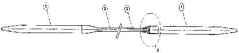
L'invention concerne une aiguille à tricoter flexible qui comprend deux tiges relativement rigides (1) aux extrémités pointues, lesdites tiges (1) étant reliées l'une à l'autre par un matériau de raccordement creux et flexible (2) comprenant un joint. Le joint disposé entre les tiges rigides (1) est caractérisé en ce qu'il comprend un matériau de raccordement creux et flexible.


Abrégé anglais


A flexible knitting pin consisting of two relatively stiff shanks (1) pointed
one end each, wherein said shanks (1) are connected with each other by the
other end with a flexible hollow connecting material (2) comprising a joint;
said joint between the stiff shanks (1) characterized in that it comprises a
flexible hollow connecting material .

Revendications

Note : Les revendications sont présentées dans la langue officielle dans laquelle elles ont été soumises.


WHAT IS CLAIMED IS:
1. A flexible knitting pin consisting of:
- two relatively stiff shanks pointed at
one end each having a ferrule which holds a
ball head screw; wherein each of said stiff
shanks are connected with each other by the
other end with a flexible hollow connecting
material comprising a joint;
- a brass adapter connecting said shank
and said flexible hollow connecting material
for smooth transition.
2. A flexible knitting pin as claimed in claim 1,
wherein said ferrule and said ball head screw
are made of brass.
3. A flexible knitting pin as claimed in claim 1,
wherein said flexible hollow connecting
material is a flexible hollow connecting tube.
4. A flexible knitting pin as claimed in claim 1,
wherein said joint consists of a metal sphere,
hemisphere or cone positioned inside the
hollow connecting material at a fixed position
up against the end of each of said stiff
shanks.
5. A flexible knitting pin as claimed in claim 1,
wherein each of said stiff shanks are made

from plastic, metal or wood.
6. A flexible knitting pin as claimed in claim 4,
wherein said metal sphere, hemisphere or
cone inserted in the hollow connecting
material rests against the flat end of each of
said stiff shanks.
7. A flexible knitting pin as claimed in claim 1,
wherein each of said stiff shanks is made of
rose wood and the hollow flexible connecting
material is made of polyurethane.
8. A process for manufacturing the flexible
knitting pin as claimed in claim 1, said
process comprising:
- finishing one end of the shank to a
diameter suited to the inner diameter of the
brass adaptor;
- inserting the head of the ball headed
screw into the hollow flexible, connecting
tube;
- attaching the threaded portion of the
ferrule to the adaptor, either directly or using
the ferrule depending upon the size of
knitting pin, using an adhesive; fastening the
adaptor carrying the ball headed screw and
said ferrule fixed to the hollow connecting
tube with the help of adhesive.
11

Description

Note : Les descriptions sont présentées dans la langue officielle dans laquelle elles ont été soumises.


CA 02621374 2008-03-04
WO 2007/049300 PCT/IN2006/000417
A FLEXIBLE KNITTING PIN.
FIELD OF THE INVENTION
The present invention relates to flexible knitting
pin, specifically circular knitting pin made from
any material. Accordingly, a method to realize
this invention is also provided.
BACKGROUND OF THE INVENTION
Conventional knitting pins are known to have
metal shanks comprising of a nylon
monofilament. The step formed at the junction,
usually prepared from nylon monofilament is not
smooth and therefore, the step catches the wool.
This results in obstructed functioning of the
knitting pin.
British patent GB876144 describes circular
knitting pins of two relatively stiff metal end
parts joined by a flexible connection made from
a polymer plastics material. The flexible
1

CA 02621374 2008-03-04
WO 2007/049300 PCT/IN2006/000417
connecting tube is joined to, the end parts by
making axial bores in the undrawn end portions
of the flexible connection made from a length of
moulded or extruded plastic material, inserting
the surface roughened spigots into the axial
bores of, the flexible connection while supplying
sufficient heat to the junctions to cause the end
parts and the connections to become fixed
together and further elongating and reducing in
cross-section the intermediate portion of the
flexible connection until further elongation is
strongly resisted.
SUMMARY OF THE INVENTION
The present invention relates to a flexible
knitting pin consisting of two relatively stiff
shanks (1) pointed at one end each, wherein said
shanks are connected with each other by the
other end with a flexible hollow connecting tube
(2) comprising a joint; said joint between the stiff
shanks (1) and the flexible hollow connecting
tube (2) consisting of a metal sphere,
2

CA 02621374 2010-02-10
hemisphere or cone positioned inside the hollow
connecting tube (2) at a fixed position up against
the end of the stiff shank.
In accordance with another aspect, there is
provided a flexible knitting pin consisting of:
- two relatively stiff shanks pointed at one
end each having a ferrule which holds a ball head
screw; wherein each of said stiff shanks are
connected with each other by the other end with
a flexible hollow connecting material comprising
a joint;
a brass adapter connecting said shank and
said flexible hollow connecting material for
smooth transition.
In accordance with a further aspect, there is
provided a process for manufacturing the flexible
knitting pin as claimed in claim 1, said process
comprising:
finishing one end of the shank to a
diameter suited to the inner diameter of the brass
adaptor;
inserting the head of the ball headed screw
into the hollow flexible, connecting tube;
3

CA 02621374 2010-02-10
attaching the threaded portion of the
ferrule to the adaptor, either directly or using the
ferrule depending upon the size of knitting pin,
using an adhesive; fastening the adaptor carrying
the ball headed screw and said ferrule fixed to
the hollow connecting tube with the help of
adhesive.
The invention also provides a method for the
manufacture of the flexible knitting pin.
DETAILED DESCRIPTION OF THE INVENTION
The present invention relates to a flexible knitting
pin, specifically, circular knitting pin made from
any material which enables smoother movement
of stitches compared to the prior art and is easier
to use. Also, the method of realizing this
invention is relatively simple while maintaining
the same functionality.
The knitting needle consists of two stiff shanks
which are pointed at one end and suitably
machined for attachment at the other. These
shanks are then connected to each other using a
flexible tube.
3a

CA 02621374 2008-03-04
WO 2007/049300 PCT/IN2006/000417
Thus the product consists of two stiff shanks,
suitably pointed at one end each for knitting and
connected from the other end using a flexible
hollow tube. The joint between the stiff shanks
and the flexible hollow connecting tube consists
of a metal sphere, hemisphere or cone
positioned inside the hollow connecting tube at a
fixed position up against the end of the stiff
shank. The joint between the stiff shanks and
the hollow flexible connecting tube is extremely
smooth to enable the individual stitches to slide
over the connection without impairment and
without the yarn snagging at the connection.
Another aspect of the invention is the method to
realize this invention. The two stiff shanks of the
knitting needle are made from plastic, metal or
wood. The joint between the stiff shanks and the
flexible hollow connecting tube is made by
insertion of a metal sphere, hemisphere or cone
into the hollow connecting material in such a
4

CA 02621374 2008-03-04
WO 2007/049300 PCT/IN2006/000417
way that the ball rests against the flat end of the
stiff shank.
In a preferred embodiment,. the shank is made of
rose wood whereas the hollow flexible connecting
tube is made of polyurethane. At one end of the
shank is a ferrule made of brass which holds a
ball head screw made of brass. To enable a
smooth transition between the shank and the
hollow flexible connecting material, an adaptor
made of brass has been put at the joint.
In another embodiment of the invention, a
method for the manufacture of the flexible
knitting pin is provided. The shanks are
manufactured by conventional manufacturing
processes. The attachment to the flexible
material is the substance of the invention. The
flexible material used is in the form of a
polyurethane tube. This polyurethane tube is
connected to the rigid shanks using a brass
5

CA 02621374 2008-03-04
WO 2007/049300 PCT/IN2006/000417
adaptor, a ball headed screw and a threaded
ferrule.
The joint itself is made up of brass parts which
are attached to the wooden shank and to the
polyurethane flexible tube. The brass ferrule and
adaptor are manufactured by conventional
turning processes using automatic lathes. They
are fashioned from brass rod. These parts are
then lacquered to prevent tarnishing. The
tolerances are such that they meet the
requirements of the product and the joint.
The ball headed screw is manufactured, out of
brass rod, in a two stage operation. The first
stage is a standard turning operation carried out
on automatic lathes. The second stage is a
stamping operation which is carried out on a
special purpose machine built and designed by
the applicant. After the second operation, the
screw is lacquered to prevent tarnishing.
6

CA 02621374 2008-03-04
WO 2007/049300 PCT/IN2006/000417
The rigid shanks are made with the back end
(the end that is not pointed) finished to a
diameter suited to the inner diameter of the
brass adaptor. The head of the ball headed
screw is inserted into the polyurethane tube.
The threaded portion of the ball headed screw is
attached to the adaptor either directly, or using
the ferrule (depending upon the size of knitting
pin).
Adhesive is applied to the threaded portion to
ensure that it locks tight. The adaptor carrying
the ball headed screw, ferrule and attached to
the polyurethane tube is then fastened to the
shank with the use of an adhesive.
The above method results in an extremely
smooth joint between the rigid shank and the
flexible tube.
DETAILED DESCRIPTION OF THE
ACCOMPANYING DRAWINGS
7

CA 02621374 2008-03-04
WO 2007/049300 PCT/IN2006/000417
Fig. 1 illustrates a perspective schematic view of
the present invention. The two relatively stiff
ends of the pin are denoted by 1 whereas the
hollow flexible connecting tube between the two
pins is denoted by 2. The shank is made from
rosewood whereas the hollow flexible connecting
tube is made from polyurethane.
Fig. 2 illustrates one of the ends of the pin or
shank which is pointed at one end and the other
end forms a joint with the hollow flexible
connecting tube.
Fig. 3 illustrates the junction between the shank
and the hollow flexible connecting tube where
the assembly of adaptor (3), ferrule (4) and the
ball screw head (5) is shown in detail.
Fig. 4 illustrates the adaptor (3) which provides
a smooth transition between . the hollow flexible
connecting material and the shank. The adaptor
is made from brass.
8

CA 02621374 2008-03-04
WO 2007/049300 PCT/IN2006/000417
Fig. 5 depicts the ferrule (4) which holds the ball
head screw in place. The ferrule is made from
brass.
Fig. 6 illustrates the ball.head screw (5). The
screw is made of brass.
Various modifications and alterations of this
invention will become apparent to those skilled
in the art without departing from the scope and
spirit of this invention and it should be
understood that this invention is not unduly
limited to the illustrative embodiment set forth
herein.
9

Dessin représentatif
Une figure unique qui représente un dessin illustrant l'invention.
États administratifs

2024-08-01 : Dans le cadre de la transition vers les Brevets de nouvelle génération (BNG), la base de données sur les brevets canadiens (BDBC) contient désormais un Historique d'événement plus détaillé, qui reproduit le Journal des événements de notre nouvelle solution interne.

Veuillez noter que les événements débutant par « Inactive : » se réfèrent à des événements qui ne sont plus utilisés dans notre nouvelle solution interne.

Pour une meilleure compréhension de l'état de la demande ou brevet qui figure sur cette page, la rubrique Mise en garde , et les descriptions de Brevet , Historique d'événement , Taxes périodiques et Historique des paiements devraient être consultées.

Historique d'événement

Description Date
Représentant commun nommé 2019-10-30
Accordé par délivrance 2010-09-28
Inactive : Page couverture publiée 2010-09-27
Inactive : Taxe finale reçue 2010-07-20
Préoctroi 2010-07-20
Un avis d'acceptation est envoyé 2010-05-21
Lettre envoyée 2010-05-21
Un avis d'acceptation est envoyé 2010-05-21
Inactive : Approuvée aux fins d'acceptation (AFA) 2010-05-13
Modification reçue - modification volontaire 2010-02-10
Inactive : Dem. de l'examinateur par.30(2) Règles 2009-11-17
Inactive : IPRP reçu 2008-07-16
Lettre envoyée 2008-06-25
Inactive : Page couverture publiée 2008-05-30
Inactive : Inventeur supprimé 2008-05-27
Inactive : Notice - Entrée phase nat. - Pas de RE 2008-05-27
Toutes les exigences pour l'examen - jugée conforme 2008-03-28
Exigences pour une requête d'examen - jugée conforme 2008-03-28
Requête d'examen reçue 2008-03-28
Inactive : CIB en 1re position 2008-03-21
Demande reçue - PCT 2008-03-20
Exigences pour l'entrée dans la phase nationale - jugée conforme 2008-03-04
Demande publiée (accessible au public) 2007-05-03

Historique d'abandonnement

Il n'y a pas d'historique d'abandonnement

Taxes périodiques

Le dernier paiement a été reçu le 2009-10-05

Avis : Si le paiement en totalité n'a pas été reçu au plus tard à la date indiquée, une taxe supplémentaire peut être imposée, soit une des taxes suivantes :

  • taxe de rétablissement ;
  • taxe pour paiement en souffrance ; ou
  • taxe additionnelle pour le renversement d'une péremption réputée.

Les taxes sur les brevets sont ajustées au 1er janvier de chaque année. Les montants ci-dessus sont les montants actuels s'ils sont reçus au plus tard le 31 décembre de l'année en cours.
Veuillez vous référer à la page web des taxes sur les brevets de l'OPIC pour voir tous les montants actuels des taxes.

Titulaires au dossier

Les titulaires actuels et antérieures au dossier sont affichés en ordre alphabétique.

Titulaires actuels au dossier
T.A. DEVAGNANAM
Titulaires antérieures au dossier
S.O.
Les propriétaires antérieurs qui ne figurent pas dans la liste des « Propriétaires au dossier » apparaîtront dans d'autres documents au dossier.
Documents

Pour visionner les fichiers sélectionnés, entrer le code reCAPTCHA :


Pour visualiser une image, cliquer sur un lien dans la colonne description du document (Temporairement non-disponible). Pour télécharger l'image (les images), cliquer l'une ou plusieurs cases à cocher dans la première colonne et ensuite cliquer sur le bouton "Télécharger sélection en format PDF (archive Zip)" ou le bouton "Télécharger sélection (en un fichier PDF fusionné)".

Liste des documents de brevet publiés et non publiés sur la BDBC .

Si vous avez des difficultés à accéder au contenu, veuillez communiquer avec le Centre de services à la clientèle au 1-866-997-1936, ou envoyer un courriel au Centre de service à la clientèle de l'OPIC.

({010=Tous les documents, 020=Au moment du dépôt, 030=Au moment de la mise à la disponibilité du public, 040=À la délivrance, 050=Examen, 060=Correspondance reçue, 070=Divers, 080=Correspondance envoyée, 090=Paiement})


Description du
Document 
Date
(aaaa-mm-jj) 
Nombre de pages   Taille de l'image (Ko) 
Description 2008-03-03 9 212
Revendications 2008-03-03 2 58
Dessins 2008-03-03 4 26
Abrégé 2008-03-03 2 58
Dessin représentatif 2008-05-27 1 4
Revendications 2008-03-04 2 90
Description 2010-02-09 10 239
Revendications 2010-02-09 2 53
Accusé de réception de la requête d'examen 2008-06-24 1 177
Avis d'entree dans la phase nationale 2008-05-26 1 195
Avis du commissaire - Demande jugée acceptable 2010-05-20 1 167
Paiement de taxe périodique 2023-10-15 1 26
PCT 2008-03-03 8 235
PCT 2008-03-04 8 297
Taxes 2009-10-04 1 72
Correspondance 2010-07-19 1 65
Taxes 2010-10-11 1 71
Taxes 2011-10-11 1 63
Paiement de taxe périodique 2017-10-22 1 25
Paiement de taxe périodique 2022-07-12 1 26