Note : Les descriptions sont présentées dans la langue officielle dans laquelle elles ont été soumises.
CA 02623303 2008-03-20
WO 2007/033486 PCT/CA2006/001563
FOAM FINISHING DEVICE
The present invention relates in general to apparatus for effecting the
finishing of
elongated profiled workpieces, and more particularly to devices especially
adapted for
the finishing of decorative moldings.
BACKGROUND TO THE INVENTION
In the construction and renovation of buildings, whether residential or
commercial, it is common to complete each room with the application of
elongated strips
of molding along specific portions of a wall. Baseboard is applied to the
bottom edge of
each wall where it meets the floor. Shoe molding may be applied to the bottom
edge of
baseboard where it meets a solid floor (hardwood, vinyl, concrete, etc.).
Crown molding
may be applied to the upper edge of a wall where it meets the ceiling. Casing
may be
applied around door and/or window openings. Chair rail may be applied to a
wall part
way up the vertical extent of a wall, running parallel to the floor. Bead
board allows for
panelling such as wainscoting to be installed underneath the bottom half
thereof to finish
a partial wall. Other types of decorative molding may be applied to a wall
surface to
define decorative areas.
Elongated strips of molding have much in common, in particular a rear surface,
that is generally planar and will usually abut against a wall, floor or
ceiling surface.
Crown molding, which is generally angled relative to a wall and a ceiling will
have a rear
surface that includes angled corner edges that together generally form a 90
angle
therebetween for abutment against both the ceiling and the adjacent wall. Each
strip of
molding will have upper and lower edge surfaces extending outwardly from the
upper
and lower edges of the rear surface, which edge surfaces will generally be
contoured so
as to curve into or mate with a front surface that is profiled to have a
specific defined
contour in transverse cross-section of the molding strip. The contour can be
as simple
as a planar surface as in door or window casing or a very complex arrangement
of
concave and/or convex curved sections and/or straight sections. It is
interesting to note
that while there are many manufacturers of moldings, the WMMPA (Wood Mould,
Milling
Profile Association) has defined the actual molding profiles so that a
standard thereof
exists. Thus a 3%" Colonial molding will have the same profile no matter which
manufacturer provides the molding.
Moldings can be made from different materials, both natural and synthetic.
Wood
moldings can be formed from solid woods such as oak, pine or maple and will
not have
1
CA 02623303 2008-03-20
WO 2007/033486 PCT/CA2006/001563
any joints therein. Moldings can also be made from shorter lengths of
material, and thus
include several joints over the length thereof. Finger-jointed pine moldings
for example
fall into that category. Such moldings generally are not pre-finished at the
factory. It is
up to the contractor or the homeowner to finish the molding with paint, stain
and/or a
varnish or urethane coating. Growing in popularity are factory-primed
moldings, rapidly
becoming the largest selling group of moldings.
Moldings made from medium density fiberboard (MDF) can be unfinished or
provided with a coat of a primer paint. Generally MDF moldings will be painted
rather
than stained as they do not have any grain and would not be attractive with a
stained
finish. MDF moldings can also be prefinished with a paper or vinyl layer so
that further
finishing is not required.
There is also a trend to plastic extruded moldings that have the finish
incorporated therein, although such moldings tend to be provided with a white
colour
finish, with either a gloss or a semi-gloss appearance.
Moldings formed from wood and MDF have in common the feature that additional
finishing is required in order to obtain molding that is both attractive and
long-lasting.
With such moldings it is usually necessary to lightly sand the material so as
to accept the
finish material and to then apply the finish using a bristle brush or a foam
pad. This is a
labour intensive task as it is difficult to both apply a uniform coating of
the finish
material and to ensure that the material is applied to all areas of the
surface to be
finished. With moldings having a complex contour it is difficult to apply the
coatings into
all nooks and crannies of the contour. Furthermore, the finishing process can
involve
several applications of finish, whether stain, paint and/or protective
urethane or varnish,
with a light sanding between coats, thereby increasing the time required to
finish the
moldings. Usually the finishing is effected prior to attachment of the molding
to the wall,
floor or ceiling and thus there can be many lengths of molding lying around a
work area
in various stages of finishing, making it awkward for workers to effectively
work in the
area.
Even though the molding may have paint or stain applied thereto prior to
installation it is usual to apply a final finish coat once the molding has
been installed in
its final location. It is difficult to apply the final finish coat without
taking extra
precautions to avoid inadvertent application of finish to surrounding
material, such as a
wall, carpet or floor.
2
CA 02623303 2008-03-20
WO 2007/033486 PCT/CA2006/001563
Many other construction materials require finishing in one form or another,
including planking used for decks or fences or logs used in log home
construction. Other
types of profiled or contoured items requiring finishing include, but are not
limited to,
railings, banisters, hand holds and rail caps.
There is therefore a profound need for any device or process that will speed
up
the finishing of moldings and other profiled or contoured building materials
and that will
improve the end result, insofar as a uniform and attractive finish is
concerned.
SUMMARY OF THE INVENTION
The present invention serves the purpose of improving the finishing of
elongated
workpieces, of any length, making the finishing task simpler and more
effective that
previously. In short, the present invention provides a device for use in the
finishing of
elongated workpieces which comprises a gripping portion and a finishing
portion, the
finishing portion being an open-cell foam material that has a transversely
contoured
working surface, the working surface having a transverse contour that is
complementary
to the transverse contour of the elongated workpiece to be finished. The
finishing device
of the present invention can be dipped into a liquid finish material, such as
paint, stain,
varnish, shellac or urethane, placed on the elongated workpiece at one end
thereof with
the contoured surface of the finishing portion mating with the contoured
surface of the
workpiece, and then slid along the workpiece so as to transfer the finish
material from
the device onto the surface of the workpiece. It only takes a single pass of
the device
along the workpiece to apply a smooth uniform coating of finish material to
the
workpiece, the length of coating applied only depending on the amount of
coating
originally held by the working surface of the device. If there is insufficient
finish material
carried initially by the device, it is again dipped into a reservoir of the
finish material and
then applied to the unfinished portion of the workpiece to complete the
application
process. It takes much less time to apply the finish material using the device
of the
present invention than to apply the finish using a brush. Furthermore there
are no brush
strokes associated with the present device and the end result is a more
uniform finish
than can be obtained with a brush application.
The device of the present invention is inexpensive to manufacture and thus is
a
disposable item, to be thrown away once a particular job is complete. A
contractor or
homeowner could obtain a complete set of finishing devices to encompass all of
the
different workpiece profiles that he works with, using them to apply paint,
stain,
3
CA 02623303 2010-05-11
urethane or varnish to the workpieces. If the workpiece requires cleaning
using a liquid
cleaner the device of the present invention can be used to apply the cleaner
and it could
also be used to wipe any excess cleaner from the surface of the workpiece, as
required.
A new, clean or unused device of the present invention could also be used to
remove
dust or debris from a workpiece prior to the finishing thereof.
The device of the present invention could also be manufactured with the
profiled
foam working surface thereof having been impregnated or overlaid with an
abrasive
substance such that the device could be used to effect a "sanding" or abrading
operation
on the workpiece before initial coating and/or between coatings.
Further details respecting the present invention will be realized from the
description to
be provided hereinbelow in association with the attached drawings.
BRIEF DESCRIPTION OF THE DRAWINGS
Each of Figures 1A, 2A, 3A, 4A, 5A, 6A, 7A and 8A shows an end view of the
molding with which the particular finishing device is utilized.
Each of Figures 1B, 2B, 3B, 4B, 5B, 6B, 7B and 8B shows a perspective view of
the particular finishing device used with the particular molding profile.
Each of Figures 1C, 2C, 3C, 4C, 5C, 6C, 7C and 8C shows in transverse cross-
section a molding having a specific profile abutting a surface and a finishing
device of the
present invention in contact therewith.
Figure 9 shows a finishing device that could be used with a workpiece of
rectangular cross-section, as might be used for deck or fence construction.
Figure 10 shows a finishing device that could be used to apply finish material
to
an elongated log as used in a log home construction.
Figure 11 shows a representative finishing device having a particular form of
gripping element secured thereto.
Figure 12 shows a finishing device adapted to function as a sanding block.
DESCRIPTION OF THE PREFERRED EMBODIMENTS
Each of "A" Figures 1A through 8A shows an end view of a particular molding
profile,
the profile pattern number as established by the WMMPA being shown thereon.
Figures IA
shows a casing 12; Figure 2A shows another casing 14; Figure 3A shows yet
another casing
16; Figure 4A shows a baseboard 18; Figure 5A shows another baseboard 20;
Figure 6A
shows a chair rail 22; Figure 7A shows a bean board 24; and Figure 8A shows
4
UNNOWNWOMM~
CA 02623303 2010-05-11
a crown molding 26. It is understood that these moldings are elongated, coming
in
lengths of 7, 8, 12, or 16 feet and that they can come in different widths
albeit with the
same general profile. Furthermore it is to be understood that the profiled
moldings
shown in these figures are representative of the available molding profiles
and that other
profiles are also available. Simple cove and quarter-round moldings, for
example, have
not been illustrated herein.
All of the illustrated moldings, as well as those not shown herein, have in
common the feature of a specifically defined profile or contour that exists
transversely
across the piece, herein referenced as a workpiece. Generally speaking, each
workpiece
has a rearmost face 12a, 14a, 16a... 26a respectively. The rearmost face can
be
relatively flat, as with the workpieces 12, 14, 18, 20 and 22, perhaps having
a
longitudinally extending relief groove 28 therein; the face can be somewhat
concave, as
with the workpiece 16; the face can be stepped, as with the workpiece 24; or
the face
can have bevelled edge sections 30, 32 as with the workpiece 26. Each
workpiece has
what can be termed as upper and lower edge surfaces 12b, 12c; 14b, 14c..26b,
26c
respectively which extend outwardly of the rear surface. Finally, each
workpiece has a
transversely extending profiled front surface 12d...26d respectively which can
be as
simple as the surface 18d shown in Figure 4A to the more complex profiles 22d
and 26d
of Figures 6A and 8A respectively. Each profile presents its own problems in
the
application of finishing material thereto, especially the complex profiles
made up of
combinations of convex, concave and/or straight portions. The more complex the
profile
the more difficult it is to apply the finishing material in a uniform manner
so that there is
no unwanted accumulation of material where, for example, a curved portion
meets a
straight portion, or so that there are no portions of the profile, as for
example where a
curved portion meets a straight portion, where there is insufficient material
applied to
the workpiece surface.
Each of "B" Figures 1B through 8B illustrate a finishing device of the present
invention which is especially adapted to apply a finish or cleansing liquid to
an elongated
workpiece of the associated "A" figure. Thus, in Figure 1B there is shown a
device 40a
which has a finishing portion 42a and a gripping portion 44. The finishing
portion 42a is
preferably formed from an open cell foam material such as commonly available
polyester
foam, urethane foam, et cetera. Such a foam is capable of being worked and is
also
capable of absorbing liquid material, such as paint, stain, varnish, shellac,
urethane, et
cetera and of releasing the material with moderate pressure applied thereto.
CA 02623303 2010-05-11
The finishing portion 42a has a working surface 46a that is transversely
contoured to conform or to be complementary to the profiled front surface 12d
of the
workpiece 12 as well as to the upper and lower edge surfaces 12b, 12c of the
workpiece.
Preferably, the upper and lower edges of the finishing portion are bevelled or
chamfered
as shown at 47a, establishing a "take away" surface or edge that angles
outwardly from
each end of the working surface 46a to the adjacent side wall of the finishing
portion.
Additionally, the edge defined by the juncture of each angled surface 47a with
the
working surface 46a is short of the full depth or height of the molding 12
shown in Figure
IA. Thus, if the finishing device of Figure 16 were laid on the workpiece of
Figure 1A
with no pressure applied thereto the edge defined by the juncture of each
angled surface
47a with the working surface 46 would be positioned above the rear surface 12a
of the
molding 12. In use, however, as seen in Figure 1C, a modest amount of pressure
applied
inwardly to cause liquid to ooze from the finishing portion 42a will bring the
edges as
defined closer to the wall 48 to effect the transfer of finish material to the
full extent of
the edge surfaces 12b and 12c. Furthermore, by minimizing the possible contact
between the finishing portion and the adjacent wall or substrate the
possibility of finish
material being inadvertently applied to the wall or substrate is minimized.
The gripping portion 44 may just simply be a designated portion of the
applicator
device 40a if the entire device is made of open cell foam. Alternatively, the
gripping
portion 44 may be a separate section of a more dense material, such as a
closed cell
foam material, that is adhered or fused to the finishing portion 42a. The
gripping portion
could even be a block of a solid material such as wood that is adhered to the
finishing
portion. It could even be a commercially available handle or grip. When a
gripping
portion that is more dense than the finishing portion is used the finishing
portion is able
to perform its function more effectively. A fairly rigid gripping portion
could have a swivel
with a threaded socket secured thereto for reception of the threaded end of an
extension
pole to enable the device to be used at a distance from the person applying
the finish
material. This would be most useful when attempting to finish crown molding,
fencing or
decking.
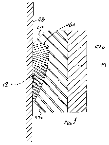
Figure 1C shows the finishing device 40a of the present invention applied to
an
elongated workpiece 12 of Figure 1A, with the workpiece being affixed to a
supporting
surface 48 such as a wall. The close conformance of the working surface 46a of
the
device 40a relative to the profiled surfaces 12b, 12c and 12d of the workpiece
is clearly
seen in Figure 1C, there being little or no space between the mating or
complementary
6
CA 02623303 2010-05-11
surfaces. In operation the finishing portion 42a is dipped into the finishing
liquid, e.g.
stain, so that a volume of the finishing material is absorbed by the open cell
finishing
portion 42a. The device is then brought to the workpiece with the working
surface 46a
being moved into contact in conforming fashion to the profiled edge and front
surfaces of
the workpiece. With moderate pressure applied to the device via the gripping
portion the
device is slid or wiped along the length of the workpiece whereby the
finishing material
is transferred from the finishing portion to the profiled surfaces of the
workpiece. The
end result is a smooth even coating applied to the profiled surfaces. If the
liquid material
runs out before the full length of the workpiece has been coated, the
finishing portion
42a of the device 40a is again dipped into the reservoir of finishing material
and then the
remaining unfinished section of the workpiece can be coated.
Because of the angled "take away" surfaces 47a there will be no contact
between
the finishing portion and the wall 48, meaning that no liquid finishing
material will be
inadvertently applied to the wall.
The only difference among the finishing devices 40b through 40h of "B" Figures
2B through 8B respectively lies in the particular profile of the working
surface 46b
through 46h of each finishing portion 42b through 42h. In each case the
profile of the
working surface is complementary to the profile of the respective workpiece
with which it
is adapted to be used. Each such finishing device will have the angled "take
away"
surfaces 47b...47h respectively associated therewith. It is noted that in the
embodiment
of Figure 8B the angled surface 47h need not be markedly angled relative to
the
adjacent side wall of the finishing portion since the device 40h will be used
at an angle
to the wall and ceiling surfaces to which the crown molding is affixed. The
gripping
portion 44 will be the same as the gripping portion described for the
exemplary
embodiment of Figure 1B.
Figure 9 shows a finishing device 50 that has a rectangular finishing portion
52,
angled "take away" surfaces 57, a gripping portion 54 and a simple rectangular
working
surface 56 that is especially adapted to apply liquid material to an elongated
workpiece
that has a flat front surface, such as a length of lumber that might be used
as a deck
board or a fence board. The width of the working surface 56 would be
complementary to
the width of the lumber workpiece.
Figure 10 shows a finishing device 60 that has a generally rectangular
finishing
portion 62, angled "take away" surfaces 67, a gripping portion 64, and a
generally
arcuate working surface 66. Arcuate working surfaces of varying diameters
could be
7
CA 02623303 2008-03-20
WO 2007/033486 PCT/CA2006/001563
provided so that the device 60 could be used with any type of transversely
curved or
profiled workpiece of essentially any diameter, ranging from small diameter
lengths of
dowling through to large diameter logs as might be used in log home
construction.
Figure 11 shows a finishing device in which the gripping portion 70 is
provided
with a groove 72 extending into the body thereof from the outermost surface
74. The
groove 72 provides a rest for a finger of the person using the device, giving
the person
greater control of the movement of the device and also permitting greater
control of the
application of inward pressure and hence the transfer of liquid finishing
material to the
workpiece. The gripping portion 70 can be used with any of the finishing
devices
illustrated in the drawings.
The device of the present invention is not limited to the application of
liquid
finishing material to a workpiece. Other types of liquid material can be
applied to the
workpiece and/or wiped therefrom. Cleansing liquids or paint removers are but
two
examples of liquid materials that can be applied to and/or wiped from a
workpiece using
the device of the invention.
The device of the invention is easy and inexpensive to manufacture. It is
contemplated that the device would be a disposable item, offered inexpensively
in the
paint section of building supply and other such retail outlets. Sets of
finishing devices
covering the most popular molding profiles could be sold to consumers or
contractors.
Of course, the devices could be sold individually so that a consumer would not
have to
purchase finishing devices which he or she would not expect to use.
Since the finishing devices of the present invention are manufactured with
profiled working surfaces that conform to the profiled surfaces of popular
moldings, it
would also be possible to impregnate or overlay the finishing portion of such
devices with
abrasive material whereby the device could be used as a sanding block, making
it easy
to smooth the profiled workpiece surface in a simple manner by drawing the
block along
the workpiece surface. Such an abrasive device could be used between coatings
of
urethane or varnish to prepare the workpiece to receive another finish
coating.
Figure 12 shows an abrasive finishing device 80 having a finishing portion 82,
angled "take away" surfaces 87, a gripping portion 84, a profiled working
surface 86 and
a an outer surface 88 of an abrasive material. For this embodiment the
finishing portion
82 could be a polyester foam profiled as desired. A light weight
isopolysaturate (glue)
would be applied to the working surface 86 and then the abrasive material 88
would be
applied to the coating surface. The abrasive could be, but need not be limited
to,
8
CA 02623303 2008-03-20
WO 2007/033486 PCT/CA2006/001563
aluminium oxide. The coated device would then be cured and any non-adhered
abrasive
material would be recovered.
It is to be understood that the foregoing has presented the presently
preferred
embodiments of the present invention. It is also understood that a skilled
individual
would be able to suitably modify the applicator devices as disclosed herein
without
departing from the spirit of the present invention. Accordingly the protection
to be
afforded the invention is to be determined from the scope of the claims
appended
hereto.
9