Note : Les descriptions sont présentées dans la langue officielle dans laquelle elles ont été soumises.
CA 02625203 2008-04-07
1
Hydrostatic drive having an open hydraulic circuit and a
closed hydraulic circuit
The invention relates to a hydrostatic drive having an open
hydraulic circuit and a closed hydraulic circuit.
Utility vehicles are often provided with a hydrostatic
drive both for a hydraulic operating unit and for the
travel drive of the vehicle. The hydraulic circuits for
activating the hydraulic operating unit and for the travel
drive are decoupled. For example, in mobile operating
machines, in addition to the closed circuit of the travel
drive, a hydraulic operating unit is provided and is
arranged in the open circuit. In the most simple case,
these are lifting cylinders for adjusting an inclination of
an extension arm.
Since generally during operational use, that is to say, for
example, when activating an extension arm, the vehicle is
stationary, the closed hydraulic circuit is not used,
whilst in the open hydraulic circuit, a plurality of
hydraulic consumers may be active at the same time. This
requires significant dimensioning of the hydraulic pump
which is arranged in the open circuit. This not only leads
to high investment but is also uneconomical during
operation of the vehicle.
The object of the invention is therefore to provide a
hydrostatic drive which has an open circuit and a closed
circuit and which is improved in terms of its cost-
effectiveness.
CA 02625203 2008-04-07
2
The object is achieved with the hydrostatic drive according
to the invention having the features of claim 1.
The hydrostatic drive according to the invention comprises
an open hydraulic circuit and a closed hydraulic circuit.
The closed hydraulic circuit has at least one operating
circuit and a travel circuit. The open hydraulic circuit is
connected to at least one hydraulic consumer of a hydraulic
operating unit. In this manner, when the vehicle is
stationary, the hydraulic operating unit which comprises a
plurality of hydraulic consumers is connected for operation
both to a hydraulic pump of the open circuit and to a
hydraulic pump of the closed circuit.
The hydraulic operating unit has individual hydraulic
consumers. A portion of this hydraulic consumer is
associated with the hydraulic pump of the open circuit.
However, at least one additional hydraulic consumer of the
hydraulic operating unit is connected to the closed circuit
in an operating circuit. This is particularly advantageous
since both the open circuit and the closed circuit are
generally driven by a common drive engine. In this
instance, both hydraulic pumps are generally connected to
the drive engine at the same time. When the hydraulic
operating unit is activated, the hydraulic pump of the
travel hydraulic unit is thus in any case driven at the
same time. Owing to the division of the hydraulic consumers
of the hydraulic operating unit between the open circuit
and the closed circuit according to the invention, the
losses are minimised and at the same time it is possible to
construct the pump in the hydraulic circuit so as to be
smaller in terms of the power thereof. The weight saving
which is thereby achieved, in addition to a reduction of
CA 02625203 2008-04-07
3
the initial investment, also leads to a reduction of the
fuel consumption during travel operation, since the overall
mass of the vehicle is reduced.
Advantageous developments are set out in the subsidiary
claims.
In particular, it is advantageous to provide, in the closed
hydraulic circuit, a valve device by means of which it is
possible to switch between the operating circuit and the
travel circuit. Owing to the valve device, a closed
hydraulic part-circuit is consequently formed in each case
in which the hydraulic pump is arranged. The second circuit
portion which is not required at that time is decoupled.
Decoupling the travel circuit consequently ensures that the
drive wheels are not inadvertently driven.
It is particularly advantageous to provide the valve
device, together with other valves of the operating circuit
in a valve unit. In particular, the operating circuit may
contain association valves by means of which a plurality of
consumer line branches can be associated with the
respective intake or pressure-side operating lines of the
closed circuit. In particular, the valve unit may also have
a load retaining valve and/or a pressure limitation valve.
Since the valve unit is associated with the operating
circuit, it is possible to secure the operating circuit and
in particular the hydraulic consumer itself, irrespective
of any pressure limitation valves which may in any case be
provided for securing the closed circuit.
Preferably, a flush valve is additionally provided in the
valve unit.
CA 02625203 2008-04-07
4
The hydraulic pumps of the open circuit and the closed
circuit, according to another preferred configuration, are
mechanically connected to each other so that a rigid
coupling is possible between the two pumps. This has the
advantage in particular that energy recovery is possible at
the additional hydraulic consumer in the event of a load
which is most often constituted by pressure. In this
instance, the hydraulic pump of the closed circuit is
driven by means of the pressure load via the additional
hydraulic consumer. Owing to the rigid connection to the
hydraulic pump of the open circuit, the torque which is
produced in this manner is supplied to the hydraulic pump
of the open circuit via the mechanical coupling, whereby
the power which has to be produced by a common drive engine
is reduced. This leads to a saving of fuel.
Furthermore, it is advantageous for the hydraulic pump of
the closed circuit to be adjustable in terms of the supply
volume thereof and to be configured to supply pressure
medium in two directions. In a variable hydraulic pump of
this type, the control of the additional hydraulic consumer
is carried out by adjusting the supply direction and the
required supply quantity. Complex control using reduction
valves and adjustable throttles can consequently be
dispensed with. In particular, there is provision for
combination with a lifting cylinder as an additional
hydraulic consumer.
An embodiment of the hydrostatic drive according to the
invention is illustrated in the drawing and explained in
greater detail in the description below:
CA 02625203 2008-04-07
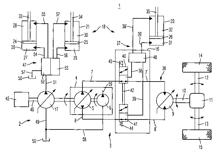
Figure 1 is a schematic illustration of the hydrostatic
drive according to the invention.
The hydrostatic drive 1 according to the invention
5 comprises an open circuit 2 and a closed circuit 3. In the
closed hydraulic circuit 3 there is provided a hydraulic
pump unit 4 which has an adjustable hydraulic pump 5. The
adjustable hydraulic pump 5 is coupled to the hydraulic
pump unit 4 by means of a supply pump 6. The hydraulic pump
5 is provided to produce a supply flow in the closed
hydraulic circuit 3 and is connected to a first operating
line 7 and a second operating line 8. The hydraulic pump 5
is configured to supply in both directions.
Before setting out the development of a travel drive
according to the invention, the travel drive as known per
se for utility vehicles should first be described. The
closed hydraulic circuit 3 comprises a hydraulic motor 9 in
addition to the hydraulic pump 5, the first operating line
7' and the second operating line 8'. In the embodiment
illustrated, the hydraulic motor 9 is adjustable in terms
of the intake volume thereof and is connected to the first
operating line 7 and the second operating line 8 and
consequently to the hydraulic pump 5 by means of a first
operating line portion 7' and a second operating line
portion 8'.
The hydraulic motor 9 is connected to a differential gear
11 by means of an output shaft 10. The differential gear 11
is, for example, a rear axle gear of a mobile operating
machine. In order to drive the vehicle, the torque supplied
to the differential gear 11 acts on a first and a second
CA 02625203 2008-04-07
6
drive wheel 14, 15 by means of a first half-shaft 12 and a
second half-shaft 13.
As described above, the connection of the hydraulic motor 9
to the hydraulic pump 5 is carried out via a first
operating line 7 and a first operating line portion 7' and
via a second operating line 8 and a second operating line
portion 8'. The connection between the first operating line
7 and the first operating line portion 7' and the second
operating line 8 and the second operating line portion 8'
is carried out by means of a valve device which is arranged
in a valve unit 16. The structure of the valve unit 16 is
described in greater detail below.
In addition to the hydraulic pump 5 of the closed hydraulic
circuit 3, an additional hydraulic pump 17 is provided and
is arranged in the open circuit 2. The additional hydraulic
pump 17 is also adjustable in terms of the supply volume
thereof but configured to supply in only one direction. In
addition to the travel drive, a hydraulic operating unit 18
is activated by the overall hydrostatic drive 1. In the
embodiment illustrated, the hydraulic operating unit 18
comprises a first hydraulic cylinder 20, a second hydraulic
cylinder 21 and a third hydraulic cylinder 23. The first
and the second hydraulic cylinder 20, 21 are acted on with
pressure medium by the additional hydraulic pump 17 of the
open hydraulic circuit 2. However, the third hydraulic
cylinder 23 is associated with the closed hydraulic circuit
3 and is coupled to the hydraulic pump 5 via the valve unit
16 as long as the closed hydraulic circuit 3 is not
required for the travel drive.
CA 02625203 2008-04-07
7
The first hydraulic cylinder 20 is constructed in the
embodiment illustrated as a dual-action lifting cylinder, a
piston 24 being arranged in the first hydraulic cylinder 20
and dividing the first hydraulic cylinder 20 into a piston
face space 27 and a piston rod space 28. Accordingly, a
second piston 25 is provided in the second hydraulic
cylinder 21 and again divides the second hydraulic cylinder
21 into a piston face space 29 and a piston rod space 30.
The third hydraulic cylinder 23 which is associated with
the closed hydraulic circuit 3 accordingly has a piston 26
which is arranged so as to be able to be longitudinally
displaced in the third hydraulic cylinder 23. Owing to the
piston 26, the hydraulic cylinder 23 is also divided into a
piston face space 31 and a piston rod space 32. The pistons
24, 25 and 26 can each be acted on with an adjustment
pressure at the side of the piston face space 27, 29 and 31
and at the face orientated in the opposite direction in the
piston rod space 28, 30, 32. The adjustment pressure for
the first operating cylinder 20 and the second operating
cylinder 21 is produced by means of the open hydraulic
circuit 2 or the additional hydraulic pump 17 which is
arranged therein. However, in order to activate the third
hydraulic cylinder 23, pressure is produced by the
hydraulic pump 5. In order to transfer the movement of the
pistons 24, 25 and 26 produced owing to the pressure
relationships in the piston face spaces or piston rod
spaces 27 to 32, for example, to an extension arm of a
crane lorry, the pistons 24, 25 and 26 are connected to the
component to be controlled by means of piston rods 33, 34,
35, respectively.
CA 02625203 2008-04-07
8
According to a preferred configuration, the closed
hydraulic circuit 3 is formed alternately by a travel
circuit 36 or an operating circuit 37. The components of
the travel circuit 36 have already been discussed above and
the circuit comprises the first operating line branch 7',
the hydraulic pump 9 and the second operating line branch
8'. The travel circuit 36 forms, together with the first
operating line 7 and the second operating line 8 and the
hydraulic motor 5, the closed hydraulic circuit 3, if a
travel operation is required.
The operating circuit 37 comprises, in addition to the
third hydraulic cylinder 23, a first consumer line 38 and a
second consumer line 39 which can be connected to the first
operating line 7 and the second operating line 8 by means
of the valve device of the valve unit 16. As long as the
vehicle is stationary, it is possible to switch between the
operating circuit 37 and the travel circuit 36. To this
end, a first switching valve 40 and a second switching
valve 41 are preferably arranged in the valve unit 16 and
form the valve device. The first switching valve 40 and the
second switching valve 41 are connected to each other by
means of a coupling rod 42 so that common activation is
possible. In the initial position of the first switching
valve 40 and the second switching valve 41 illustrated in
Figure 1, the first operating line 7 is connected to the
first operating line portion 7'. At the same time, the
second operating line 8 is connected to the second
operating line portion 8'.
In order to switch to the operating circuit 37, an
electromagnetic activation is provided on the first
switching valve 40. To this end, the first switching valve
CA 02625203 2008-04-07
9
40 is acted on in the direction of the second switching
position thereof by means of an electromagnet 43. The
movement which the electromagnet 40 produces in the first
switching valve 40 is transmitted by means of the coupling
rod 42 to the second switching valve 42 which is
consequently also displaced into the second switching
position thereof. The movement at the first switching valve
40 and the second switching valve 41 is carried out counter
to a pressure spring 44 which is provided on the second
switching valve 42. If the electromagnet 43 is no longer
supplied with electrical power, the second switching valve
41 and consequently the first switching valve 40 is brought
into the first switching position thereof again by means of
the pressure spring 44. In the second switching position of
the first switching valve 40 and the second switching valve
41, the first operating line 7 is connected to the first
consumer line 38. At the same time, the second operating
line 8 is connected to the second consumer line 39 by means
of the second switching valve 41.
In the embodiment illustrated, the first switching valve 40
and the second switching valve 41 are provided purely for
switching between the travel circuit 36 and the operating
circuit 37. The control of the electromagnet 43 can
therefore advantageously be coupled, for example, to an
idle sensor. The association of the piston face space 31
and the piston rod space 32 of the third hydraulic cylinder
23 is, however, carried out by means of an association
valve unit 48 which is preferably also arranged in the
valve unit 16. In order to associate the piston rod space
32 or the piston face space 31 with the first operating
line 7 or with the second operating line 8, the association
valve unit 48 connects either a first consumer line branch
CA 02625203 2008-04-07
38' to the first consumer line 38 and at the same time a
second consumer line branch 39' to the second consumer line
39 or the first consumer line branch 38' to the second
consumer line 39 and the second consumer line branch 39' to
5 the first consumer line 38. The association valve unit 28
can preferably also be produced with simple switching
valves. The adjustment speed and the adjustment direction
are determined by the variable hydraulic pump 5 being
adjusted.
The open hydraulic circuit 2 comprises, in addition to the
additional hydraulic pump 17, an intake line 49. The
additional hydraulic pump 17 draws pressure medium from a
tank space 50 via the intake line 49 and conveys it into a
supply line 51. In order to produce an adjustment pressure
in the piston face space 27 or the piston rod space 28 of
the first hydraulic cylinder 20, the supply line 51 can be
connected to a first connection line 54 or a second
connection line 55 by means of a first adjustment valve
unit 52. Accordingly, it is also possible to convey
pressure medium from the supply line 51 into the piston
face space 29 or the piston rod space 30 of the second
hydraulic cylinder 21 via a third connection line 56 or a
fourth connection line 57. The connection of the third
connection line 56 or the fourth connection line 57 to the
supply line 51 is carried out by means of a second valve
unit 53. The first valve unit 52 and the second valve unit
53 are preferably integrated in a common housing. In place
of a connection of the supply line 51 to one of the
connection lines 54 to 57, it is also possible to produce a
connection to a depressurisation line 57 by means of the
valve units 52, 53.
CA 02625203 2008-04-07
11
If, for example, a lifting movement of the piston 24 of the
first hydraulic cylinder 20 is intended to be carried out
by applying pressure to the piston face space 27, the first
connection unit 54 is connected to the supply line 51 by
means of the first valve unit 52. At the same time, in
order to allow volume compensation, the second connection
line 55 of the piston rod space 28 is connected to the
depressurisation line 57. The pressure medium forced from
the piston rod space 28 is consequently discharged into the
tank space 50.
The activation of the second hydraulic cylinder 21 is
carried out in the same manner, so that it is not necessary
to describe this again. The first valve unit 52 and the
second valve unit 53 can be controlled together or
separately and are connected to the supply line 51 and the
depressurisation line 57 by means of common connections.
A common drive motor 45 is used in order to drive the
hydraulic pumps 5, 6, 17 and is coupled to the hydraulic
pumps 5, 6, 17 by means of a drive shaft 46.
In order to produce an initial system pressure, as
described above, a supply pump 6 is provided in the
hydraulic pump unit 4 in addition to the hydraulic pump 5.
The supply pump 6 also draws pressure medium from the tank
space 50 via a supply pump intake line 58 and conveys it to
a supply pressure system (not illustrated) via a supply
pressure line 59.
In place of the hydraulic cylinder illustrated, it is also
possible to use any other hydraulic consumer. In
particular, the individual hydraulic consumers of the
CA 02625203 2008-04-07
12
hydraulic operating unit 18 do not have to have the same
configuration. However, it is particularly advantageous to
provide a hydraulic cylinder which is generally only acted
on with pressure in the closed hydraulic circuit 3. In this
instance, it is possible to recover energy, for example,
when pressure is applied to the piston rod 35 of the third
hydraulic cylinder 23. The weight which presses on the
piston rod 35 produces in the piston face space 31 a
pressure which is supplied to the hydraulic pump 5 via the
second consumer line branch 39' and the valve unit 16 and
is supported at that location. Consequently, the hydraulic
pump 5 operates as a hydraulic motor and produces a torque
which is supplied to the additional hydraulic pump 17 via
the drive shaft 46. The common drive engine 45 consequently
has to produce only a reduced level of torque to drive the
additional hydraulic pump 17, whereby the fuel consumption
of the drive motor 45 decreases.
In order to retain a load which has been lifted using the
third hydraulic cylinder 23, a load retaining valve is
preferably arranged in the association valve unit 48 and
disengages the connection between the first and second
consumer line branch 38', 39' and the first consumer line
38 and the second consumer line 39. In order to remove
pressure medium from the closed circuit 3, a flush valve
can preferably also be integrated in the common valve unit
16 which in particular contains all the valves required to
operate the travel circuit 36 and the operating circuit 37.
The invention is not limited to the embodiment illustrated.
In particular, under combinations of individual features as
they have been explained in the description above are
possible without having to implement all the features
CA 02625203 2008-04-07
13
explained.