Sélection de la langue

Search

Sommaire du brevet 2625490 

Énoncé de désistement de responsabilité concernant l'information provenant de tiers

Une partie des informations de ce site Web a été fournie par des sources externes. Le gouvernement du Canada n'assume aucune responsabilité concernant la précision, l'actualité ou la fiabilité des informations fournies par les sources externes. Les utilisateurs qui désirent employer cette information devraient consulter directement la source des informations. Le contenu fourni par les sources externes n'est pas assujetti aux exigences sur les langues officielles, la protection des renseignements personnels et l'accessibilité.

Disponibilité de l'Abrégé et des Revendications

L'apparition de différences dans le texte et l'image des Revendications et de l'Abrégé dépend du moment auquel le document est publié. Les textes des Revendications et de l'Abrégé sont affichés :

  • lorsque la demande peut être examinée par le public;
  • lorsque le brevet est émis (délivrance).
(12) Brevet: (11) CA 2625490
(54) Titre français: INDICATEUR DE DIRECTION, SPECIALEMENT INDICATEUR DE SORTIE DE SECOURS SUR LE SOL OU SUR UN MUR
(54) Titre anglais: PATHWAY MARKER, ESPECIALLY FIRE ESCAPE MARKER IN A FLOOR OR WALL
Statut: Périmé et au-delà du délai pour l’annulation
Données bibliographiques
(51) Classification internationale des brevets (CIB):
  • G09F 13/20 (2006.01)
  • C09K 11/00 (2006.01)
  • E04F 13/08 (2006.01)
  • E04F 15/02 (2006.01)
  • G09F 13/22 (2006.01)
(72) Inventeurs :
  • PARKKARI, JORMA (Finlande)
(73) Titulaires :
  • JORMA PARKKARI
(71) Demandeurs :
  • JORMA PARKKARI (Finlande)
(74) Agent: MARKS & CLERK
(74) Co-agent:
(45) Délivré: 2014-07-29
(86) Date de dépôt PCT: 2006-10-05
(87) Mise à la disponibilité du public: 2007-04-12
Requête d'examen: 2011-09-21
Licence disponible: S.O.
Cédé au domaine public: S.O.
(25) Langue des documents déposés: Anglais

Traité de coopération en matière de brevets (PCT): Oui
(86) Numéro de la demande PCT: PCT/FI2006/050430
(87) Numéro de publication internationale PCT: FI2006050430
(85) Entrée nationale: 2008-04-07

(30) Données de priorité de la demande:
Numéro de la demande Pays / territoire Date
20055539 (Finlande) 2005-10-06

Abrégés

Abrégé français

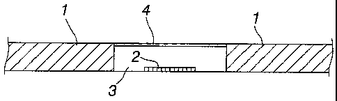
La présente invention concerne un indicateur de direction, en particulier un indicateur de parcours de sortie de secours sur le sol ou sur un mur. Un tel indicateur de direction autoluminescent (2) est disposé au dessus et/ou en-dessous d'une ou plusieurs couches de substrat (3, 5) contenues dans l'indicateur de direction, ou bien la couche de substrat elle-même constitue un indicateur de direction autoluminescent. Sur le dessus de la couche de substrat (3, 5) est tracé un motif quadrillé (4) du type désiré, dissimulant partiellement l'indicateur de direction et à travers lequel l'indicateur de direction autoluminescent (2) est partiellement visible.


Abrégé anglais


The invention relates to a pathway marker, especially a fire escape route
marker in a floor or wall. A self-luminescent
pathway marker (2) is overlaid and/or underlaid with one or more substrate
layers (3, 5) included in the pathway marker, or the very
substrate layer constitutes a self-luminescent pathway marker. On top of the
substrate layer (3, 5) is a raster pattern (4) of desired
type, partially concealing the pathway marker and having the self-luminescent
pathway marker (2) partially visible therethrough.

Revendications

Note : Les revendications sont présentées dans la langue officielle dans laquelle elles ont été soumises.


6
The embodiments of the invention in which an exclusive property or
privilege is claimed are defined as follows:
1. A pathway marker, comprising a self-luminescent pathway marker and a
substrate layer, which is underlaid with the pathway marker or which substrate
layer constitutes the self-luminescent pathway marker, wherein the substrate
layer is transparent glass, plastics or resin and is overlaid with
a raster or line pattern of desired type partially concealing the pathway
marker, the self-luminescent pathway marker being partially visible through
the
pattern; or
a skin concealing the pathway marker and having been treated to be
partially transmissive to light or scattering light, and partially blocking or
screening visual perception of a photoluminescent material in lighted or
illuminated conditions.
2. A pathway marker as set forth in claim 1, wherein the raster or line
pattern
or the skin provides the substrate layer's top or outer skin serving as part
of a
floor or wall surface.
3. A pathway marker as set forth in claim 1 or 2, wherein the raster or
line
pattern or the skin is pressed to the substrate layer's skin by a silk screen
printing
method.
4. A pathway marker as set forth in any one of claims 1 to 3, wherein the
raster or line pattern or the skin is pressed to the outer surface of a glass
or
plastic sheet included in the substrate layer.
5. A pathway marker as set forth in claim 1, wherein the raster or line
pattern
or the skin is pressed to a plastic film which is bonded to the substrate
layer or
lies between the substrate layers.

7
6. A pathway marker as set forth in any one of claims 1 to 5, wherein the
pathway marker is accommodated in a recess present in a panel included in the
substrate layer.
7. A pathway marker as set forth in any one of claims 1 to 6, wherein
alongside the pathway marker is a reflector surface located under the raster
or
line pattern or the skin.
8. A pathway marker as set forth in any one of claims 1 to 3, wherein the
substrate layer comprises a block of building material, and that the block
material
has a luminescent material disbursed therein.
9. A pathway marker as set forth in any one of claims 1 to 8, wherein the
pathway marker, along with its substrate layer and raster or line pattern or
the
skin, provides a sandwich structure having its thickness substantially equal
to
that of a floor or wall tile.
10. A pathway marker as set forth in claim 9, wherein said sandwich
structure
is assembled for an integral block, which is installable in an opening cut in
the tile
or which replaces a tile used as the surface layer of a floor or wall.
11. A pathway marker as set forth in claim 1 or 2, wherein the raster or
line
pattern or the skin is adapted according to the appearance of the surrounding
surface pattern.
12. A pathway marker as set forth in any one of claims 1 to 11, wherein the
pathway marker is a fire escape route marker in a floor or wall.

Description

Note : Les descriptions sont présentées dans la langue officielle dans laquelle elles ont été soumises.


CA 02625490 2008-04-07
WO 2007/039673 PCT/F12006/050430
1
Pathway marker, especially fire escape marker in a floor or wall
The invention relates to a pathway marker, especially a fire escape route
marker in
a floor or wall, comprising a self-luminescent pathway marker and a substrate
layer,
which is overlaid and/or underlaid with one or more pathway markers and which
substrate layer constitutes the self-luminescent pathway marker.
The publication WO 9857315 discloses a tile type building material, having
incorporated therein a guide or the like informational pattern of a self-
luminescent
or fluorescent material. The application publication US-2003/215596 also
discloses a
floor tile provided with a self-luminescent pathway marking. A drawback in
these
prior known solutions is that such indicia are aesthetically disturbing and,
thus, have
not gained widespread popularity.
The publication US 2003/0215596 A1 discloses a pathway marker, wherein a
photoluminescent material is disbursed within a tile base and these tiles are
used to
provide a marker blending into surroundings under normal lighting. A problem
is
how to apply the manufacturing method to all various types of building
materials.
Another problem is that in lighted or illuminated conditions the pathway
marker
does not have a capability of providing a figure in desired colour or shape.
It is an object of the invention to provide an improved pathway marker, which
in
lighted or illuminated conditions is visible as a figure in desired colour or
shape or, if
desired, is nearly imperceptible in the most diverse of floor or wall
surfaces.
This object is accomplished by the invention in such a way that the substrate
layer
is overlaid with
- a raster or line pattern of desired type partially concealing the pathway
marker,
the self-luminescent pathway marker being partially visible through the
pattern,
and/or
- a skin concealing the pathway marker and having been treated to be partially
transmissive to light or scattering light, and partially blocking or screening
visual
perception of a photoluminescent material in lighted or illuminated
conditions.

CA 02625490 2014-01-17
2
In normal lighting, the raster or line pattern or the skin provides an
ambience-
blending figure, but in the dark the pathway markers are clearly visible
through the
raster or line pattern or the skin. As desired, the raster or line pattern or
the skin
may provide an intentionally distinctive strip, but in the dark the pathway
marker
visible from under the raster pattern provides a guiding line and/or a
sequence of
arrows or some other pathway marker highly visible on a floor or wall.
According to an aspect of the present invention there is provided a pathway
marker,
comprising a self-luminescent pathway marker and a substrate layer, which is
underlaid with the pathway marker or which substrate layer constitutes the
self-
luminescent pathway marker, wherein the substrate layer is transparent glass,
plastics or resin and is overlaid with
a raster or line pattern of desired type partially concealing the pathway
marker, the self-luminescent pathway marker being partially visible through
the
pattern; or
a skin concealing the pathway marker and having been treated to be
partially transmissive to light or scattering light, and partially blocking or
screening
visual perception of a photoluminescent material in lighted or illuminated
conditions.
The dependent claims disclose preferred embodiments of the invention.
The invention will now be described in more detail by way of exemplary
embodiments with reference to the accompanying drawings, in which
Fig. 1 is a sectional view of a tile, which is useful as a floor or wall
surface
and which carries a pathway marker according to one embodiment of
the invention;
Fig. 2 is a sectional view of a tile, which carries a pathway marker
according to a second embodiment of the invention;
Fig. 3 is a plan view of a raster pattern according to one embodiment of
the
invention;
Fig. 4 shows a raster pattern of another embodiment, which imitates the
surface appearance of a surrounding tile; and

CA 02625490 2014-01-17
2a
Figs. 5 and 6 are further sectional views of tiles provided with pathway
markers
according to feasible embodiments of the invention.
In the example of fig. 1, a floor or wall skin layer 1, e.g. a tile floor 1,
has been cut
for an opening which is elongated in the direction normal to the drawing's
plane.
The opening is fitted with a panel 3 of glass or plastics, having a recess in
its bottom
surface provided with a pathway marker 2 of a self-luminescent material
(photoluminescent material). The pathway marker 2 can be a long line running
from
tile to tile, including directional arrow points at appropriate distances. The
pathway
marker 2 may also consist of arrows appropriately spaced in individual tiles.
The
panel 3 has its top surface formed, e.g. by a silk screen printing method,
with a

CA 02625490 2008-04-07
WO 2007/039673 PCT/F12006/050430
3
raster pattern 4 imitating the appearance of the tile's 1 surface or being
otherwise
as desired. Figs. 3 and 4 illustrate examples of raster patterns, imitating
the skin of
lithic tiles. The raster pattern 4 can be any figure in desired colour and
shape, which
is visible in luminous conditions yet disappears in the dark, thus visualizing
a
pathway marker partially concealed by the raster pattern.
As a raster pattern is pressed by a silk screen printing method with an enamel
material to glass surface, the pattern can be fired in a kiln for a wear-
resistant skin
functional as part of a floor surface. The pathway marker 2 can also be
located at
the substrate layer's 3 top surface, directly under the raster pattern 4. The
substrate layer 3 does not necessarily require a recess for the pathway marker
2.
The pathway marker 2 can be e.g. an adhesive tape of a self-luminescent
material
or coated with a self-luminescent material, which is fastened to the substrate
layer's
3 surface. The pathway marker 2 can also be made of a 2-component compound,
typically as a layer of about 0,5-2 mm in thickness, which does not
necessarily
require a recess in the substrate layer 3.
Fig. 2 illustrates an alternative solution, which differs from the former in
the sense
that the substrate layer 3 consists of two superimposed sheets 3a, 3b, the
pathway
marker 2 being fitted therebetween. The pathway marker 2 extends across the
entire width of the substrate layer 3, which is the case also in fig. 5.
In the exemplary embodiments of figs. 5 and 6, the raster pattern 4 is further
covered with a protective skin 5 that can be of glass, plastics or resin. In
this case,
the raster pattern 4 may be pressed to a plastic film accommodated between the
sheets 3 and 5. Most preferably, however, the raster pattern is pressed
directly to
the sheet's 3a, 3b top surface which is substantially coplanar with the tile
layer's 1
outer surface. Thus, there will be no extra glossy surface layer 5, the
surface being
as uniform as possible. Hence, the sheets 3 and 5 constitute a supporting
substrate
layer both for the pathway marker 2 and the raster pattern 4.
The example of fig. 6 differs from fig. 5 in the sense that the pathway marker
2 is
accommodated between a stiff transparent panel 3b and a base panel 3a, the
former being included in the substrate layer. The base panel 3a need not be
transparent and it can also be a part of the tile 1, the inventive pathway
marker

CA 02625490 2008-04-07
WO 2007/039673 PCT/F12006/050430
4
being accommodated in a recess present in the tile 1. This is possible in
other
exemplary embodiments as well. Alongside the pathway marker 2, on one or
either
side thereof, is a reflector surface 6 which is also located under the raster
pattern 4.
The reflector 6 enhances the visual perception of a pathway marker, when
illuminated e.g. with a flashlight or in the event that the space has been in
darkness
for a long time and the self-luminescent ability of the directional marking
has
decayed accordingly. The reflector surface can be used in other exemplary
embodiments as well.
The pathway marker 2, along with its substrate layers 3, 5 and raster pattern
4 and
possible base panel 3a, may constitute a sandwich structure equal in thickness
to
the floor or wall tile 1. This sandwich structure may be assembled for an
integral
block. The block can also be installable in an opening or recess cut in the
tile 1.
Optionally, the substrate sandwich structure can be made at least partially by
in-situ
casting, e.g. of resin. Feasible as the substrate layer sheets 3, 3a, 3b, 5 is
polycarbonate panel and/or tempered glass. The substrate layer and the pathway
marker can also be combined, e.g. by having a photoluminescent material
disbursed
within the material of a building tile, whereby the tile is glowing as a
whole. The
overlaid raster pattern 4 provides a marker visible in lighted or illuminated
conditions.
The foregoing description deals with the invention in reference to floors or
walls
clad with tiles, such as lithic tiles. Other patterned surface material may
also be
relevant, for example parquet or board in floors or panel or wallpaper in
walls.
In the drawings, the raster pattern 4 has its thickness exaggerated for the
sake of
clarity. The raster pattern 4 has its dots, lines or pixels in other shapes,
which make
up a desired figure, concealing 20-80%, preferably 40-60% of the pathway
marker's area. Thus, in lighted or illuminated conditions, it is possible to
provide any
desired surface pattern, including a pathway marker or an interior ornament
which
disappears in the dark, and the pathway marker, which may be a figure as well,
emerges as a glowing colour.
A raster pattern is economically viable and good for various applications. In
some
cases, the same object of the invention is also achieved by a second
embodiment of

CA 02625490 2008-04-07
WO 2007/039673 PCT/F12006/050430
the invention, in which the substrate layer is covered by a pathway-marker
concealing skin treated for partially transmitting light (to be partially
translucent) or
for scattering light and blocking the visual perception of a photoluminescent
material in lighted or illuminated conditions. A partially light transmitting
or
translucent skin can be made e.g. from a thin, semi-translucent colour
membrane. A
light scattering skin is obtained by using e.g. a sand-blasted glass surface
or some
other transparent material layer with its surface roughened for scattering of
light.
The invention can be applied e.g. in marking systems for exit routes and fire
escapes. The invention has its functionality based on having a partially
translucent
skin pattern. Consequently, a post-luminescent material in the bottom part of
a
body absorbs energy in itself, releasing it in the dark as glowing light. The
skin
pattern can be produced by various raster patterns that can be regular or
irregular,
mono- or polychromatic and have a translucency that can be regulated as
desired.
By using the raster or line pattern or the translucent skin it is possible to
create
desired architectural patterns. In many buildings it is desired that the
raster or line
pattern or the translucent skin is adapted according to appearance of the
surrounding surface pattern, preferably by imitating one or more
characteristic
feature of the appearance of the surrounding surface. In the latter case, the
image
of the raster or line pattern or the skin would resemble, at least to some
extend,
the image of the surrounding surface.

Dessin représentatif
Une figure unique qui représente un dessin illustrant l'invention.
États administratifs

2024-08-01 : Dans le cadre de la transition vers les Brevets de nouvelle génération (BNG), la base de données sur les brevets canadiens (BDBC) contient désormais un Historique d'événement plus détaillé, qui reproduit le Journal des événements de notre nouvelle solution interne.

Veuillez noter que les événements débutant par « Inactive : » se réfèrent à des événements qui ne sont plus utilisés dans notre nouvelle solution interne.

Pour une meilleure compréhension de l'état de la demande ou brevet qui figure sur cette page, la rubrique Mise en garde , et les descriptions de Brevet , Historique d'événement , Taxes périodiques et Historique des paiements devraient être consultées.

Historique d'événement

Description Date
Le délai pour l'annulation est expiré 2024-04-05
Lettre envoyée 2023-10-05
Lettre envoyée 2023-04-05
Lettre envoyée 2022-10-05
Remise non refusée 2022-01-21
Lettre envoyée 2021-12-21
Offre de remise 2021-12-21
Requête visant le maintien en état reçue 2021-09-09
Requête visant le maintien en état reçue 2020-08-26
Requête visant le maintien en état reçue 2019-11-20
Représentant commun nommé 2019-10-30
Inactive : Paiement - Taxe insuffisante 2019-10-21
Requête visant le maintien en état reçue 2019-10-08
Lettre envoyée 2019-10-07
Accordé par délivrance 2014-07-29
Inactive : Page couverture publiée 2014-07-28
Préoctroi 2014-05-12
Inactive : Taxe finale reçue 2014-05-12
Lettre envoyée 2014-03-18
Un avis d'acceptation est envoyé 2014-03-18
Inactive : Approuvée aux fins d'acceptation (AFA) 2014-03-14
Inactive : QS réussi 2014-03-14
Modification reçue - modification volontaire 2014-01-17
Inactive : Dem. de l'examinateur par.30(2) Règles 2013-07-18
Modification reçue - modification volontaire 2012-03-02
Lettre envoyée 2011-10-04
Requête d'examen reçue 2011-09-21
Exigences pour une requête d'examen - jugée conforme 2011-09-21
Toutes les exigences pour l'examen - jugée conforme 2011-09-21
Requête visant une déclaration du statut de petite entité reçue 2011-09-21
Modification reçue - modification volontaire 2011-09-21
Inactive : Page couverture publiée 2008-10-02
Inactive : Notice - Entrée phase nat. - Pas de RE 2008-09-30
Inactive : Inventeur supprimé 2008-09-30
Inactive : CIB en 1re position 2008-04-30
Demande reçue - PCT 2008-04-29
Exigences pour l'entrée dans la phase nationale - jugée conforme 2008-04-07
Déclaration du statut de petite entité jugée conforme 2008-04-07
Demande publiée (accessible au public) 2007-04-12

Historique d'abandonnement

Il n'y a pas d'historique d'abandonnement

Taxes périodiques

Le dernier paiement a été reçu le 2014-06-09

Avis : Si le paiement en totalité n'a pas été reçu au plus tard à la date indiquée, une taxe supplémentaire peut être imposée, soit une des taxes suivantes :

  • taxe de rétablissement ;
  • taxe pour paiement en souffrance ; ou
  • taxe additionnelle pour le renversement d'une péremption réputée.

Les taxes sur les brevets sont ajustées au 1er janvier de chaque année. Les montants ci-dessus sont les montants actuels s'ils sont reçus au plus tard le 31 décembre de l'année en cours.
Veuillez vous référer à la page web des taxes sur les brevets de l'OPIC pour voir tous les montants actuels des taxes.

Historique des taxes

Type de taxes Anniversaire Échéance Date payée
Taxe nationale de base - petite 2008-04-07
TM (demande, 2e anniv.) - petite 02 2008-10-06 2008-04-07
TM (demande, 3e anniv.) - petite 03 2009-10-05 2009-09-29
TM (demande, 4e anniv.) - petite 04 2010-10-05 2010-09-08
TM (demande, 5e anniv.) - petite 05 2011-10-05 2011-09-06
Requête d'examen - petite 2011-09-21
TM (demande, 6e anniv.) - petite 06 2012-10-05 2012-09-13
TM (demande, 7e anniv.) - petite 07 2013-10-07 2013-10-03
Taxe finale - petite 2014-05-12
TM (demande, 8e anniv.) - petite 08 2014-10-06 2014-06-09
TM (brevet, 9e anniv.) - petite 2015-10-05 2015-09-04
TM (brevet, 10e anniv.) - petite 2016-10-05 2016-09-26
TM (brevet, 11e anniv.) - petite 2017-10-05 2017-09-25
TM (brevet, 12e anniv.) - petite 2018-10-05 2018-09-24
TM (brevet, 13e anniv.) - petite 2019-10-07 2019-10-08
Annulation de la péremption réputée 2019-10-07 2019-10-08
TM (brevet, 14e anniv.) - petite 2020-10-05 2020-08-26
TM (brevet, 15e anniv.) - petite 2021-10-05 2021-09-09
Titulaires au dossier

Les titulaires actuels et antérieures au dossier sont affichés en ordre alphabétique.

Titulaires actuels au dossier
JORMA PARKKARI
Titulaires antérieures au dossier
S.O.
Les propriétaires antérieurs qui ne figurent pas dans la liste des « Propriétaires au dossier » apparaîtront dans d'autres documents au dossier.
Documents

Pour visionner les fichiers sélectionnés, entrer le code reCAPTCHA :


Pour visualiser une image, cliquer sur un lien dans la colonne description du document (Temporairement non-disponible). Pour télécharger l'image (les images), cliquer l'une ou plusieurs cases à cocher dans la première colonne et ensuite cliquer sur le bouton "Télécharger sélection en format PDF (archive Zip)" ou le bouton "Télécharger sélection (en un fichier PDF fusionné)".

Liste des documents de brevet publiés et non publiés sur la BDBC .

Si vous avez des difficultés à accéder au contenu, veuillez communiquer avec le Centre de services à la clientèle au 1-866-997-1936, ou envoyer un courriel au Centre de service à la clientèle de l'OPIC.

({010=Tous les documents, 020=Au moment du dépôt, 030=Au moment de la mise à la disponibilité du public, 040=À la délivrance, 050=Examen, 060=Correspondance reçue, 070=Divers, 080=Correspondance envoyée, 090=Paiement})


Description du
Document 
Date
(aaaa-mm-jj) 
Nombre de pages   Taille de l'image (Ko) 
Description 2008-04-06 5 232
Revendications 2008-04-06 2 73
Dessins 2008-04-06 3 153
Dessin représentatif 2008-04-06 1 3
Abrégé 2008-04-06 1 54
Revendications 2011-09-20 2 74
Description 2014-01-16 6 251
Revendications 2014-01-16 2 72
Dessin représentatif 2014-07-06 1 4
Avis d'entree dans la phase nationale 2008-09-29 1 193
Rappel - requête d'examen 2011-06-06 1 120
Accusé de réception de la requête d'examen 2011-10-03 1 176
Avis du commissaire - Demande jugée acceptable 2014-03-17 1 161
Avis de paiement insuffisant pour taxe (anglais) 2019-10-20 1 90
Avis concernant la taxe de maintien 2019-10-20 1 177
Avis du commissaire - Non-paiement de la taxe pour le maintien en état des droits conférés par un brevet 2022-11-15 1 540
Courtoisie - Brevet réputé périmé 2023-05-16 1 546
Avis du commissaire - Non-paiement de la taxe pour le maintien en état des droits conférés par un brevet 2023-11-15 1 550
PCT 2008-04-06 3 77
Correspondance 2011-09-20 2 46
Correspondance 2014-05-11 1 34
Paiement de taxe périodique 2019-10-07 1 35
Paiement de taxe périodique 2019-11-19 1 28
Paiement de taxe périodique 2020-08-25 3 125
Paiement de taxe périodique 2021-09-08 1 29
Courtoisie - Lettre de remise 2021-12-20 2 203