Note : Les descriptions sont présentées dans la langue officielle dans laquelle elles ont été soumises.
CA 02627500 2011-06-14
WH-10322CA
SN 2,627',500
SHAFT MEMBER COUPLING STRUCTURE
FIELD OF THE INVENTION
The present invention relates to shaft member coupling structure for lockably
coupling two shaft members in a condition in which they are coaxially extended
with a coupling part in the center. Further detailedly, the invention relates
to shaft
member coupling structure which can be applied to a spool valve forming a
clutch
valve of a hydrostatic continuously variable transmission.
BACKGROUND OF THE INVENTION
As for a hydrostatic continuously variable transmission, configurations of
various
types have been known and have been realized. For example, hydrostatic
continuously variable transmissions have been proposed and disclosed in JP-A
No.
H6-42446, JP Patent No. 2920772, JP-A No. H9-100909, and JP-A No. 2005-256979
by
this applicant. These hydrostatic continuously variable transmissions
disclosed in
JP-A No. H6-42446, JP Patent No. 2920772, JP-A No. H9-100909, and JP-A No.
2005-
256979 are each provided with a awash plate type plunger pump, a awash plate
type
plunger motor and a hydraulic closed circuit that connects a discharge port
and a
suction port of the swash plate type plunger pump to a suction port and a
discharge
port of the awash plate type plunger motor, is configured so that a pump awash
plate is driven by an engine, a pump cylinder and a motor cylinder are
connected
and are arranged on an output shaft, the rotation of a motor awash plate is
regulated, and an angle of the motor awash plate can be variably adjusted.
CA 02627500 2008-03-25
-2-
It has been also known that in the hydrostatic continuously variable
transmission
configured as described above, a clutch valve that connects and cuts off an
oil
passage on the high pressure side and an oil passage on the low pressure side
respectively forming the hydraulic closed circuit is provided, quantity in
which
rotational driving force from the hydraulic pump is transmitted to the
hydraulic
motor is controlled and clutch control that cuts off this rotational
transmission is
executed. For example, in JP-A No. 2005-256979, an automatic clutch using such
a clutch valve is disclosed. This clutch valve is provided with a valve spool
movably arranged in a spool hole axially extended in the supporting shaft that
rotatably supports the hydraulic pump and the hydraulic motor, and connects
and cuts off the oil passage on the high pressure side and the oil passage on
the
low pressure side by axially moving the valve spool. The clutch valve is
provided with a spring (energizing means) that energizes the valve spool in a
direction of disengagement and a centrifugal governor that generates force
corresponding to input revolution speed, is opened and closed according to
balance among energizing force by the spring, governor force and a load
depending upon internal pressure (high pressure), and executes control for
connecting and cutting off the oil passage on the high pressure side and the
oil
passage on the low pressure side.
In the above-mentioned clutch valve, as the valve spool requires a part that
receives energizing force by the spring and governor force, a part that guides
to
enable axial smooth movement in the spool hole and a part that connects and
cuts off the oil passage on the high pressure side and the oil passage on the
low
pressure side according to the axial movement, the valve spool is formed in an
axially long shape. In this case, as high precision is required for the
peripheral
dimension of a guide part fitted into a guide hole formed in the supporting
shaft
and guided to be axially moved in the spool hole and the peripheral dimension
of a valve part fitted to a part in which the oil passage on the high pressure
side
and the oil passage on the low pressure side are open in the spool hole for
connecting and cutting off the oil passage on the high pressure side and the
oil
passage on the low pressure side according to the axial movement, the above-
mentioned clutch valve has a problem that the manufacture of the valve spool
is
WH-13322/cs
CA 02627500 2011-06-14
WH-13322CA - 3 -
SN 2,627,500
difficult and a great deal of manufacturing cost is required and a problem
that when
the precision is not met, operation performance may be deteriorated.
The inventors proposed that the valve spool be formed by coupling a first
spool
member provided with a part for forming the guide part and a second spool
member provided with a part for forming the valve part based upon the above-
mentioned problems. Further, the inventors proposed a configuration wherein
the
first spool member and the second spool member coaxially extend and are
mutually
lockably coupled by a coupling pin extending in a direction perpendicular to
the
axis as shaft member coupling structure. However, in this configuration, the
coupling pin is merely fitted into coupling holes extending in the direction
perpendicular to the axis in the first and second spool members and a problem
wherein the coupling pin falls away and may hinder rocking occurs. To prevent
this
problem, it is conceivable that the coupling pin is press-fitted into the
coupling
holes, however, a problem occurs wherein a press-fitted part may be broken
during
the press fitting and a problem occurs in that man-hours needed for press
fitting
increases.
The invention is made in view of such problems and its object is to provide
shaft
member coupling structure configured so that a coupling pin is fitted into
coupling
holes without press fitting and can be effectively and easily prevented from
falling
away.
SUMMARY OF THE INVENTION
Therefore, the shaft member coupling structure according to an embodiment of
the
present invention is based upon a shaft member coupling structure for lockably
coupling two shaft members in a condition in which they coaxially extend with
a
coupling part in the center, and is configured so that a fitting concave
portion axially
extends and is formed at the end of one shaft member. A fitting convex portion
axially extends and can be fitted into the fitting concave portion and is
formed at the
end of the other shaft member. A coupling pin is inserted into coupling holes
that
pierce the two shaft members in a direction perpendicular to the axis in the
part in
which the fitting concave portion and the fitting convex portion are fitted
and the
two shaft members are lockably coupled with the coupling pin in the center. In
CA 02627500 2011-06-14
WH-13322CA - 4 -
SN 2,627,500
addition, an annular holding groove concave in a circumferential direction is
formed in a part in which the coupling hole is formed on the periphery of the
shaft
member provided with the fitting concave portion and both ends of the coupling
pin inserted into the coupling holes are covered with each ring fitted into
each
holding groove.
In the shaft member coupling structure, it is desirable that the ring is
worked by .
bending wire in the shape of a ring and is formed in the shape of a axle by
lapping
and binding the ends of the wire.
In this case, it is desirable that the ring is formed in the shape of a coil
by winding
wire in the shape of a ring plural times.
Besides, it is desirable that the side of a part in which an end of the wire
is lapped of
the ring is worked and the ring is provided with slightly narrower width than
the
width of the holding groove overall.
According to the shaft member coupling structure configured as described
above,
according to an embodiment of the present invention, as the ring is fitted
into the
annular holding groove concave in the circumferential direction formed in the
part
in which the coupling hole is formed on the periphery of the shaft member
provided
with the fitting concave portion and covers both ends of the coupling pin
inserted
into the coupling holes based upon the configuration that the coupling pin is
inserted into the coupling holes that pierce the two shaft members in the
direction
perpendicular to the axis in the part in which the fitting concave portion and
the
fitting convex portion are fitted and the shaft members are lockably coupled
with
the coupling pin in the center, the coupling pin can be effectively prevented
from
falling away by the ring and the fitting of the ring can be also simplified.
30, When the ring is worked by bending the wire in the shape of a ring and is
formed in
the shape of a circle by lapping and binding the ends of the wire, the
manufacture is
easy and the ring can be easily fitted into the holding groove.
CA 02627500 2008-03-25
-5-
In this case, it is desirable that the ring is formed in the shape of a coil
by winding
the wire in the shape of a ring plural times and hereby, the ring can be
effectively
prevented from being detached from the holding groove.
When the side of the part in which the end of the wire is lapped is worked and
the ring is provided with slightly narrower width than the width of the
holding
groove overall, the ring can be securely fitted into the holding groove
without
rattling.
BRIEF DESCRIPTION OF THE DRAWINGS
Preferred embodiments of the invention are shown in the drawings, wherein:
Fig. 1 is a sectional view showing the configuration of a hydrostatic
continuously
variable transmission provided with a clutch to which shaft member coupling
structure according to the invention is applied.
Fig. 2 is an outside drawing showing a motorcycle provided with the
hydrostatic
continuously variable transmission.
Fig. 3 is a schematic drawing showing the power transmission path
configuration
of a power unit provided with the hydrostatic continuously variable
transmission.
Fig. 4 is a sectional view showing the configuration of the hydrostatic
continuously variable transmission.
Fig. 5 is a sectional view enlarged to show the configuration of a part of the
hydrostatic continuously variable transmission.
Fig. 6 is a sectional view enlarged to show the configuration of the part of
the
hydrostatic continuously variable transmission.
Fig. 7 is a front view and a sectional view showing a cotter used for
positioning a
rotor in the hydrostatic continuously variable transmission.
WH-13322/cs
CA 02627500 2008-03-25
-6-
Fig. 8 is a front view and a sectional view showing a retainer ring used for
positioning the rotor in the hydrostatic continuously variable transmission.
Fig. 9 is a front view and a sectional view showing a snap ring used for
positioning the rotor in the hydrostatic continuously variable transmission.
Fig. 10 is a sectional view showing a motor servo mechanism in the hydrostatic
continuously variable transmission.
Fig. 11 is a sectional view showing the structure of a hydraulic pump and a
clutch in the hydrostatic continuously variable transmission.
Fig. 12 is a sectional view showing the structure of a transmission output
shaft
and the output rotor in the hydrostatic continuously variable transmission.
Fig. 13 is a sectional view showing the structure of the transmission output
shaft
and the output rotor in the hydrostatic continuously variable transmission.
Fig. 14 is a sectional view showing the structure of the transmission output
shaft
and the output rotor in the hydrostatic continuously variable transmission.
Fig. 15 is a sectional view showing the structure of a lock-up mechanism in
the
hydrostatic continuously variable transmission.
Fig. 16 is a sectional view showing the structure when the lock-up mechanism
is
located in a normal position in a condition viewed along a line Y-Y shown in
Fig.
15.
Fig. 17 is a sectional view showing the structure when the lock-up mechanism
is
located in a lock-up position in a condition viewed along the line Y-Y shown
in
Fig. 15.
WH-13322/cs
CA 02627500 2011-06-14
WH-13322CA - 7
SN 2,627,500
Pig. 18 is a hydraulic circuit diagram showing the oil passage configuration
of the
hydrostatic continuously variable transmission.
Fig. 19(a) is a partial sectional view showing the configuration of a valve
spool
forming the clutch of the hydrostatic continuously variable transmission;
Fig.'s 19(b) and 19(c) are views showing the retaining ring; and
Fig. 20 is a sectional view showing the configuration of the circumference of
a motor
awash plate in a condition close to the gear ratio of 1.0 in the hydrostatic
continuously variable transmission.
DETAILED DESCRIPTION OF THE PREFERRED EMBODIMENTS
Referring to the drawings, a preferred embodiment of the invention will be
described below, First, Fig. 2 shows the whole appearance of a motorcycle
provided
with a hydrostatic continuously variable transmission having a valve spool to
which
the invention is applied. The valve spool is used in a clutch of the
hydrostatic
continuously variable transmission. Fig. 2 shows a condition in which a side
cover
of the motorcycle is partially removed and its internal structure is exposed.
This
motorcycle 100 is provided with a main frame 110, a front fork 120 turnably
attached to a front end of the main frame 110 with a diagonally vertically
extended
axis in the center, a front wheel 101 rotatably attached to a lower end of the
front
fork 120, a swing arm 130 vertically rockably fastened to the rear of the main
frame
110 with a horizontally extended fastening shaft 130a in the center and a rear
wheel
102 rotatably attached to a rear end of the swing arm 130.
A fuel tank 111, a seat 112 for an occupant to sit, a main stand 113a and a
substand
113b for holding a body in a condition that the body stands in stopping, a
headlight
114 that radiates light ahead in night driving and others, a radiator 115 that
cools
engine cooling water, a power unit PU that generates rotational driving force
for
driving the rear wheel 102 and others are attached to the main frame 110. A
handlebar (a steering handlebar) 121 for the occupant to operate so as to
steer the
motorcycle, a rear view mirror 122 for acquiring a back field of view and
others are
attached to the front fork 120. A drive shaft for transmitting
CA 02627500 2008-03-25
-8-
the rotational driving force generated by the power unit PU to the rear wheel
is
provided in the swing arm 130 as described later.
In the motorcycle 100 configured as described above, the hydrostatic
continuously variable transmission CVT is used for the power unit PU and the
power unit PU will be described below. First, Fig. 3 shows the schematic
configuration of the power unit PU and the power unit PU is provided with an
engine E that generates rotational driving force, the hydrostatic continuously
variable transmission CVT that continuously shifts output rotation and a
transmission gear train GT that switches a rotational direction output from
the
hydrostatic continuously variable transmission CVT and transmits the output
rotation.
As shown in Fig. 2, the engine E is a V-type engine provided with a V-type
bank
and cylinders 1 are extended diagonally upward in a longitudinal direction in
a
V type. The engine E is configured by arranging a piston 2 in each cylinder 1
provided with intake and exhaust valves la, lb in each head. In the engine E,
the
intake valve la and the exhaust valve lb are opened and closed at
predetermined
timing, air-fuel mixture is combusted in the cylinder chamber and reciprocates
the piston 2, the reciprocation of the piston 2 is transmitted to a crankcase
3a via
a connecting rod 2a, and a crankshaft 3 is rotated. An input driving gear 4
provided with a damper 4a is attached to an end of the crankshaft 3 and the
rotational driving force of the crankshaft 3 is transmitted to the input
driving
gear 4.
A driving sprocket 8a is attached to the crankshaft 3 and transmits the
rotational
driving force to a driven sprocket 8c attached to pump driving shafts 9a, 9b
via a
chain 8b. An oil pump OP and a water pump WP are arranged on the pump
driving shafts 9a, 9b as shown in Fig. 3 and are driven by the engine E.
Hydraulic fluid discharged from the oil pump OP is supplied as replenishment
oil and lubricating oil of the hydrostatic continuously variable transmission
CVT
as described later, however, as shown in Fig. 2, the hydraulic fluid is cooled
by
an oil cooler 116 arranged in a rear lower part of the power unit PU, and is
filtered by an oil filter 117. Cooling water discharged from the water pump WP
WH-13322/cs
CA 02627500 2008-03-25
-9-
is used for cooling the engine E, however, the cooling water the temperature
of
which rises because of the engine E is cooled by the radiator 115.
The hydrostatic continuously variable transmission CVT is also provided with a
swash plate type plunger hydraulic pump P and a swash plate type plunger
hydraulic motor M. An input driven gear 5 connected to a pump casing that
forms the swash plate type plunger hydraulic pump P is engaged with the input
driving gear 4, the rotational driving force of the engine E is transmitted to
the
input driven gear 5, and the pump casing is rotated. The hydraulic pump P is a
fixed capacity type an angle of a swash plate of which is fixed, the hydraulic
motor M is a variable capacity type an angle of a swash plate of which is
variable,
and the hydraulic motor is provided with a motor servomechanism SV for
variably adjusting the angle of the swash plate. Though the details of the
hydrostatic continuously variable transmission CVT are described later, output
rotation variably shifted by the hydrostatic continuously variable
transmission
CVT is output to a transmission output shaft 6.
The transmission gear train GT is connected to the transmission output shaft
6,
and switching between a forward motion and neutral, deceleration and others
are applied to the rotation of the transmission output shaft 6 by the
transmission
gear train GT. The transmission gear train GT is provided with a counter shaft
10
and a first output driving shaft 15 respectively extended in parallel with the
transmission output shaft 6, and is also provided with a first gear 11
connected to
the transmission output shaft 6, a second gear 12 arranged so that the second
gear can be axially slid on the counter shaft 10 and is rotated integrally
with the
counter shaft 10, a third gear 13 connected to the counter shaft 10 and a
fourth
gear 14 ordinarily engaged with the third gear 13 and connected to the first
output driving shaft 15. The second gear 12 is axially slid on the counter
shaft 10
according to operation for a change by the rider, is engaged with the first
gear 11
to be a forward motion, and is also separated from the first gear 11 to be
neutral.
In the meantime, an output driving bevel gear 15a is attached to an end of the
first output driving shaft 15 and the rotational driving force is transmitted
from
an output driven bevel gear 16a engaged with the output driving bevel gear 15a
WH-13322/cs
CA 02627500 2008-03-25
-10-
to a second output driving shaft 16. The second output driving shaft 16 is
connected to the drive shaft 18 via a universal joint 17, the drive shaft 18
is
connected to the rear wheel 102 through the inside of the swing arm 130 as
described above, the rotational driving force is transmitted to the rear wheel
102,
and the rear wheel is driven. The universal joint 18 is located coaxially with
the
fastening shaft 130a for fastening the swing arm 130 to the main frame 110.
Next, referring to Figs. 1 and 4 to 6, the hydrostatic continuously variable
transmission CVT will be described. The hydrostatic continuously variable
transmission CVT is provided with the swash plate type plunger hydraulic
pump P and the swash plate type plunger hydraulic motor M and the
transmission output shaft 6 is extended with the output shaft piercing its
center.
The transmission output shaft 6 is rotatably supported by a transmission
housing
HSG via ball bearings 7a, 7b, 7c.
The hydraulic pump P is configured by the pump casing 20 arranged on the
transmission output shaft 6 coaxially and relatively rotatably with the
transmission output shaft 6, a pump swash plate 21 arranged inside the pump
casing 20 with the pump swash plate tilted by a predetermined angle with a
rotational central axis of the pump casing 20, a pump cylinder 22 arranged
opposite to the pump swash plate 21 and plural pump plungers 23 slidably
arranged in each pump plunger hole 22a axially extended in annular
arrangement encircling a central axis of the pump cylinder in the pump
cylinder
22. The pump casing 20 is rotatably supported by bearings 7b and 22c on the
transmission output shaft 6 and on the pump cylinder 22 and is rotatably
supported by the bearing 7a on the transmission housing HSG. The pump swash
plate 21 is rotatably arranged with its axis tilted by bearings 21a, 21b by
the
predetermined angle with the pump casing 20 in the center. That is, the pump
cylinder 22 is supported by the bearing 22c coaxially and relatively rotatably
with the pump casing 20.
The input driven gear 5 is fastened to the periphery of the pump casing 20 by
a
bolt 5a. An outer end of the pump plunger 23 is protruded outward, is touched
and fitted to a swash surface 21a of the pump swash plate 21, and its inner
end
WH-13322/cs
CA 02627500 2008-03-25
- 11 -
located in the pump plunger hole 22a forms a pump oil chamber 23a in the pump
plunger hole 22a opposite to a valve body 51 of a distributing valve 50
described
later. A pump opening 22b that acts as a pump discharge port and a pump inlet
is formed at the end of the pump plunger hole 22a. When the input driven gear
5
is driven as described above, the pump casing 20 is rotated, the pump swash
plate 21 arranged inside the pump casing is rocked by the rotation of the pump
casing 20, the pump plunger 23 is reciprocated in the pump plunger hole 22a
according to the rocking of the swash plate surface 21a, and hydraulic fluid
inside the pump oil chamber 23a is discharged and is sucked.
A pump eccentric member 20a is connected to a right end in the drawings of the
pump casing 20 by a bolt 5b. An inside face 20b of the pump eccentric member
20a is formed in the shape of a cylinder eccentric with a rotational axis of
the
pump casing 20. As the pump eccentric member 20a provided with the inside
face 20b eccentric as described above is formed separately from the pump
casing
20, its manufacture is simple.
The hydraulic motor M is configured by a motor casing 30 (formed by plural
casings 30a, 30b) connected, fixed and held to/by the transmission housing
HSG,
a motor rocking member 35 slidably supported by a supporting cylindrical
surface 30c formed on an inside face of the motor casing 30 (the casing 30b)
and
rockably supported with the center 0 of rocking that extends in a direction (a
direction perpendicular to a paper face) of a right angle with a central axis
of the
transmission output shaft 6 in the center, a motor swash plate 31 rotatably
supported by bearings 31a, 31b inside the motor rocking member 35, a motor
cylinder 32 opposite to the motor swash plate 31 and plural motor plungers 33
slidably arranged in each motor plunger hole 32a axially pierced in annular
arrangement encircling a central axis of the motor cylinder in the motor
cylinder
32. The motor cylinder 32 is rotatably supported by the motor casing 30 via a
bearing 32c on the periphery of the motor cylinder.
In the hydraulic motor M, a lock-up mechanism 90 (see Figs. 15 to 17) is
provided
to a left end in the drawings of the motor casing 30 and a motor eccentric
member 91 forming the lock-up mechanism 90 is slidably touched to an end of
WH-13322/cs
CA 02627500 2008-03-25
-12-
the motor casing 30. The lock-up mechanism 90 will be described later,
however,
it is rocked between a lock-up position in which a cylindrical inside face 91a
formed on the motor eccentric member 91 is located coaxially with the motor
cylinder 32 and a normal position in which the cylindrical inside face is
located in
an eccentric position with a rotational axis of the motor cylinder 32.
An outer end of the motor plunger 33 is protruded outward, is touched to a
face
31a of the motor swash plate 31. an inner end located in the plunger hole 32a
is
opposite to the valve body 51, and forms a motor oil chamber 33a in the motor
plunger hole 32a. A motor opening 32b that acts as a motor discharge port and
a
motor inlet is formed at the end of the motor plunger hole 32a. An arm part
35a
formed by protruding an end of the motor rocking member 35 on the side of an
outside diameter is protruded outward in a radial direction, is coupled to the
motor servomechanism SV, control for moving the arm part 35a laterally in Fig.
1
and others is executed by the motor servomechanism SV, and control for rocking
the motor rocking member 35 with the center 0 of rocking in the center is
executed. When the motor rocking member 35 is rocked as described above, the
motor swash plate 31 rotatably supported inside the motor rocking member is
also rocked together, and an angle of the swash plate varies.
The distributing valve 50 is arranged between the pump cylinder 22 and the
motor cylinder 32. Figs. 5 and 6 show the part with the part enlarged, the
valve
body 51 of the distributing valve 50 is held between the pump cylinder 22 and
the motor cylinder 32, is integrated with them by brazing, and the motor
cylinder
32 is connected to the transmission output shaft 6 via a spline. Therefore,
the
pump cylinder 22, the distributing valve 50, the motor cylinder 32 and the
transmission output shaft 6 are integrally rotated.
The pump cylinder 22, the distributing valve 50 (its valve body 51) and the
motor
cylinder 32 respectively integrated as described above are called an output
rotor
and configuration for positioning and attaching the output rotor in an axial
predetermined position on the transmission output shaft 6 will be described
below. A regulating part 6f protruded in the shape of a flange on the
peripheral
side of the transmission output shaft 6 is formed for the positioning, a left
end
WH-13322/cs
CA 02627500 2008-03-25
-13-
face of the pump cylinder 22 is touched to the regulating part 6f, and
leftward
positioning is performed. In the meantime, the rightward positioning of the
output rotor is performed by a fitting member 80 attached to the transmission
output shaft 6 opposite to a right end face of the motor cylinder 32.
As shown in Figs. 12 to 14 in detail, a first fitting groove 6g and a second
fitting
groove 6h respectively annular are formed on the transmission output shaft 6
so
as to attach the fitting member 80. Inside faces 81a of a pair of cotters 81
formed
by dividing in a semicircle as shown in Fig. 7 are fitted into the first
fitting groove
6g. A retainer ring 82 shown in Fig. 8 is attached on the cotters, a side
plate 82b
of the retainer ring 82 is touched to the sides of the cotters 81, a
peripheral plate
82a covers outside faces 81b of the cotters 81, and the retainer ring holds
the
cotters 81 in this condition. Further, a snap ring 83 shown in Fig. 9 is
fitted into
the second fitting groove 6h and holds the retainer ring 82 in this condition.
As a
result, the right end face of the motor cylinder 32 is touched to the fitting
member 80 and right positioning is performed. As known from the above-
mentioned configuration, the output rotor is positioned on the transmission
output shaft 6 between the regulating part 6f and the fitting member 80.
Next, the distributing valve 50 will be described. As particularly shown
clearly
in Figs. 5 and 6, plural pump-side spool holes 51a and plural motor-side spool
holes 51b respectively extended in a radial direction and formed at an equal
interval in a circumferential direction are formed in two rows in the valve
body
51 forming the distributing valve 50. A pump-side spool 53 is slidably
arranged
in the pump-side spool hole 51a and a motor-side spool 55 is slidably arranged
in
the motor-side spool hole 51b.
The pump-side spool hole 51a is formed corresponding to the pump plunger
hole 22a and plural pump-side communicating passages 51c each of which
connects the corresponding pump opening 22b (the corresponding pump oil
chamber 23a) and the corresponding pump-side spool hole 51a are formed in the
valve body 51. The motor-side spool hole 51b is formed corresponding to the
motor plunger hole 32a and plural motor-side communicating passages 51d each
of which connects the corresponding motor opening 32b (the corresponding
WH-13322/cs
CA 02627500 2008-03-25
-14-
motor oil chamber 33a) and the corresponding motor-side spool hole 51b are
formed in the valve body 51.
In the distributing valve 50, a pump-side cam ring 52 is further arranged in a
position encircling a peripheral end of the pump-side spool 53 and a motor-
side
cam ring 54 is further arranged in a position encircling a peripheral end of
the
motor-side spool 55. The pump-side cam ring 52 is attached to the inside face
20b made eccentric from the rotational central axis of the pump casing 20 on
the
inner surface of the pump eccentric member 20a connected to an end of the
pump casing 20 by the bolt 5b and is rotatably supported by the pump casing
20.
The motor-side cam ring 54 is attached on an inside face 91a of a motor
eccentric
member 91 slidably located at the end of the motor casing 30. A peripheral end
of the pump-side spool 53 is relatively rotatably fitted to an inside face of
the
pump-side cam ring 52 and a peripheral end of the motor-side spool 55 is
relatively rotatably fitted to an inside face of the motor-side cam ring 54.
An inside passage 56 is formed between an inside face of the valve body 51 and
the periphery of the transmission output shaft 6 and inside ends of the pump-
side spool hole 51a and the motor-side spool hole 51b communicate with the
inside passage 56. Besides, an outside passage 57 that connects the pump-side
spool hole 51a and the motor-side spool hole 51b is formed in the valve body
51.
Next, the action of the distributing valve 50 configured as described above
will
be described. When the driving force of the engine E is transmitted to the
input
driven gear 5 and the pump casing 20 is rotated, the pump swash plate 21 is
rocked according to the rotation. Therefore, the pump plunger 23 touched and
fitted to the swash surface 21a of the pump swash plate 21 is axially
reciprocated
in the pump plunger hole 22a by the rocking of the pump swash plate 21,
hydraulic fluid is discharged from the pump oil chamber 23a via the pump
opening 22b according to the inside movement of the pump plunger 23, and is
sucked in the pump oil chamber 23a through the pump opening 22b according to
the outside movement.
WH-13322/cs
CA 02627500 2008-03-25
-15-
At this time, the pump-side cam ring 52 attached to the inside face 20b of the
pump eccentric member 20a connected to the end of the pump casing 20 is
rotated together with the pump casing 20, however, as the pump-side cam ring
52 is attached with the pump-side cam ring eccentric with the rotational
center of
the pump casing 20, the pump-side spool 53 is reciprocated in the radial
direction
in the pump-side spool hole 51a according to the rotation of the pump-side cam
ring 52. When the pump-side spool 53 is reciprocated and is moved on the side
of an inside diameter from a condition shown in Figs. 5 and 6 as described
above,
the pump-side communicating passage 51c and the outside passage 57
communicate via a spool groove 53a and when the pump-side spool 53 is moved
on the side of an outside diameter from the condition shown in Figs. 5 and 6,
the
pump-side communicating passage 51c and the inside passage 56 communicate.
While the swash plate 21 is rocked according to the rotation of the pump
casing
20 and the pump plunger 23 is reciprocated between a position (called a bottom
dead center) in which the pump plunger is pushed on the outermost side and a
position (called a top dead center) in which the pump plunger is pushed on the
innermost side, the pump-side cam ring 52 reciprocates the pump-side spool 53
in the radial direction. As a result, when the pump plunger 23 is moved from
the
bottom dead center to the top dead center according to the rotation of the
pump
casing 20 and the hydraulic fluid in the pump oil chamber 23a is discharged
via
the pump opening 22b, the hydraulic fluid is delivered into the outside
passage
57 through the pump-side communicating passage 51c. In the meantime, when
the pump plunger 23 is moved from the top dead center to the bottom dead
center according to the rotation of the pump casing 20, hydraulic fluid in the
inside passage 56 is sucked in the pump oil chamber 23a through the pump-side
communicating passage 51c and the pump opening 22b. As known from this,
when the pump casing 20 is rotated, hydraulic fluid discharged from the
hydraulic pump P is supplied to the outside passage 57 and the hydraulic fluid
is
sucked in the hydraulic pump P from the inside passage 56.
In the meantime, as the motor-side cam ring 54 attached on the inside face 91a
of
the motor eccentric member 91 slidably located at the end of the motor casing
30
is eccentric with the rotational center of the motor cylinder 32 (the output
rotor
WH-13322/cs
CA 02627500 2008-03-25
-16-
and the transmission output shaft 6) when the motor eccentric member 91 is
located in a normal position, the motor-side spool 55 is reciprocated in the
radial
direction in the motor-side spool hole 51b according to the rotation of the
motor
cylinder 32. When the motor-side spool 55 is reciprocated as described above
and is moved on the side of the inside diameter from the condition shown in
Figs. 5 and 6, the motor-side communicating passage 51d and the outside
passage 57 communicate via a spool groove 55a and when the motor-side spool
55 is moved on the side of the outside diameter from the condition shown in
Figs.
5 and 6, the motor-side communicating passage 51d and the inside passage 56
communicate. A case that the motor eccentric member 91 is located in a lock-up
position will be described later and the case that the motor eccentric member
is
located in the normal position is described above.
As described above, hydraulic fluid discharged from the hydraulic pump P is
delivered into the outside passage 57, is supplied to the motor oil chamber
33a
from the motor-side communicating passage 51d via the motor opening 32b, and
the motor plunger 33 is thrusted axially outward. As described above, the
motor
plunger is configured so that an outside end of the motor plunger 33 to which
the
axial outward pressure is applied is slid from the top dead center to the
bottom
dead center on the motor swash plate 31 in a condition shown in Fig. 1 in
which
the motor rocking member 35 is rocked, and the motor cylinder 32 is rotated so
that the motor plunger 33 is moved from the top dead center to the bottom dead
center along the motor swash plate 31 by the axial outward thrust.
To enable such rotation, while the motor plunger 33 is reciprocated between
the
position in which the motor plunger is pushed on the outermost side (the
bottom
dead center) and the position in which the motor plunger is pushed on the
innermost side (the top dead center) according to the rotation of the motor
cylinder 32, the motor-side cam ring 54 reciprocates the motor-side spool 55
in
the radial direction. When the motor cylinder 32 is rotated as described
above,
the motor plunger 33 is pushed and moved from the bottom dead center to the
top dead center, that is, inward along the motor swash plate 31 according to
the
rotation and hydraulic fluid in the motor oil chamber 33a is delivered into
the
inside passage 56 from the motor opening 32b via the motor-side communicating
WH-13322/cs
CA 02627500 2008-03-25
-17-
passage 51d. The hydraulic fluid delivered into the inside passage 56 as
described above is sucked in the pump oil chamber 23a through the pump-side
communicating passage 51c and the pump opening 22b as described above.
As known from the above-mentioned description, when the pump casing 20 is
rotated by the rotational driving force of the engine E, hydraulic fluid is
discharged into the outside passage 57 from the hydraulic pump P, is delivered
into the hydraulic motor M, and rotates the motor cylinder 32. The hydraulic
fluid that rotates the motor cylinder 32 is delivered into the inside passage
56 and
is sucked in the hydraulic pump P from the inside passage 56. As described
above, a hydraulic closed circuit connecting the hydraulic pump P and the
hydraulic motor M is formed by the distributing valve 50, hydraulic fluid
discharged from the hydraulic pump P according to the rotation of the
hydraulic
pump P is delivered into the hydraulic motor M via the hydraulic closed
circuit,
the hydraulic motor is rotated, and further, the hydraulic fluid that drives
the
hydraulic motor M and is discharged is returned to the hydraulic pump P via
the
hydraulic closed circuit.
In this case, when the hydraulic pump P is driven by the engine E, the
rotational
driving force of the hydraulic motor M is transmitted to the wheels and the
vehicle drives, the outside passage 57 is an oil passage on the high pressure
side
and the inside passage 56 is an oil passage on the low pressure side. In the
meantime, when the driving force of the wheel is transmitted to the hydraulic
motor M, the rotational driving force of the hydraulic pump P is transmitted
to
the engine E and engine brake action is produced as in driving on a descending
slope, the inside passage 56 is turned an oil passage on the high pressure
side
and the outside passage 57 is turned an oil passage on the low pressure side.
At this time, as the pump cylinder 22 and the motor cylinder 32 are connected
to
the transmission output shaft 6 and are integrally rotated, the pump cylinder
22
is also rotated together as described above when the motor cylinder 32 is
rotated
and relative revolution speed between the pump casing 20 and the pump
cylinder 22 is reduced. Therefore, relation between the revolution speed Ni of
the pump casing 20 and the revolution speed No of the transmission output
shaft
WH-13322/cs
CA 02627500 2008-03-25
-18-
6 (that is, the revolution speed of the pump cylinder 22 and the motor
cylinder
32) is as shown in the following expression (1) in relation to pump capacity
Vp
and motor capacity Vm.
(Mathematical Expression 1)
Vp=(Ni - No) = Vm=No (1)
The motor capacity Vm can be continuously varied by control that the motor
rocking member 35 is rocked according to the motor servomechanism SV. That
is, when the revolution speed Ni of the pump swash plate 21 is fixed in the
expression (1), the revolution speed of the transmission output shaft 6
continuously shifts in control that the motor capacity Vm is continuously
varied
and as known from this, shift control is executed by rocking the motor rocking
member 35 and varying the motor capacity Vm by the motor servomechanism
SV.
In control that an oscillation angle of the motor rocking member 35 is
reduced,
the motor capacity Vm decreases and when the pump capacity Vp is fixed and
the revolution speed Ni of the pump swash plate 21 is fixed in the relation
shown
in the expression (1), control that the revolution speed of the transmission
output
shaft 6 is increased so that the revolution speed approaches the revolution
speed
Ni of the pump swash plate 21, that is, continuous shift control to top speed
is
executed. When an angle of the motor swash plate is zero, that is, when the
motor swash plate is upright, the transmission gear ratio is theoretically top
gear
ratio (Ni = No) to be in a condition that the oil pressure is locked, the pump
casing 20 is rotated integrally with the pump cylinder 22, the motor cylinder
32
and the transmission output shaft 6, and mechanical power transmission is
performed.
As described above, the control that the motor capacity is continuously varied
is
executed by rocking the motor rocking member 35 and variably controlling the
angle of the motor swash plate. Mainly referring to Fig. 10, the motor
servomechanism SV for rocking the motor rocking member 35 as described
above will be described below.
WH-13322/cs
CA 02627500 2008-03-25
-19-
The motor servomechanism SV is provided with a ball screw shaft 41 located in
the vicinity of the arm part 35a of the motor rocking member 35, extended in
parallel with the transmission output shaft 6 and rotatably supported by the
transmission housing HSG via bearings 40a, 40b and a ball nut 40 screwed on a
male screw 41a formed on the periphery of the ball screw shaft 41. A ball
female
screw is formed by multiple balls held in the shape of a screw according to a
gauge on the inside face of the ball nut 40 and is screwed on the male screw
41a.
The ball nut 40 is coupled to the arm part 35a of the motor rocking member 35,
when the ball screw shaft 41 is rotated, the ball nut 40 is moved laterally on
the
ball screw shaft 41, and the motor rocking member 35 is rocked.
A swash plate control motor (an electric motor) 47 is attached on the outside
face
of the transmission housing HSG to rotate the ball screw shaft 41 as described
above. An idle shaft 43 is provided in parallel with a driving shaft 46 of the
swash plate control motor 47 and an idle gear member provided with gears 44
and 45 is rotatably attached on the idle shaft 43. A gear 46a is formed at the
end
of the driving shaft 46 of the swash plate control motor 47 and is engaged
with
the gear 45. In the meantime, a gear 42 is connected to a shaft part 41b
formed by
protruding a left part of the ball screw shaft 41 leftward and is engaged with
the
gear 44.
Therefore, when the driving shaft 46 is rotated with the rotation of the swash
plate control motor 47 controlled, the rotation is transmitted to the gear 45,
is
transmitted from the gear 44 integrally rotated with the gear 45 to the gear
42,
and the ball screw shaft 41 is rotated. The ball nut 40 is moved laterally on
the
shaft 41 according to the rotation of the ball screw shaft 41 and control for
rocking the motor rocking member 35 is executed. As the rotation of the swash
plate control motor 47 is transmitted to the ball screw shaft 41 via the gears
46a,
45, 44, 42 as described above, the transmission ratio can be freely varied by
suitably setting the gear ratio of these gears.
The swash plate control motor 47 is arranged with it exposed outside in the
vicinity of the rear side of the base of the rear cylinder 1 in the V-type
engine E as
WH-13322/cs
CA 02627500 2008-03-25
-20-
shown in Fig. 2. The cylinder 1 is integrated with the transmission housing
HSG
and the swash plate control motor 47 is arranged in space between the rear
cylinder 1 and the transmission housing HSG. As the space can be effectively
utilized by arranging the swash plate control motor 47 in the space between
the
rear cylinder 1 and the transmission housing HSG as described above and the
swash plate control motor is located apart from the fastening shaft 130a of
the
swing arm 130 shown in Fig. 2, no limitation for avoiding interference with
the
swing arm 130 is applied to the shape of the swing arm. Besides, the swash
plate
control motor 47 can be protected from a splash from the downside of the body
in driving, rainwater from a front direction and dust. Further, the swash
plate
control motor 47 is arranged with it biased on the left side from the center
in a
lateral direction of the body as shown in Fig. 10 and is effectively cooled by
efficiently hitting an air flow from the front direction in driving on the
swash
plate control motor 47.
In the hydrostatic continuously variable transmission CVT configured as
described above, when the inside passage 56 and the outside passage 57
communicate, no high pressure oil is generated and power transmission between
the hydraulic pump P and the hydraulic motor M can be cut off. That is, clutch
control is enabled by communication angle control between the inside passage
56
and the outside passage 57. A clutch CL for the clutch control is provided to
the
hydrostatic continuously variable transmission CVT and also referring to Figs.
11
to 14, the clutch CL will be described below.
The clutch CL is configured by a rotor 60 connected to the end of the pump
casing 20 by a bolt 60b, weights 61 (balls or rollers) received in plural
receiving
grooves 60a diagonally extended in the radial direction on an inside face of
the
rotor 60, a disclike pressure receptor 62 provided with an arm part 62a
opposite
to the receiving groove 60a, a spring 63 that presses the pressure receptor 62
so
that the arm part 62a presses the weight 61 in the receiving groove 60a and a
valve spool 70 fitted to a fitting part 62c on one end side of the pressure
receptor
62.
WH-13322/cs
CA 02627500 2008-03-25
-21-
A through hole 60c having a rotational central axis in the center is formed in
the
rotor 60, a cylindrical part 62b of the pressure receptor 62 is movably
inserted
into the through hole 60c, and the pressure receptor 62 can be axially moved.
Therefore, when the pump casing 20 is still and the rotor 60 is not rotated,
the
arm part 62a presses the weight 61 in the receiving groove 60a by energizing
force applied to the pressure receptor 62 by the spring 63. At this time, as
the
receiving groove 60a is diagonally extended as shown in Fig. 11, the weight 61
is
pushed inward in the radial direction and the pressure receptor 62 is moved
leftward as shown in Figs. 1 and 11.
When the pump casing 20 is rotated and the rotor 60 is rotated from this
condition, the weight 61 is pushed outward in the radial direction in the
receiving groove 60a by centrifugal force. When the weight 61 is pushed out in
a
direction of an outside diameter by centrifugal force as described above, the
weight 61 is moved diagonally rightward along the receiving groove 60a, pushes
the arm part 62a rightward and the pressure receptor 62 is moved rightward
against the pressure of the spring 63. Quantity in which the pressure receptor
62
is moved rightward varies according to centrifugal force that acts on the
weight
61, that is, the revolution speed of the pump casing 20 and when the
revolution
speed is equal to or exceeds predetermined revolution speed, the pressure
receptor is moved rightward to a position shown in Fig. 4. The valve spool 70
fitted to the fitting part 62c of the pressure receptor 62 moved axially
laterally as
described above is fitted into a spool hole 6d open to an end of the
transmission
output shaft 6 and axially extended and is moved axially laterally together
with
the pressure receptor 62.
As known from this, a governor mechanism that generates axial governor force
corresponding to the input revolution speed of the hydraulic pump P using
centrifugal force that acts on the weight 61 by the rotation of the pump
casing 20
is configured by the rotor 60, the weight 61 and the pressure receptor 62.
In the meantime, an inside branched oil passage 6a branched from the inside
passage 56 and connected to the spool hole 6d and outside branched oil
passages
6b, 6c connected from a communicating passage 57a branched from the outside
WH-13322/cs
CA 02627500 2008-03-25
-22-
passage 57 to the spool hole 6d are formed in the transmission output shaft 6
in
which the spool hole 6d is formed as shown in Figs. 5, 6 and 11 to 14 in
detail.
Figs. 5 and 12 correspond to Fig. 1, show a condition that the pressure
receptor
62 is moved leftward and the valve spool 70 is moved leftward, in this
condition,
the inside branched oil passage 6a and the outside branched oil passage 6c
communicate via a right groove 72 of the valve spool 70, and the inside
passage
56 and the outside passage 57 communicate. In the meantime, Figs. 6 and 14
correspond to Fig. 4, show a condition that the pressure receptor 62 is moved
rightward and the valve spool 70 is moved rightward, in this condition, the
inside branched oil passage 6a and the outside branched oil passage 6c are cut
off
by a central land 73 of the valve spool 70, and the inside passage 56 and the
outside passage 57 are also cut off. Fig. 13 shows a condition in which the
valve
spool 70 is located in an intermediate position.
As described above, as the valve spool 70 is moved leftward when the pump
casing 20 is still, the inside branched oil passage 6a and the outside
branched oil
passage 6c communicate at this time and power transmission between the
hydraulic pump P and the hydraulic motor M is cut off to be in a condition
that
the clutch is disengaged. When the pump casing 20 is driven from this
condition,
the pressure receptor 62 is gradually moved rightward by centrifugal force
that
acts on the weight 61 according to the revolution speed of the pump casing and
the valve spool 70 is also moved rightward together. As a result, the inside
branched oil passage 6a and the outside branched oil passage 6c are gradually
cut off by the central land 73 of the valve spool 70 and the clutch is
gradually
engaged.
In the hydrostatic continuously variable transmission CVT according to this
embodiment, when the pump case 20 is rotated by the engine E, the valve spool
70 is moved leftward to be in the condition that the clutch is disengaged
while
engine speed is low (in idling) and as the engine speed rises, the clutch is
gradually engaged.
An outside diameter dl of the central land 73 in the valve spool 70 and an
outside diameter d2 of a left land 74 are set so that dl < d2. Therefore, when
the
WH-13322/cs
CA 02627500 2008-03-25
-23-
valve spool 70 is moved rightward to be in the condition that the clutch is
engaged, oil pressure in the outside passage 57 that acts in a left groove 75
of the
valve spool 70 acts in a direction in which the valve spool 70 is moved
leftward.
The leftward thrust corresponds to the magnitude of the oil pressure that acts
in
the left groove 75 and difference in pressure received area depending upon
difference between the outside diameters dl, d2. The difference in the
pressure
received area is fixed, however, the oil pressure that acts in the left groove
75 is
oil pressure in the outside passage 57, varies according to the driving force,
and
the bigger the driving force is, the higher the oil pressure is. This
configuration is
equivalent to an oil pressure applying mechanism described in the scope of
claims.
As known from this, clutch engagement control by the movement of the valve
spool 70 is executed according to balance (Fgov=Fp+Fspg) among governor force
(Fgov) generated by centrifugal force that acts on the weight 61 corresponding
to
the revolution speed of the pump casing 20, energizing force (Fspg) by the
spring
63 and thrust (Fp) depending upon oil pressure that acts in the left groove 75
of
the valve spool 70. Concretely, control that the clutch is engaged as the
rotation
of the pump casing 20 increases is executed and control that force in a
direction
in which the clutch is disengaged is applied as the oil pressure of the
outside
passage 57 increases (as transmission driving force from the hydraulic pump P
to
the hydraulic motor M increases) is executed.
Fig. 13 shows a condition of an intermediate stage when clutch engagement
control and clutch disengagement control are executed as described above, that
is, a condition of partial clutch engagement. In this condition, a right end
73a of
the central land 73 of the valve spool 70 slightly communicates with the
outside
branched oil passage 6b to be in a condition that the inside passage 56 and
the
outside passage 57 partially communicate, that is, in the condition of partial
clutch engagement. In the condition of partial clutch engagement, the inside
passage 56 and the outside passage 57 communicate or are cut off by axial
slight
movement of the valve spool 70, however, as the axial movement of the valve
spool 70 is balanced among the governor force (Fgov), the energizing force and
the thrust depending upon the oil pressure as described above, the valve spool
WH-13322/cs
CA 02627500 2008-03-25
-24-
70 is operated on the side on which the clutch is disengaged when the thrust
depending upon the oil pressure rapidly increases by rapid throttle operation,
the inside passage 56 and the outside passage 57 repeat communication and
being cut off, and it is difficult to stably transmit power.
Therefore, to stabilize clutch performance by preventing the valve spool 70
from
too sensitively reacting and being moved, a shock absorbing mechanism is
provided and referring to Figs. 1, 4 and 11, the shock absorbing mechanism
will
be described below. As shown in these drawings, a variable oil chamber forming
groove 76 is provided on the left side of the left land 74 of the valve spool
70 and
a guide land 71 having a smaller diameter than that of the left land 74 is
provided to the left side of the variable oil chamber forming groove 76. The
guide land 71 is fitted in a guide member 77 arranged in a left end of the
spool
hole 6d and a variable oil chamber 78a encircled by the spool hole 6d, the
guide
member 77 and the left land 74 is formed on the periphery of the variable oil
chamber forming groove 76.
Further, an oil reservoir forming hole 70e axially extended in the valve spool
70
is formed, a right end of the oil reservoir forming hole 70e is open, a
modulator
valve 150 is arranged, a left end is closed, and an orifice 70d is formed. As
a
result, the oil reservoir forming hole 70e is closed by the modulator valve
150
and an oil reservoir 78b is formed. A communicating hole 70c for making the
variable oil chamber forming groove 76 and the oil reservoir forming hole 70e
communicate is formed in the valve spool 70, and the variable oil chamber 78a
and the oil reservoir 78b connect via the communicating hole 70c.
As described above, the shock absorbing mechanism is configured by. the
variable oil chamber 78a and the oil reservoir 78b which respectively connect
via
the communicating hole 70c and its operation will be described below. When the
valve spool 70 is axially moved leftward, capacity in the variable oil chamber
78a
is reduced because the guide member 77 is fixed in the spool hole 6d and
hydraulic fluid in the oil chamber is compressed by the left land 74. At this
time,
as capacity in the oil reservoir 78b cannot be varied, the compressive force
functions as resistance, the movement of the valve spool 70 is inhibited, and
is
WH-13322/cs
CA 02627500 2008-03-25
-25-
moderated. In the meantime, when the valve spool 70 is axially moved
rightward, the capacity in the variable oil chamber 78a increases, however,
resistance to force in a direction in which the capacity increases acts by
adjusting
(reducing) a diameter of the communicating hole 70c, the movement of the valve
spool 70 is inhibited, and is moderated.
The left end of the oil reservoir forming hole 70e is closed, however, the
orifice
70d is formed, as oil flows in the orifice 70d, the magnitude of the
resistance is
adjusted by the orifice 70d. The orifice 70d is open to a coupling part for
fitting
the fitting part 62c of the pressure receptor 62 and a left end of the valve
spool 70
and the coupling part is lubricated by oil exhausted through the orifice 70d.
In the shock absorbing mechanism configured as described above, the modulator
valve 150 is attached so as to fill hydraulic fluid in the variable oil
chamber 78a
and the oil reservoir 78b and also referring to Figs. 12 to 14, the modulator
valve
will be described below. A communicating hole 70a that communicates with the
modulator valve 150 is formed in the right groove 72 of the valve spool 70 and
hydraulic fluid in the right groove 72 flows into the modulator valve 150 via
the
communicating hole 70a. The modulator valve 150 includes so-called pressure
reducing valves and the hydraulic fluid in the right groove 72 is supplied to
the
oil reservoir 78b so that oil pressure in the oil reservoir 78b is held at
predetermined low pressure set by the modulator valve 150. Therefore,
predetermined low-pressure hydraulic fluid set by the modulator valve 150 is
ordinarily filled in the variable oil chamber 78a and the oil reservoir 78b.
As oil in the oil reservoir 78b is ordinarily exhausted through the orifice
70d, oil
of the exhausted quantity is supplemented via the modulator valve 150. As the
supplemented oil is oil in the right groove 72 and the right groove 72
communicates with the oil passage 56 on the low pressure side or the oil
passage
57 on the high pressure side according to an engaged/disengaged condition of
the clutch, hydraulic fluid in the oil passage 56 on the low pressure side and
the
oil passage 57 on the high pressure side, that is, hydraulic fluid in the
hydraulic
closed circuit is used for supplemented oil. Therefore, the hydraulic fluid in
the
hydraulic closed circuit is ordinarily exhausted by the quantity of
supplemented
WH-13322/cs
CA 02627500 2008-03-25
-26-
oil, the exhausted hydraulic fluid is replaced with fresh hydraulic fluid (a
hydraulic fluid replacement system will be described later), and the
temperature
of the hydraulic fluid in the closed circuit can be prevented from rising.
Further, an exhaust hole 70b that pierces the valve spool from the oil
reservoir
78b (the oil reservoir forming hole 70e) to the outside face of the left land
74 is
formed in the valve spool 70 and an exhaust hole 6e that connects from the
spool
hole 6d to the outside is formed in the transmission output shaft 6. As shown
in
Fig. 13, when the valve spool 70 is located in the partial clutch engagement,
both
exhaust holes 70b, 6e communicate via a peripheral groove 70f of the valve
spool
70. As a result, in the condition of partial clutch engagement, hydraulic
fluid in
the oil reservoir 78b is exhausted outside via both exhaust holes 70b, 6e.
As described above, in the condition of partial clutch engagement, the inside
passage 56 and the outside passage 57 partially communicate, as hydraulic
fluid
flows from the oil passage on the high pressure side to the oil passage on the
low
pressure side in the hydraulic closed circuit through the partial
communicating
part, the temperature of the hydraulic fluid in the hydraulic closed circuit
easily
rises. When hydraulic fluid in the oil reservoir 78b is exhausted outside via
both
exhaust holes 70b, 6e in the condition of partial clutch engagement as
described
above, hydraulic fluid of exhausted quantity is supplemented via the modulator
valve 150. As the supplemented oil is oil in the right groove 72 and the right
groove 72 communicates with the oil passage 56 on the low pressure side or the
oil passage 57 on the high pressure side according to the engaged/disengaged
condition of the clutch, hydraulic fluid in the oil passage 56 on the low
pressure
side and the oil passage 57 on the high pressure side, that is, hydraulic
fluid in
the hydraulic closed circuit is used for supplemented oil. Therefore, the
hydraulic fluid in the hydraulic closed circuit is ordinarily exhausted by the
quantity of supplemented oil, the exhausted oil is replaced with fresh
hydraulic
fluid (the hydraulic fluid replacement system will be described later), and
the
temperature of the hydraulic fluid in the closed circuit can be effectively
prevented from rising particularly in the condition of partial clutch
engagement.
WH-13322/cs
CA 02627500 2011-06-14
WH-13322CA. -27.
SN 2,627,500
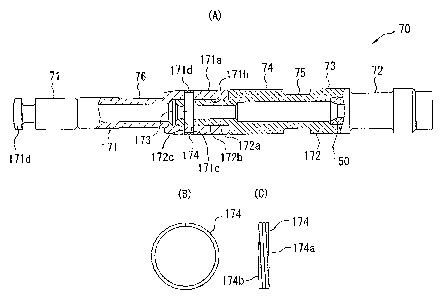
As the valve spool 70 forming the clutch CL described above is an axially
extended
long cylindrical member and high dimensional precision is required for outside
dimensions of the guide land 71 fitted in the guide member 77, the central
land 73
and the left land 74, the valve spool is divided into a first spool member 171
and a
second spool member 172. Referring to Fig.'s 19(a) to (c), the configuration
of the
valve spool 70 and the ring 174 will be described below. The ring 174 may be
slightly narrower in width as compared to the width of the holding groove
171d.
The first spool member 171 is the cylindrical member provided with a fitted
part
171d fitted to the fitting part 62c of the pressure receptor 62 at its left
end provided
with the guide land 71 fitted in the guide member 77 next to the fitted part.
The
guide land 71 is fitted in the guide member 77, functions as a part for
guiding the
axial movement of the valve spool 70, the fitted part functions as a part for
sealing
the variable oil chamber 78a, and its outside dimension is required to be
finished
to have high precision.
In the first spool member 171, the variable oil chamber forming groove 76 is
formed on the right side of the guide land 71 and at its right end, a fitting
concave
portion 171a in which a concentric fitting hole 171b axially extended inward
and
open to the right end side is formed is provided. A first coupling hole 171c
extended in a direction perpendicular to the axis is formed in the fitting
concave
portion 171a and an annular holding groove 171d concave in a circumferential
direction is formed on the periphery of the first coupling hole 171c.
In the meantime, in the second spool member 172, a valve part which is
provided
with the right groove 72, the central land 73, the left groove 75 and the left
land 74,
which executes communication/cutoff control between the inside branched oil
passage 6a and the outside branched oil passages 6b, 6c and which executes
clutch
control is formed. In this valve part, the central land 73 and the left land
74
function as a valve as described above and their outside dimensions are
required
to be finished to have high precision.
At a left end of the second spool member 172, a fitting convex portion 172a
having
a concentric fitting protruded cylindrical face 172b protruded on the axial
left side
CA 02627500 2011-06-14
WH-13322CA - 28 -
SN 2,627,500
is provided. The fitting protruded cylindrical face 172b is formed in
dimensions
fitted into the fitting hole 171b and a second coupling hole 172c is pierced,
the
second coupling hole 172c is matched with the first coupling hole 171c in a
condition fitted into the fitting hole 171b and extended in a direction
perpendicular to the axis.
In the first spool member 171 and the second spool member 172 respectively
configured as described above, a coupling pin 173 is inserted into the first
and
second coupling holes 171c, 172c matched in a condition in which the fitting
convex portion 172a is fitted into the fitting concave portion 171a, the first
and
second spool members are lockably coupled with the coupling pin 173 in the
center to form the valve spool 70. As a high dimensional precision is required
for
only the outside diameter of the guide land 71 in the first spool member 171
and
for only the respective outside diameters of the central land 73 and the left
land 74
in the second spool member 172 respectively by dividing the valve spool 70
into
the first and second spool members 171, 172 as described above, the
manufacture
of time spool members is facilitated and the dimensional precision of the
outside
diameters can be easily enhanced.
As the coupling pin 173 is relatively moderately inserted into the first and
second
coupling holes 171c, 172c, a ring 174 is fitted into the holding groove 171d
to
prevent the coupling pin 173 from falling out. As a result, the ring 174 is
fitted
with the ring covering an opening at a peripheral end of the first coupling
hole
171c, closes both ends of the coupling pin 173, and prevents the coupling pin
from
falling out.
The ring 174 is formed in a coil acquired by bending wire the section of which
is
circular or rectangular in a ring plural times. Therefore, the ring 174 can be
easily
fitted into the holding groove 171d by spreading the diameter of the coil. End
faces 174a, 174b on both sides of the ring 174 are worked to be flat and as
shown in
Fig. 19(C), the lateral width of the ring is equal overall. The lateral width
is set to
be slightly narrower than the width of the holding groove 171d and the ring
174 is
fitted into the holding groove 171d without rattling.
CA 02627500 2008-03-25
-29-
In this embodiment, the ring 174 is formed by bending the wire in the ring
plural
times to be the coil, however, the ring may be also formed by bending thickish
wire in a ring only once. However, in this case, it is desirable that the ends
are
overlapped without clearance in a circumferential direction. An inside face of
the
ring 174 may be also attached to the holding groove 171d with a loose fit
(with
clearance). Hereby, the valve spool 70 can be easily inserted into the spool
hole
6d.
In the hydrostatic continuously variable transmission CVT configured as
described above, a lock-up mechanism 90 is provided, the lock-up mechanism 90
closes the hydraulic closed circuit to be a lock-up condition when
transmission
gear ratio is 1.0, that is, when the input revolution speed of the hydraulic
pump P
and the output revolution speed of the hydraulic motor M are equal. Referring
to Figs. 15 to 17, the lock-up mechanism 90 will be described below. The lock-
up
mechanism 90 is provided with the motor eccentric member 91 slid on the end of
the motor casing 30b as described above. The whole motor eccentric member 91
is formed in a ring and the motor-side cam ring 54 is arranged on its inside
face
91a. A fitting part 91a is formed at an upper end of the motor eccentric
member
91, is fastened to the motor casing 30b by a fitting pin 92, and the motor
eccentric
member 91 is rockably attached to the motor casing 30b with the fitting pin 92
in
the center.
To rock the motor eccentric member 91, a lock-up actuator LA is attached to
the
motor casing 30b with the lock-up actuator located on the downside of the
motor
eccentric member 91. The lock-up actuator LA is configured by a cylinder 96
fixed to the motor casing 30b, a piston 94 slidably arranged in a cylinder
hole of
the cylinder 96, a lid 95 that closes the cylinder hole and is attached to the
cylinder 96 and a spring 97 that energizes the piston 94 toward the lid 95.
The
cylinder hole is divided in two by the piston 94, a lock-up hydraulic fluid
chamber 96a and a lock-up release chamber 96b are formed, and a spring 97 is
arranged in the lock-up release chamber 96b. An end of the piston 94 is
protruded outward from the cylinder 96 and the protruded part 94a is fastened
to a coupling part 91b formed in a lower part of the motor eccentric member 91
via a coupling pin 93.
WH-13322/cs
CA 02627500 2008-03-25
-30-
In the lock-up mechanism 90 configured as described above, when the oil
pressure of the lock-up hydraulic fluid chamber 96a is released, the piston 94
is
moved on the side of the lid 95 by energizing force by the spring 97 arranged
in
the lock-up release chamber 96b. At this time, as shown in Fig. 16, the
coupling
part 91b is touched to an outer end face 96c of the cylinder 96, in this
condition,
the center C2 of the inside face 91a of the motor eccentric member 91 is
eccentric
with the center C1 of the transmission output shaft 6 and the output rotor
(the
motor cylinder 32), and the motor eccentric member 91 is located in a normal
position.
In the meantime, when lock-up hydraulic fluid pressure is supplied to the lock-
up hydraulic fluid chamber 96a, the piston 94 is moved rightward against
energizing force by the spring 97 by the fluid pressure as shown in Fig. 17
and
the protruded part 94a is further protruded. Hereby, the motor eccentric
member 91 is rocked counterclockwise with the fitting pin 95 in the center a
shown in Fig. 17 and as shown in Fig. 17, a contact face 91c formed on the
side of
the motor eccentric member 91 is touched to a contact face 98a of a
positioning
projection 98 integrated with the motor casing 30a. In this condition, the
center
C2 of the inside face 91a of the motor eccentric member 91 is overlapped with
the
center C1 of the transmission output shaft 6 and the output rotor (the motor
cylinder 32) and the motor eccentric member 91 is located in a lock-up
position.
As known from the configuration of the hydraulic motor M and the
configuration of the distributing valve 50 respectively described above, when
the
motor eccentric member 91 is located in the lock-up position, the center of
the
motor-side cam ring 54 arranged on the inside face 91a coincides with the
rotational center of the motor cylinder 32, even if the motor cylinder 32 is
rotated,
the motor-side spool 55 is not reciprocated, and the supply of high-pressure
oil to
the motor plunger 33 is cut off. At this time, the motor plunger communicates
with the oil passage 56 on the low pressure side. As a result, the reduction
of
compression loss and hydraulic fluid leakage in the motor plunger 33, the
reduction of the mechanical power loss of the bearing and others because no
high
pressure is applied to the motor plunger 33 and further, the reduction of
WH-13322/cs
CA 02627500 2008-03-25
-31-
resistance in sliding the pump-side spool 53 are enabled, and power
transmission
efficiency is enhanced.
As known from the above-mentioned description, when lock-up hydraulic fluid
pressure is supplied to the lock-up hydraulic fluid chamber 96a in the lock-up
mechanism 90, the motor eccentric member 91 is rocked and is located in the
lock-up position to be in the lock-up condition. That is, independent of the
gear
ratio of the hydrostatic continuously variable transmission CVT, if only lock-
up
hydraulic fluid pressure is supplied to the lock-up hydraulic fluid chamber
96a,
the lock-up condition can be hydraulically produced. However, as described
above, as lockup should be made when transmission gear ratio is 1.0, lockup is
set so that lock-up hydraulic fluid pressure cannot be supplied unless the
transmission gear ratio is in the vicinity of 1Ø Referring to Figs. 1, 4 and
20, this
configuration will be described below.
Lockup control oil passages 131, 132, 133 for supplying lock-up hydraulic
fluid
pressure to the lock-up hydraulic fluid chamber 96a are formed in the
transmission housing HSG and the motor casing 30 (30a, 30b) as shown in the
drawings. The lockup control oil passage 131 connects with a lockup control
oil
pressure supply control valve not shown, is controlled by the valve, and
lockup
control oil pressure is supplied to the lockup control oil passage. The lockup
control oil passage 133 connects with the lock-up hydraulic fluid chamber 96a
of
the lock-up mechanism 90. Therefore, basically, oil pressure supply control by
the lockup control oil pressure supply control valve is executed and lock-up
operation control can be executed.
However, a branched oil passage 134 branched from the lockup control oil
passage 132 is formed with the branched oil passage open to a concave
supporting cylindrical face 30c formed on the inside face of the motor casing
30
and lock-up hydraulic fluid is exhausted in the casing from the branched oil
passage 134 through an opening 134a. A convex rocking supported cylindrical
face 35b that forms the back side of the motor rocking member 35 that
rotatably
supports the motor swash plate 31 is slid on the supporting cylindrical face
30c
and in a condition that an angle of the swash plate is relatively large as
shown in
WH-13322/cs
CA 02627500 2008-03-25
-32-
Figs. 1 and 4, the opening 134a is open. In the meantime, as shown in Fig. 20,
when the angle of the swash plate is in the vicinity of zero (a swash plate
surface
is in a direction perpendicular to the axis), the rocking supported face 35b
covers
and closes the opening 134a of the branched oil passage 134.
As described above, when the angle of the swash plate is in the vicinity of
zero
which is substantially zero, that is, when transmission gear ration is in the
vicinity of 1.0 which is substantially 1.0, the opening 134a of the branched
oil
passage 134 is closed. Therefore, only in the vicinity of a position of the
swash
plate angle in which the transmission gear ratio is 1.0 and lockup is
required,
lockup control oil pressure can be supplied to the lock-up hydraulic fluid
chamber 96a via the lockup control oil passages 131 to 133. As the opening
134a
of the branched oil passage 134 is open when an angle of the swash plate is
except it, that is, when no lockup is required, lockup control oil pressure is
exhausted in the casing through the branched oil passage 134 even if the
lockup
control oil pressure is supplied to the lockup control oil passage 131 and no
lockup control oil pressure acts on the lock-up hydraulic fluid chamber 96a.
Next, referring to Figs. 12 to 14 and Fig. 18, the configuration of a system
for
supplementing hydraulic fluid in the hydraulic closed circuit will be
described.
As shown in Fig. 18, hydraulic fluid is supplemented by the oil pump OP (see
Fig. 3) and discharged oil from the oil pump OP driven by the engine E is
supplied to an oil passage 160 axially extended in the transmission output
shaft 6
via an oil passage in the transmission housing HSG. The oil passage 160
connects
with an oil passage 161 extended in a radial direction in the transmission
output
shaft 6 and open to the periphery at the end of the oil passage 160. The oil
passage 161 further connects with oil passages 162a, 162b, 162c axially
extended
in the output rotor (the motor cylinder 32, the valve body 51 and the pump
cylinder 22), an orifice 164 communicating with the outside is formed at the
end
of the oil passage 162c, and the inside of the transmission is lubricated by
hydraulic fluid that flows outside from the orifice 164.
A first check valve 170a for supplying supplemented oil to the outside passage
57
and a first relief valve 175a for relieving hydraulic fluid when oil pressure
in the
WH-13322/cs
CA 02627500 2008-03-25
-33-
outside passage 57 exceeds predetermined high pressure are provided in the
pump cylinder 22 as shown in Figs. 12 to 14. Further, a second check valve
170b
for supplying supplemented oil to the inside passage 56 and a second relief
valve
175b for relieving hydraulic fluid when oil pressure in the outside passage 57
exceeds predetermined high pressure respectively having the similar
configuration to the configuration of the above-mentioned valves are also
provided though the two valves are not shown in Figs. 12 to 14.
An oil passage 163a that connects the oil passage 162c and the first check
valve
170a is formed in the pump cylinder 22 as shown in Figs. 12 to 14 and
hydraulic
fluid supplied from the oil pump OP is supplied to the outside oil passage 57
via
the first check valve 170a as supplemented oil if necessary (according to
leakage
from the hydraulic closed circuit). The plural oil passages 162a, 162b, 162c
are
formed, an oil passage 163b that connects an oil passage 162c and a second
check
valve 170b is formed in the pump cylinder 22, and hydraulic fluid supplied
from
the oil pump OP is supplied to the inside oil passage 56 via the second check
valve 170b as supplemented oil if necessary (according to leakage from the
hydraulic closed circuit).
In the meantime, hydraulic fluid relieved from the first relief valve 175a
when oil
pressure in the outside passage 57 exceeds predetermined high pressure set by
energizing means is exhausted in a return oil passage 165a formed in the pump
cylinder 22. The return oil passage 165a communicates with a ring oil passage
166 formed on the periphery of the transmission output shaft 6 in a ring,
fitted to
the pump cylinder 22 and encircled by the pump cylinder. The oil passage 166
communicates with the oil passage 162c via the oil passage 163a and as known
from this, hydraulic fluid relieved from the first relief valve 175a is
exhausted in
an oil passage for supplying supplemented oil supplied from the oil pump OP.
Hydraulic fluid relieved from the second relief valve 175b is also exhausted
in
the oil passage 162c, that is, in a supplemented oil supply oil passage from
the
return oil passage 165b via the ring oil passage 166 and the oil passage 163b
though the passages are not shown.
WH-13322/cs
CA 02627500 2008-03-25
-34-
As described above, as hydraulic fluid relieved from the first and second
relief
valves 175a, 175b is exhausted in the supplemented oil supply oil passage 162c
through the return oil passages 165a, 165b and relieved oil is never returned
to
the hydraulic closed circuit, the rise of oil temperature in the hydraulic
closed
circuit can be inhibited. As oil pressure in the supplemented oil supply oil
passage 162c is stable, hydraulic fluid in the oil passage on the high
pressure side
can be efficiently relieved.
As the supplemented oil supply oil passage is extended from the transmission
output shaft 6 into the output rotor, the first and second relief valves 175a,
175b
and the return oil passages 165a, 165b are arranged in the pump cylinder 22
(the
output rotor) and the return oil passages 165a, 165b connect with the
supplemented oil supply oil passage 162c in the pump cylinder 22, high-
pressure
relief structure is compactly housed in the pump cylinder 22 and can be made
compact such as the return oil passages 165a, 165b can be reduced. The return
oil
passages 165a, 165b connect with the supplemented oil supply oil passages 162c
(and 163a, 163b) via the ring oil passage 166 circumferentially extended in
the
part fitted to the pump cylinder 22 on the outside face of the transmission
output
shaft 6 and oil passages coupling structure in the part is simple.
The embodiment that the continuously variable transmission according to the
invention is adopted in the motorcycle is described above, however, the
invention is not limited to being adopted in a motorcycle and can be adopted
in
various power transmission mechanism such as a four-wheel vehicle, a vehicle
including an automobile and a general purpose machine.
Although various preferred embodiments of the present invention have been
described herein in detail, it will be appreciated by those skilled in the
art, that
variations may be made thereto without departing from the spirit of the
invention or the scope of the appended claims.
WH-13322/cs