Note : Les descriptions sont présentées dans la langue officielle dans laquelle elles ont été soumises.
CA 02628359 2008-04-04
1
SEGMENTAL RETAINING WALL BLOCKS DESIGNED FOR CURVED OR
STRAIGHT ALIGNMENT
INTRODUCTION
The present invention relates to segmental retaining wall blocks of tapered
shape that are configured in such a manner as to prevent infiltration of
backfill
materials such as soil into voids that exist between the backs of the blocks
when
installed.
BACKGROUND OF THE INVENTION
It is of common practice for a landscape architect, contractor or homeowner,
to
design the layout of a proposed segmental retaining wall (SRW) in curved or
snaking alignments. Curving alignments with tight or large radii, give a
natural
organic flow to the retaining wall that may better blend in with the natural
environment when compared to straight lines and hard corners.
Currently, the segmental retaining wall blocks used to achieve curved
alignments have one or both of their sides that are tapered when the blocks
are
viewed in top plan view (i.e., the width of the rear of each block is less
than the
width of the face of the block).
In practise, some manufacturers offer standard blocks with front and rear of
the
same width for the manufacture of straight walls (see Figures 1 a and lb
identified as "prior art"). They also offer tapered blocks for used to give
curved
sections to the walls (see Figures 2a and 2b also identified as "prior art").
Alternatively, other manufacturers offer tapered blocks with rear wings that
can
be knocked off. Where the rear wings are kept, the blocks be used as such to
build a straight wall (see Figures 3a and 3b identified as prior art). When
the rear
wings are knocked off, the constructor may then create a tapered version of
the
CA 02628359 2008-04-04
2
block and used such blocks for curved walls (see Figures 4a and 4b identified
as
"prior art").
As may be appreciated, the taper or angle set into the sidewall(s) of the
blocks
dictate the minimum allowable convex radius the wall will be able to achieve.
For
a block that is tapered on both sides (dual tapered) or tapered on one side
only,
the same equation applies to resolve the minimum allowable radius the blocks
can achieve when abutted immediately against one another in a curve or a
circle. The equation is as follows (see Figure 5).
D = Depth of Block (front to back depth)
Wf = Width of Face of Block
Wr = Width of Rear of Block
R = Minimum allowable radius of blocks
9t = Total Angle from vertical axis of block sidewalls
6t = (Tan-' ((Wf-Wr)/D) (Equation 1)
R = 18( 0 Wf ) (Equation 2)
(PI(9t))
One major flaw exists with the current design of the tapered SRW block.
Because the block is a "precast" unit, the taper is permanently set to the
"minimum" or smallest possible radius. This allows the user to create curves
that
have radii ranging from almost straight to the tightest possible radius.
Although
this does give the user flexibility in creating both large and small radius
curves, it
also creates a problem. When the tapered blocks are set at the highest
possible
radius, no gap exists at the rear of the wall (see Figure 5a identified as
"prior
art"). In other words, the rear wall formed at the back of the wall is solid,
just like
the face. However, when a radius is constructed that is larger than the
minimum,
CA 02628359 2008-04-04
3
which occurs most often, the total rotation or taper of the block is not fully
utilized. That is, a gap is left at the back of the blocks between each unit.
If the
radius is significantly larger than the minimum, this gap can be considerable
(see Figure 5b identified as "prior art"). By experience, such a gapping in
the
back of the wall leads to the three following probiems.
Problem 1- Backfill material migrate into "voids" creating losss of
compaction and strength.
First, placement and compaction of backfill materials into these gaps is
difficult if
not impossible and time consuming for the contractor. In many cases, this
leads
to backfill being placed loosely or not at all in this "wedge" between the
back of
the blocks. Through the forces of gravity and/or water flow, the backfill
material
adjacent to (behind) the back of the blocks may migrate into these voids over
time, creating a loss of compaction and soil density immediately behind the
wall.
The compaction of the backfill materials and subsequent soil density is
critical to
the strength of the backfill materials and the performance of the wall. As
such,
this mechanism may cause a loss of strength in the backfill materials, which
results in an increase in lateral earth pressure behind the wall, which is not
generally accounted for in standard design practices. An increase in the
lateral
earth pressure, or force, being applied to the wall reduces the overall
factors of
safety assumed in design and may impact the structural performance of the
wall.
Problem 2 - Settlement of backfill materials immediately behind wall.
Along with an increase in earth pressure, the movement of the backfill
materials
immediately adjacent to the back of the blocks results in settlement of the
material in this zone. Settlement in the area (immediately behind the blocks)
results in the following potential problems. First, settlement of backfill
behind the
wall may cause the grade behind the wall to move downward, perhaps to an
unacceptable level. Elements such as swales or asphalt paving constructed
immediately behind the top of the wall may deform differentially, or totally,
CA 02628359 2008-04-04
4
beyond what is allowable if settlement is excessive. Second, settlement by
nature produces additional lateral earth pressures as the backfill materials
are
compressed both vertically and displace laterally. Third, when a geogrid
reinforcement material is used to reinforce the backfill zone, settlement
immediately behind the blocks may result in a failure. of the connection of
the
geogrid reinforcement to the block. As the backfill material settles, the
geogrid
reinforcement, which is installed horizontally, is subjected to a downward
dragging force as it extends out from between the blocks and into the backfill
zone. This downward force created by the settling backfill materials, acts to
drag
the geogrid down, over the back edge of the block. In some cases, the square
edge at the back of the block, combined with the presence of small concrete
burs created at this seam during the manufacturing of the block, are enough to
damage or completely sever the geogrid, when it is being pulled down against
it
by the settling backfill materials immediately behind the block. This results
in a
lower or non-existent connection to the block, at which point the structural
integrity of the wall has been compromised.
Problem 3 - Migration of fine materials through the face of the wall.
Natural forces of gravity and water flow acting on the backfill materials may
carry
soil fines into these voids created by the gaps at the back face of the wall.
If
these forces are sufficient, the soil fines may be carried through the voids
and
out to the face of the wall. The staining caused by the soil fines being
deposited
on the face of the wall is often unacceptable to the consumer from an
aesthetic
point of view.
The problems listed above are the result of a tapered block being used in
applications where the radius being constructed is not the minimum radius. As
such, gaps are created at the rear of the wall immediately adjacent to the
backfill
material. The backfill material is then not contained and may migrate into
these
voids or gaps between the blocks, leading to the above issues.
CA 02628359 2008-04-04
SUMMARY OF THE INVENTION
The present invention relates to a segmental retaining wall (SRW) block that
is
unique in that it allows the user to construct inside and outside (concave and
convex) radii with the blocks, while maintaining a full barrier at the rear of
the
block to the infiltration of backfill soils into the facing or through the
facing.
Thanks to its particular configuration, the SRW block according to the
invention
allows straight or curved alignments while directly addressing the issue of
the
creation of large voids in the back of the wall that occurs with existing
tapered
SRW blocks that exist when the blocks are not placed in the minimum convex
alignment. The plan configuration of the SRW block according to the invention
can be applied to any size of block, face shape or orientation. It provides
lateral
shear between the units such as an integral tongue and groove, mechanical
connectors or pins, adhesive, etc. Despite the method of vertically
interlocking
the units (lateral shear between units), these elements would have to take
into
account the ability of the block to curve within certain limits.
More specifically, the SRW block according to the invention solves the above
mentioned problems encountered with prior art in that, thanks to its
configuration, it blocks the migration of backfill materials at the rear of
the wall,
regardless of the size of the radius or curvature being constructed.
This SRW block is tapered to allow the block to turn a radius. It comprises a
protruding wing or tab on one side, and the congruent receiving "bay" area on
the other.
When several of these blocks are placed adjacent to each other in a straight
alignment, the wing protrudes or overlaps into the bay area a certain distance
required to create a barrier against the migration of fines when the block is
placed in a concave alignment. The front edge of the wing and the front edge
of
the receptacle bay are designed as congruent arcs, the front edge of the wing
CA 02628359 2008-04-04
6
being set to a radius just slightly larger than the radius of the front edge
of the
bay area to allow for construction and manufacturing tolerance. As the blocks
are rotated to achieve a curve, the wing moves further into the bay area,
thereby
creating an even greater overlap and barrier to the migration of fines. When
the
blocks are fully rotated to the minimum allowable radius, the wing fills the
bay
area.
So, the invention as claimed hereinafter is essentially directed to a
segmented
retaining wall (SRW) block having a front wall, a rear wall and two opposite
side
walls, wherein:
one of said side walls is rearwardly tapered so as to allow said block to
turn a radius when placed in adjacent position with respect to another similar
SRW block,
said rear wall is provided with a protruding wing that projects laterally
away from the tapered side wall;
said rear wall is also provided with a bay that extends inwardly in the side
wall that is opposite to the tapered side wall;
said wing and bay have front edges designed as congruent arcs; and
said wing is sized and shaped so as to protrude into the bay of an
adjacent similar SRW block to create a barrier wherein said adjacent SRW
blocks are in straight, convex or concave alignment.
The invention and its advantages will be better understood upon reading the
following non-restrictive description of a preferred embodiment thereof, made
with reference to the accompanying drawings.
BRIEF DESCRIPTION OF THE DRAWINGS
Figure 1 a is a top plan view of a standard SRW block;
Figure lb is a top plan view of a wall made of several SRW blocks as
shown in Figure 1 a;
Figure 2a is a top plan view of existing tapered SRW block;
CA 02628359 2008-04-04
7
Figure 2b is a top plan view of a wall made of several tapered SRW
blocks as shown in Figure 1 b;
Figure 3a is a top plan view of an existing SRW block with rear wings that
can be knocked off;
Figure 3b is a top plan view of a wall made of SRW blocks as shown in
Figure 3a, with their rear wings still present;
Figure 4b is a top plan view of a wall made of SRW blocks as shown in
Figure 3b, with their rear wings knocked off;
Figure 5a is a top plan view similar to Figure 2b, with no gaps between
the rear sides of the blocks where the backfill material may migrate;
Figure 5b is a top plan view similar to Figure 5a but with the blocks placed
in radius larger than the minimum and backfill material in between;
Figure 6 is a top plan view of a SRW block according to a preferred
embodiment of the invention;
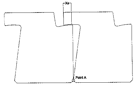
Figure 7 is a top plan view of two SRW blocks as shown in Figure 5
adjacent to each other, in a straight alignment;
Figure 8 is a top plan view of two SRW blocks as shown in Figure 5 in a
convex alignment;
Figure 9 is a top plan view of two SRW blocks as shown in Figure 5 in a
concave alignment; and
Figure 10 is a view similar to the one of Figure 7, but showing an
enlarged view of the manufacturing and constructions tolerated.
In these drawings and the following description, the following
abbreviations or symbols correspond to the following:
Wface = Width of face of block
Point A Rotation point of block on Side A
Side A Left side of the block
Side B Right side of the block
A= Taper Angle on Side A of block
8= Taper Angle on Side of bay B
Arc A = Arc length of protruding wing on Side A
CA 02628359 2008-04-04
8
Arc B = Arc length at bottom of bay area on Side B
Xs = Overlap length of arc A over arc B when blocks set in straight alignment
Xconvex = Overlap length of arc A over arc B when blocks set in minimum
convex curve (maximum overlap possible)
Xconcave = Overlap length of arc A over arc B when blocks set in minimum
concave curve (minimum overlap possible)
D = Front to back depth of block
Wd = Wing depth
Bd = Bay depth
t = Manufacturing and construction tolerances
Omin = Minimum overlap of wing into bay area in minimum concave alignment
(worst case) to prevent infiltration of fines.
DETAILED DESCRIPTION OF THE INVENTION
The SRW block according to the preferred embodiment of the invention as
shown in Figure 6 is rectangular or square block having a left side (Side A)
which differ from its right side (side B). The left side (Side A) of the block
has an
angle or tapered sidewall (angle = 9 from the vertical). This angle represents
the
desired minimum convex radius the user would want to achieve based on
Equations I and 2 shown above.
In the illustrated preferred embodiment, Side A is tapered and Side B is
straight.
However, Side A and Side B could also split, provided that the total taper
angle
(6) remains between them.
In the illustrated preferred embodiment, the Side B has a straight sidewall
for
greater ease of explanation. From a manufacturing point of view, it is also
desirable to have a flat or straight sidewall on at least one side of the
block to
move and package the material. The tapered Side A allows the block to turn a
convex radius in the traditional way previously described. However, rather
than
continuing the tapered sidewall right to the rear of the block, a wing
protrudes
CA 02628359 2008-04-04
9
out from the side of the block at the rear. The depth of the wing (Wd) is set
to
ensure that the wing piece be adequately strong to prevent breaking off during
construction and shipping. The lower edge of the wing identified as arc A in
Figure 5, is formed as an arc. When two blocks are placed side by side, point
A
of one block is adjacent to point B of the other. As the block rotates its
point A,
the radius of the arc A identified in Figure 5 as the wing radius (Rw) is as
follow:
Rw = D - Wd (Equation 3)
Indeed, when the center of rotation is point A, the radius is the block depth
(D),
minus the depth of the wing (Wd).
The wing (arc A) extends out past the imaginary vertical edge of Side A(viz.
the
side which is not tapered) at a distance noted as Xs. This distance Xs is a
function of the required minimum overlap in the worst case scenario, which is,
when the blocks are rotated outwards to form a concave curve and the overlap
is the minimum. This will be described in more details hereinafter.
The straight sidewall (Side B) is designed on a congruent bay area in the top
right corner of the block that accepts the wing of side A. The depth of the
bay
area (Bd) is slightly larger than the depth of the wing (Wd) to allow
construction
and manufacturing tolerances.
Therefore, the value Bd - Wd is illustrative of the construction and
manufacturing tolerances.
The lower edge of the bay area on Side B (arc B) is designed as a congruent
arc
with arc A. The radius of the arc B is just slightly less than of arc A to
allow
movement of the wing into the bay area, given to manufacturing and
construction tolerances. Therefore, the radius of arc B, hereinafter called
bay
radius Rb, is equal to the wing radius (Rw) less the Manufacturing and
Construction Tolerances (t).
Rb = Rw - t (Equation 4)
CA 02628359 2008-04-04
The left sidewall of the bay area is designed to align (S) with the left side
wall of
the wing when the blocks are placed at the minimum convex rotation and the
wing completely fills the bay area. The left sidewall of the wing is vertical
when
the block is placed in a straight alignment, so as it rotates into a convex
curve,
the vertical sidewall rotates about point A and is now angled. The left
sidewall of
the bay area therefore must be set to the maximum angle the block is able to
rotate, which is 9.
Therefore:
10 8 = S (Equation 5)
The invention is designed to ensure that when the blocks are placed in a
straight
alignment, convex curve, or concave curve, an overlap of the wing and the bay
area exists that is sufficient to prevent the migration of backfill materials
into the
back of the blocks. Figure 7 shows two blocks placed adjacent to each other in
a
straight alignment. As can be seen, overlap is Xs. Figure 8 shows two blocks
placed adjacent to each other in a convex alignment. This minimum convex
radius is the best case scenario for providing a barrier to the infiltration
of backfill
materials. Figure 9 shows two blocks placed adjacent to each other in a
concave
alignment. This minimum concave radius is the worst case scenario for
providing a barrier to the infiltration of the backfill materials.
The distance Xs which is the one of overlap in a straight alignment (see
Figure
7) is determined by what the minimum offset can be in the worst case scenario
which is the distance Xconcave shown in Figure 9.
Therefore, the protrusion of the wing beyond the imaginary vertical sidewall
for
Side A is determined as a function of the minimum radius that is required to
be
achieved by the block and the minimum overlap in the concave alignment.
CA 02628359 2008-04-04
11
The total arc length of the arc A is therefore a function of the overlap in a
minimum convex position plus the overlap in the minimum concave position plus
the minimum overlap in the concave position. The equation for the length of an
arc is as follows (all angles being expressed in degrees):
Arc length (arc A) =(0 (PI) Rw )/ 90 + Omin. (Equation 6) and
Arc length (arc B) = arc A + t (Equation 7)
Xs which is the portion of arc A that extends beyond the imaginary vertical
line
along the sidewall A can then be expressed by the following equation
Xs =(0 (PI) Rw) / 180 + Omin. (Equation 8)
As may now be better understood, the arcs A and B formed at the bottom of the
wing and bay area serve two purposes. First, they allow these elements to
rotate
about point A while maintaining an exact distance apart (depending on the
manufacturing and construction tolerance) as they follow an arc of consistent
radius Rw (see Figure 10). Secondly, the nature of the arc shape automatically
creates an "uphill" configuration between the wing and the bay. In other
words, if
soil materials are being conveyed, either through gravity, water or compaction
forces into the bay area, they will encounter the bottom of the bay area and
will
not be able to continue through the small space between the wing and the bay
(left for construction and manufacturing tolerances) due to the fact that the
direction of soil materials would have to be forced upward, against the
direction
of the applied conveyor forces. This "S" shape creates a natural dam to the
movement of material by its geometric configuration.
So, the configuration of segmental retaining wall blocks according to the
invention allows them to be set in a straight, concave, or convex alignment,
while maintaining a mechanical barrier at the rear to the infiltration of
backfill
soils.