Sélection de la langue

Search

Sommaire du brevet 2629902 

Énoncé de désistement de responsabilité concernant l'information provenant de tiers

Une partie des informations de ce site Web a été fournie par des sources externes. Le gouvernement du Canada n'assume aucune responsabilité concernant la précision, l'actualité ou la fiabilité des informations fournies par les sources externes. Les utilisateurs qui désirent employer cette information devraient consulter directement la source des informations. Le contenu fourni par les sources externes n'est pas assujetti aux exigences sur les langues officielles, la protection des renseignements personnels et l'accessibilité.

Disponibilité de l'Abrégé et des Revendications

L'apparition de différences dans le texte et l'image des Revendications et de l'Abrégé dépend du moment auquel le document est publié. Les textes des Revendications et de l'Abrégé sont affichés :

  • lorsque la demande peut être examinée par le public;
  • lorsque le brevet est émis (délivrance).
(12) Demande de brevet: (11) CA 2629902
(54) Titre français: DETECTION ET LOCALISATION DE FISSURES DANS DES CAPTEURS DISTRIBUES BRILLOUIN DE FIBRE
(54) Titre anglais: DETECTION AND LOCATION OF BREAKS IN DISTRIBUTED BRILLOUIN FIBER SENSORS
Statut: Réputée abandonnée et au-delà du délai pour le rétablissement - en attente de la réponse à l’avis de communication rejetée
Données bibliographiques
(51) Classification internationale des brevets (CIB):
  • G01M 11/00 (2006.01)
  • G01K 15/00 (2006.01)
  • G01L 25/00 (2006.01)
(72) Inventeurs :
  • SEZERMAN, OMUR M. (Canada)
  • YOULE, GORDON DAVID (Canada)
(73) Titulaires :
  • OZ OPTICS LTD.
(71) Demandeurs :
  • OZ OPTICS LTD. (Canada)
(74) Agent: MACRAE & CO.
(74) Co-agent:
(45) Délivré:
(22) Date de dépôt: 2008-04-25
(41) Mise à la disponibilité du public: 2008-10-26
Licence disponible: S.O.
Cédé au domaine public: S.O.
(25) Langue des documents déposés: Anglais

Traité de coopération en matière de brevets (PCT): Non

(30) Données de priorité de la demande:
Numéro de la demande Pays / territoire Date
60/907,993 (Etats-Unis d'Amérique) 2007-04-26

Abrégés

Abrégé anglais


An apparatus for an optical time domain analyzer is provided. The apparatus
has a
pulsed laser source and a continuous wave (CW) laser source. The apparatus
also has a
computer readable memory for detection of a reflected pulse of an outgoing
pulse from
the pulsed laser source, the reflected pulse being reflected from a break in
the fiber or an
unterminated end of the fiber. In another embodiment, a computer program
product
having memory with computer readable code embodied therein is provided for
determining a distance to a break or fiber end in an optical fiber. The
computer program
has means for detecting an outgoing pulse from a pulsed laser source in an
optical time
domain analyzer, means for detecting a reflected pulse and means for
determining the
timing of the reflected pulse relative to the outgoing pulse.

Revendications

Note : Les revendications sont présentées dans la langue officielle dans laquelle elles ont été soumises.


What is claimed is:
1. An apparatus for an optical time domain analyzer, comprising:
a pulsed laser source;
a continuous wave (CW) laser source;
a beam splitter for diverting the light from the CW laser source to the
detector;
a detector for receiving light from the beam splitter;
a control system for controlling the CW laser source and pulsed laser
source; and
a computer readable memory having recorded thereon statements and
instructions for execution by a computer to detect a reflected pulse of an
outgoing pulse from the pulsed laser source, the reflected pulse being
reflected
from a break in the fiber or an unterminated end of the fiber.
2. The apparatus of claim 1 wherein the computer readable memory has
statements and instructions recorded thereon to determine the timing of the
reflected pulse.
3. The apparatus of claim 2 wherein the timing of the reflected pulse is
relative
to the outgoing pulse.
4. The apparatus of claim 3 wherein the timing information of the reflected
pulse
is converted into a measurement of distance to the break or fiber end.
5. The apparatus of any one of claims 1 to 4 wherein the control system is
also
for amplifying the output of the detector, digitizing the output of the
detector,
processing the digitized signal, and communicating with an operator or host
computer.
6. A computer program product, comprising:
a memory having computer readable code embodied therein, for execution
6

by a CPU, for determining a distance to a break or fiber end in an optical
fiber, said code comprising:
first detection code means for detecting an outgoing pulse from a pulsed
laser source in an optical time domain analyzer;
second detection code means for detecting a reflected pulse of the
outgoing pulse from a break in the fiber; and
determination code means for determining the timing of the reflected pulse
relative to the outgoing pulse.
7. The computer program product of claim 6 further comprising:
conversion code means for converting the timing into a measurement of
distance to the break or fiber end.
7

Description

Note : Les descriptions sont présentées dans la langue officielle dans laquelle elles ont été soumises.

CA 02629902 2008-04-25
DETECTION AND LOCATION OF BREAKS IN
DISTRIBUTED BRILLOUIN FIBER SENSORS
TECHNICAL FIELD
This invention relates to the detection of breaks and locating their positions
in the
optical fibers that are used with Brillouin Optical Time Domain Analyzers
(BOTDA).
BACKGROUND INFORMATION
In recent years, Brillouin scattering has been used as a means of detecting
strain
applied to optical fibers. By firmly securing such optical fibers to a
structure (such as a
pipeline, dam, or bridge, for example), some of the strain in the structure
will be passed
on to the attached fiber, which can then be monitored to determine the
magnitude and
location of the strain. Temperature can also be monitored, and under certain
conditions,
both temperature and strain can be monitored simultaneously.
Brillouin sensors can be used for the detection of corrosion in terms of the
strain
change on structural surface due to the corrosion of steel induced deformation
on the
concrete column in large structures. Brillouin fiber optic sensors excel at
long distance
and large area coverage, such as any application with total lengths in excess
of 10 meters.
Distributed Brillouin sensors can be used for much broader coverage and can
locate fault
points not known prior to serisor installation.
Several examples of systems that use Brillouin sensors can be found in the
art. One
sample system is discussed in U.S. Patent No. 6,910,803, which relates to oil
field
applications. This patent teaches the use of fiber optics to sense temperature
only.
Brillouin scattering is employed and photodiodes and frequency determination
are used.
Another example of a system that uses a Brillouin sensor is U.S. Patent No.
6,813,403, in
which large structures are monitored using Brillouin spectrum analysis. A
Brillouin
1

CA 02629902 2008-04-25
scattering sensor is used with two frequency tunable lasers at 1320 nm for
strain,
displacement and temperature determination based on typical measurements.
As another example, U.S. Patent No. 6, 555,807 teaches an apparatus for
sensing strain in
a hydrocarbon well. The apparatus uses a DFB laser split into two signals. A
returned
Brillouin signal is mixed with a reference signal and sent to an analyzer,
where the
Brillouin frequency shift can be detected.
Brillouin Optical Time Domain Analyzers (BOTDA) are a specifrc type of
Brillouin
sensor that uses two laser beams traveling in opposite directions through the
sensing
fiber. One of the beams is a continuous wave (CW) signal, meaning that its
output power
level is constant. The other laser must be pulsed, or used with a modulator.
to create a
brief pulse of light. The pulsed laser beam induces acoustic phonons within
the fiber,
which in turn interacts with the CW laser beam. This interaction modifies the
power in
the CW beam, either increasing or decreasing the power in this beam, as a
function of
location and intensity of applied strain and temperature. When the modified CW
signal
reaches the end of the fiber (close to pulsed laser), it can be split from the
optical fiber
and monitored. Based on the fluctuations of the beam relative to the output of
the pulsed
laser, the amplitude of the strain (or temperature) can be determined, as a
function of
position within the sensing fiber.
The problem with a BOTDA. is that the two laser beams must enter the fiber
from
opposite ends. If the fiber breaks, as may happen when sensing large strains,
further
strain and temperature readings are impossible, as Brillouin sensors rely on
the
interactions between the two beams and their surroundings. With only a single
beam,
detection of Brillouin scattering cannot take place.
When a fiber in a Brillouin distributed sensor system is broken, the location
of the break
must be determined if the fiber is to be repaired. This would normally be done
by
connecting a separate optical time domain reflectometer (OTDR) to the sensing
fiber. An
OTI)R works by sending a pulse of light into a fiber, and measuring the time
it takes for
2

CA 02629902 2008-04-25
the pulse to travel to the break and be reflected back to the OTDR. The time
of travel is
directly related to the distance to the break.
SUMMARY
The present device removes the requirement for a separate OTDR by taking
advantage of
the capability which normally exists within an OTDA, and applying it in a
manner which
is different from that required by a conventional OTDA.
In one aspect, an apparatus for an optical time domain analyzer is provided,
comprising a
pulsed laser source, a continuous wave (CW) laser source, a beam splitter for
diverting
the light from the CW laser source to the detector and a detector for
receiving light from
the beam splitter. A control system controls the CW laser source and pulsed
laser source.
The apparatus also has a computer readable memory having recorded thereon
statements
and instructions for execution by a computer to detect a reflected pulse of an
outgoing
pulse from the pulsed laser source, the reflected pulse being reflected from a
break in the
fiber or an unterminated encl of the fiber.
In a further aspect, the computer readable memory of the apparatus also has
statements
and instructions for determining the timing of the reflected pulse, in
particular with
relativity to the outgoing pulse. The timing information of the reflected
pulse can then be
converted into a measurement of distance to the break or fiber end.
In another aspect, a computer program product is provided comprising a memory
having
computer readable code embodied therein, for execution by a CPU, for
determining a
distance to a break or fiber end in an optical fiber. The code comprises first
detection
code means for detecting an outgoing pulse from a pulsed laser source in an
optical time
domain analyzer, second detection code means for detecting a reflected pulse
of the
outgoing pulse from a break in the fiber and determination code means for
determining
the timing of the reflected pulse relative to the outgoing pulse.

CA 02629902 2008-04-25
In a further aspect, the computer program product also has conversion code
means for
converting the timing into a measurenient of distance to the break or fiber
end.
BRIEF DESCRIPTION OF THE DRAWINGS
The following description will be better understood with reference to the
drawings in
which:
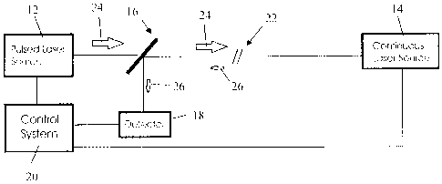
Figure 1 shows a block diagram of a typical configuration of a BOTDA in its
normal,
operating state;
Figure 2 shows a block diagram of a BOTDA system detecting a break in the
fiber; and
Figure 3 shows a typical sigrial received by the detector, when the fiber is
broken or
unterminated.
DETAILED DESCRIPTION OF THE PREFERRED EMBODIMENTS
Figure 1 shows a typical configuration for a BOTDA 10 in its normal, operating
state.
The pulsed laser source 12 may consist of a pulsed laser or a continuous laser
followed
by a device to modulate the laser beam. A second, continuous laser beam
propagates in a
direction opposite to the pulsed beam and is emitted by a continuous laser
source 14.
A beam splitter 16 sends the light from the continuous laser source 14 to a
detector 18
located close to the launch point of the pulsed beam, i.e. close to the pulsed
laser source
12. The light that reaches the detector 18 is primarily from the continuous
laser source
14, with a slight amplitude fluctuation caused by the interaction of the two
laser beams
with the fiber. The control system 20 controls the CW laser source and pulsed
laser
source, amplifies the output of the detector, digitizes the output of the
detector, processes
the digitized signal, and communicates with an operator or host computer.
Figure 2 shows the setup of Figure 1 with a break 22 in the fiber. Light from
the
continuous laser source 14 does not propagate beyond the break 22. Outgoing
light 24
from the pulsed laser source 12 is reflected by the break 22 back towards the
detector 18,
4

CA 02629902 2008-04-25
as shown by the arrow representing the reflected light 26.
During normal operation, the pulsed beam interacts with the fiber and the
continuous
wave (CW) beam, causing fluctuations in the CW beam amplitude that vary as a
function
of the stimulated Brillouin scattering (SBS). The detector 18 and associated
circuitry
measure the amplitude of variations in the CW beam.
If the fiber is broken, the coritinuous beam will not substantially propagate
beyond the
break 22. Light from the pulsed laser source 12 will be reflected at the break
22 in the
fiber back to the detector 18. This reflected light 26 can be detected as a
pulse of light,
witll a waveform similar to the incident pulse, but delayed by the time of
travel to and
from the break. By measuring the time delay of the reflected pulse relative to
the original
pulse, the distance to the break is determined. Figure 3 shows a typical
signal received
by the detector 18, when the fiber is broken or unterminated. The reflected
pulse is
clearly visible in Figure 3, with the time delay between the outgoing and
reflected pulses
being directly proportional to the distance to the point of reflection.
Since both the detector circuitry and the circuitry for generating the laser
pulse already
exist in the BOTDA, additional circuitry is not required. Detecting the
reflected pulse
from the break in the fiber then becomes a matter of signal processing, which
can be
implemented in software, without the need for additional or specialized
hardware. Thus,
a separate OTDR is not required and time and expense are saved since the
distance to the
break in the fiber can be determined directly with any pulse from the pulsed
laser source
after the break occurs.

Dessin représentatif
Une figure unique qui représente un dessin illustrant l'invention.
États administratifs

2024-08-01 : Dans le cadre de la transition vers les Brevets de nouvelle génération (BNG), la base de données sur les brevets canadiens (BDBC) contient désormais un Historique d'événement plus détaillé, qui reproduit le Journal des événements de notre nouvelle solution interne.

Veuillez noter que les événements débutant par « Inactive : » se réfèrent à des événements qui ne sont plus utilisés dans notre nouvelle solution interne.

Pour une meilleure compréhension de l'état de la demande ou brevet qui figure sur cette page, la rubrique Mise en garde , et les descriptions de Brevet , Historique d'événement , Taxes périodiques et Historique des paiements devraient être consultées.

Historique d'événement

Description Date
Demande non rétablie avant l'échéance 2012-04-25
Le délai pour l'annulation est expiré 2012-04-25
Réputée abandonnée - omission de répondre à un avis sur les taxes pour le maintien en état 2011-04-26
Demande publiée (accessible au public) 2008-10-26
Inactive : Page couverture publiée 2008-10-26
Inactive : CIB attribuée 2008-09-30
Inactive : CIB en 1re position 2008-09-30
Inactive : Certificat de dépôt - Sans RE (Anglais) 2008-06-16
Exigences relatives à une correction d'un inventeur - jugée conforme 2008-06-16
Demande reçue - nationale ordinaire 2008-06-06
Exigences de dépôt - jugé conforme 2008-06-06
Inactive : Certificat de dépôt - Sans RE (Anglais) 2008-06-06

Historique d'abandonnement

Date d'abandonnement Raison Date de rétablissement
2011-04-26

Taxes périodiques

Le dernier paiement a été reçu le 2010-01-19

Avis : Si le paiement en totalité n'a pas été reçu au plus tard à la date indiquée, une taxe supplémentaire peut être imposée, soit une des taxes suivantes :

  • taxe de rétablissement ;
  • taxe pour paiement en souffrance ; ou
  • taxe additionnelle pour le renversement d'une péremption réputée.

Veuillez vous référer à la page web des taxes sur les brevets de l'OPIC pour voir tous les montants actuels des taxes.

Historique des taxes

Type de taxes Anniversaire Échéance Date payée
Taxe pour le dépôt - générale 2008-04-25
TM (demande, 2e anniv.) - générale 02 2010-04-26 2010-01-19
Titulaires au dossier

Les titulaires actuels et antérieures au dossier sont affichés en ordre alphabétique.

Titulaires actuels au dossier
OZ OPTICS LTD.
Titulaires antérieures au dossier
GORDON DAVID YOULE
OMUR M. SEZERMAN
Les propriétaires antérieurs qui ne figurent pas dans la liste des « Propriétaires au dossier » apparaîtront dans d'autres documents au dossier.
Documents

Pour visionner les fichiers sélectionnés, entrer le code reCAPTCHA :


Pour visualiser une image, cliquer sur un lien dans la colonne description du document. Pour télécharger l'image (les images), cliquer l'une ou plusieurs cases à cocher dans la première colonne et ensuite cliquer sur le bouton "Télécharger sélection en format PDF (archive Zip)" ou le bouton "Télécharger sélection (en un fichier PDF fusionné)".

Liste des documents de brevet publiés et non publiés sur la BDBC .

Si vous avez des difficultés à accéder au contenu, veuillez communiquer avec le Centre de services à la clientèle au 1-866-997-1936, ou envoyer un courriel au Centre de service à la clientèle de l'OPIC.


Description du
Document 
Date
(aaaa-mm-jj) 
Nombre de pages   Taille de l'image (Ko) 
Description 2008-04-25 5 212
Revendications 2008-04-25 2 46
Abrégé 2008-04-25 1 20
Dessins 2008-04-25 2 20
Dessin représentatif 2008-10-02 1 7
Page couverture 2008-10-16 1 41
Certificat de dépôt (anglais) 2008-06-16 1 157
Certificat de dépôt (anglais) 2008-06-06 1 157
Rappel de taxe de maintien due 2009-12-30 1 112
Courtoisie - Lettre d'abandon (taxe de maintien en état) 2011-06-21 1 173