Note : Les descriptions sont présentées dans la langue officielle dans laquelle elles ont été soumises.
CA 02632001 2008-05-29
WO 2007/062465 PCT/AU2006/001808
1
TRAY POSITION INDICATOR EXTENDING DOWN IN FRONT OF
THE DRIVER WHEN THE TRAY IS IN RAISED POSITION
Field of the Invention
The invention relates to dump haul trucks, and in particular, to a tray
position
indicator for rear-dump.haul trucks which provides a means of indicating and
alerting
a driver of the position of a tray of a rear-dump haul truck to prevent the
driver from
driving away without first lowering the tray.
Whilst the invention may also be applied to other trucks which may have a tray
or
carriage that moves from a lowered to a raised position, for convenience sake
it shall
be described herein in terms of rear-dump haul trucks.
Background to the Invention
Rear-dump haul trucks are commonly used in the mining industry to transport
coal or
other goods around a mine site. These trucks are provided with trays which are
raised in order to dump a load that the truck is carrying in a predetermined
spot. The
problem is that once the load has been dumped, occasionally the driver may
drive
away without remembering to first lower the tray. Such an instance can be
hazardous
as there is a potential for the raised tray of the truck to collide with an
overpass or
power lines or some other obstacle.
In order to overcome this problem, various electronic indicators have been
developed
which are adapted to be installed within the cabin of the truck and indicate
to the
driver that the tray is still in a raised position. These devices usually
comprise a
flashing light, or a speaker for a siren, to be installed within the cabin of
the truck to
attract the driver's attention before they drive away without first lowering
the tray. The
disadvantage of the prior art is that the devices are electronic and can
easily fail due
to their reliance on a power'source for operation. In addition, if the- bulb
of the light is
blown, or the siren sound fails to sound, the devices will fail to alert the
driver of the
tray's position. The prior art fails to provide a mechanical means of
indicating and -
alerting the driver of the position of a tray provided on a rear-dump haul
truck.
Accordingly, it is an object of the present invention to overcome or
substantially
ameliorate the disadvantages of the prior art by providing a tray position
indicator for
CA 02632001 2008-05-29
WO 2007/062465 PCT/AU2006/001808
.2
rear-dump haul trucks which provides a mechanical means of indicating and
alerting
a driver of the position of a tray of a rear-dump haul truck to reduce the
likelihood of a
driver driving away without first lowering the tray.
Summary of the Invention
The present invention provides a tray position indicator including;
at least one elongated member;
at least bracket member; and
an indication means whereby the tray position indicator provides a mechanical
means of indicating and alerting a driver of the position of a tray of a rear-
dump haul
truck to reduce the likelihood of a driver driving away without first lowering
the tray.
A first elongated member is preferably adapted to form the body portion for
the tray
position indicator. The elongated member is preferably adapted to be
positioned
lengthwise/vertically across the top of the truck so that it extends from the
front of the
rear-dump haul truck to the rear of the rear-dump haul truck.
The indication means is preferably in the form of a downwardly extending
member
that is adapted to extend down in front of the driver's view when the tray is
in a raised
position. The downwardly extending member preferably has provided a connecting
portion and a plate member. The connecting portion is preferably adapted to
enable
the indication means to be connected to the second elongated member. The
connecting portion preferably has provided an aperture which is adapted to
receive a
front end of the second elongated member therein. The plate member is
preferably
adapted to provide a signage means and/or allow a sign to be connected thereto
via
a suitable securing means.
The bracket member which is preferably adapted to connect the elongated member
to the truck and provide a pivot point for the tray position indicator. The
bracket
member preferably has at least one connecting portion. A first connecting
portion of
the bracket member is preferably adapted to provide a connection means for the
bracket member to the truck. The first connecting portion is preferably in the
form a
cylindrical or annular portion having a central aperture which is adapted to
receive an
attachment means therethrough. A second connecting portion is preferably
adapted'
to provide a connections means for the bracket member to the elongated member.
The second connecting portion is in the form of a clamp like member having two
CA 02632001 2008-05-29
WO 2007/062465 PCT/AU2006/001808
3
portions which are adapted to be connected together, via at least one suitable
fastening means such as a screw or bolt or the like, to securely hold the
elongated
member.
In an alternate embodiment, the tray position indicator preferably comprises
two
elongated members which are adapted to be connected to the rear of the truck
via
bracket members having a single indication 'means connected between the two
elongated members.
In order that the invention may be more readily understood we will describe by
way of
non-limiting example of a specific embodiment thereof.
Brief Description of the Drawing Figures
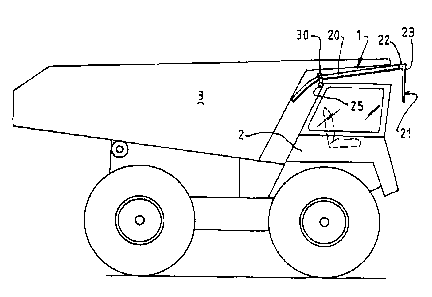
Figure. 1 shows the tray position indicator according to a preferred
embodiment
of the invention.
Figure 2 shows the tray position indicator in a raised position, when the tray
of
the truck is 'lowered, according to a preferred embodiment of the
invention.
Figure 3 shows' an example of the attachment of the tray position indicator to
the rear of the truck according to an embodiment of the invention.
Figure 4 shows an example of the bracket member of the tray position indicator
according to a preferred embodiment of the invention.
Description of a Preferred Embodiment of the Invention
Figures 1 to 4 show the tray position indicator according to a preferred
embodiment
of the invention.
In this preferred embodiment, the invention provides a tray position indicator
1 for
rear-dump haul trucks which provides a mechanical means of indicating and
alerting
a driver of the position of a tray of a rear-dump haul truck to reduce the
likelihood of a
driver driving away without first lowering the tray. The tray position
indicator 1 is
preferably made of a polyethylene (poly) material, or any other suitable
material
CA 02632001 2008-05-29
WO 2007/062465 PCT/AU2006/001808
4
which is strong, durable and flexible and meets the requirements of the
invention. It is
envisaged that the colour, shape and dimensions of the tray position indicator
1 may
also be varied so that the tray position indicator I may be adapted for use
with
different sized and different model rear-dump haul trucks and/or other
applications.
The tray position indicator 1 has provided at least one elongated member. In a
preferred embodiment, the tray position indicator 1 preferably has provided a
single
elongated member 20 which is adapted to form the body portion for the tray
position
indicator 1. The elongated member 20 preferably has a cylindrical rod-like
shape.
However, it is envisaged that the elongated member 20 could also have a
rectangular rod-like shape or any other suitable shape or form. The elongated
member 20 is preferably hollow along the entire length of the elongated member
20:
The elongated member 20 is preferably adapted to have a reinforcement means
provided within the interior of the member 20 to provide additional strength
and/or
flexibility to the elongated member 20. However, in an alternate embodiment,
it is
envisaged that the elongated member 20 could be solid. The combination of the
material and reinforcement should be such that the elongated member 20 is both
flexible and strong to withstand the weight of a tray 3 placed thereon for a
long period
of time, whilst also having memory to return to its initial straightened form
as soon as
the tray 3 is raised so that gravity will force the front of the tray position
indicator 1 in
a downward direction.
The elongated member 20 is adapted to be positioned lengthwise/vertically
across
the top of the truck 2 so that it extends from the front of the rear-dump haul
truck 2 to
the rear of the rear-dump haul truck 2. The length of the elongated member 20
is
preferably determined by the size of the truck 2 and tray 3 which it must
pivot about
to operate. The elongated member 20 is preferably connected to the truck 2 via
a
bracket member 30. The bracket member 30 is preferably positioned at a
predetermined point along the back half of the elongated member 20 to provide
a
connection that is off-centre which in turn will provide the tray position
i.ndicator 1 with
a see-saw mechanism whereby the weight of the tray position indicator I will
be
biased on the front side of the device 1.
Provided at the front end of the elongated member 20 is an indication means 21
which is adapted to indicate the position of the tray 3 to a driver. The
indication
means 21 is preferably in the form of a downwardly extending member that is
adapted to extend down in front of the driver's view when the tray 3 is in a
raised
CA 02632001 2008-05-29
WO 2007/062465 PCT/AU2006/001808
position. The downwardly extending member preferably has provided a connecting
portion 22 and a plate member 23. The connecting portion 22 is preferably
adapted
to enable the indication means 21 to be connected to the second elongated
member
20. The connecting portion 22 preferably has provided an aperture 24 which is
adapted to receive a front end of the second elongated member 20 therein. The
connecting portion 22 is preferably attached to the second elongated member 20
via
a suitable securing means (not shown) such.as a screw or bolt or the like. It
is
envisaged that the connecting portion 22 of the indication means 21 could also
be
integrally formed with the elongated member 20 and/or secured thereto via
welding
or any other suitable means. The plate member 23 is preferably integrally
formed
with, or welded to,'the connecting portion 22 and is adapted to provide a
signage
means and/or.allow a sign to be connected thereto via a suitable securing
means
such as a screw, rivet or bolt or the like. It is envisaged that the sign may
vary
depending on the particular machine or the purpose of the sign however, it is
preferred that the sign may be coloured or have provided some other indicator
which
promotes safety and is adapted to make the sign noticeable and bring a
driver's
attention to the sign when it is in a lowered position indicating that the
tray 3 position
of the haul truck 2 is still raised.
The tray position indicator 1 has provided a bracket member 30 which is
adapted to
connect the elongated member 20 of the tray position indicator 1 to the truck
2 and
provide a pivot point for the tray position indicator 1 to rotate about. The
bracket
member 30 preferably has at least one connecting portion. A first connecting
portion
25 of the bracket member 30 is preferably adapted to provide a connection
means to
the truck 2. The first connecting portion 25 is preferably in the form a
cylindrical or
annular portion 25. The first connecting portion 25 preferably has provided,a
central
aperture 27 which extends along the entire length of the cylindrical or
annular portion
25. and- is adapted to receive an attachment means (not shown) therethrough.
The
attachment means is adapted to provide connection to the truck 2 and can be a
member which is attached to the truck and/or a member which can be attached to
the
truck 2 via a suitable securing/fastening means. In a preferred embodiment,
the
attachment means may be in the form of a rod-like member having at least one
threaded portion for receiving a securing means, such as nut or the like, in
order to
fasten the attachment means and tray position indicator I to the truck 2.
Alternatively,
the attachment means may also be in the form of a bolt or any other suitable
attachment means. It is further envisaged that the style of the first
connecting portion
25 may be modified to suit a different attachment means.
CA 02632001 2008-05-29
WO 2007/062465 PCT/AU2006/001808
6
In a p"referred =embodiment of the invention, a second connecting portion 26
of the
bracket member 30 is adapted to provide a connections means for the bracket
member 30 to the elongated member 20. The second connecting portion 26 may
preferably be in the form of a clamp like member having two portions 28 which
are
adapted to be connected together, via at least one suitable fastening means
such as
a screw or bolt or the like, to securely hold the elongated member 20 within
the grasp
of the second connecting portion 26. It is envisaged that second connecting
portion
26 can also take on any other suitable form so long as it is capable of
securely
holding the elongated member 20 therein. In an alternate embodiment, the
second
connecting portion may be integrally formed with, or welded to, the second
elongated
member. In a further embodiment of the invention, the bracket member 30 may be
hinged or may have provided a moveable joint member such that the bracket
member may be able to act as a pivot point for the tray position indicator 1
enabling
the bracket member 30 to be rigidly fixed to the rear of the dump haul truck
whilst the
elongated member 20 can be rotatable thereabout.
In practice, the tray position indicator 1 is attached and secured to the rear
of the
rear-dump haul truck. When the tray 3 of the truck 2 is in a normal lowered
position
the bottom of the tray and weight of the tray is place on the back end of the
second
elongated member 20 to raise the front end of the tray position indicator 1 so
that the
downwardly extending sign 21 is not blocking the driver's view. Once the tray
3 is
raised, the weight will be lifted from the tray position indicator 1 and
gravity will cause
the sign 21 provided at the front end of the elongated member 20 to fall in
front of,
and obstruct, the driver's view and indicate and bring to their attention the
fact that
the tray 3 is still in a raised position requiring that it be 'lowered before
driving away.
In a further embodiment of the invention, the tray position indicator 1 may
comprise
two elongated members 20 which are adapted to be connected to the rear of a
rear-
dump haul truck 2 via bracket members 30. The two elongated members are
adapted
to be arranged and connected on either side of the truck 2 so that they are
parallel
and spaced apart. In the embodiment, the indication means 21 is adapted to be
large
enough so that it is connected to, and operated by, both elongated members 20.
This
arrangement is particularly useful for larger trucks to ensure that the
indication
means 21 and warning is prominently displayed in front of the driver so that
it cannot
be ignored.
CA 02632001 2008-05-29
WO 2007/062465 PCT/AU2006/001808
7
While we have described herein a particular embodiment of the tray position
indicator
1, it is further envisaged that other embodiments of the invention could
exhibit any
number and combination of any one of the features previously described.
However, it
is to be understood that any variations and modifications can be made without
departing from the spirit and scope thereof.