Note : Les descriptions sont présentées dans la langue officielle dans laquelle elles ont été soumises.
CA 02632756 2008-06-09
- 1 -
DESCRIPTION
CIGARETTE PACKAGE AND METHOD OF PRODUCING SAME
Technical Field
This invention relates to a cigarette package provided
with an openable and closable lid, and a method of
producing the same.
Background Art
The cigarette package of this type comprises an inner
pack and a parallelepiped outer box enclosing the inner
pack. The inner pack includes a bundle of rod-shaped
smoking articles, such as filter cigarettes, and an inner
wrapper covering the bundle. The outer box includes a box
body open at the upper end thereof, and a lid joined to the
box body at a rear edge of the open end of the box body,
which functions as a hinge. The outer box is formed by
folding a blank around the inner pack.
The lid of the outer box can be a hinged lid in the
shape of a box, or a tongue lid having a tongue. While the
hinged lid is fitted on top of the open end of the box body,
the tongue lid has an upper wall for covering the open end
of the box body and a tongue extending from the upper wall
designed such that when the upper wall closes the open end
of the box body, the tongue overlies the front wall of the
box body.
[Patent Document 1] Japanese Unexamined Patent Publication
No. Hei 11-49134
It is desirable that at the time the above-described
cigarette package is made, the lid of the outer box should
be joined to the box body by a tearable separation line.
The provision of such separation line is effective in
CA 02632756 2010-07-07
2
deterring people from tampering with the cigarette package.
More specifically, when the lid is first opened, the
lid is torn from the box body along the separation line,
and the torn separation line leaves break marks to the box
body as well as the lid, which marks indicate that the lid
has already been opened.
Generally, the separation line is provided as a
perforated line formed in the blank for the outer box in
advance. The perforated line, i.e., the separation line
has a lot of joins connecting the adjacent perforations.
Thus, when the lid is first opened, first, a joint at one end of the
separation line
suffers a break, and the adjacent joins suffer such break one after another,
so that
the separation line completely breaks. In other words, the separation line
breaks in
the manner that a crack spreads.
However, the crack does not infallibly spread along
the separation line, but can spread deviating from the
separation line. Such deviating crack can give an
undesired break to the tongue lid and/or the box body, and
therefore lead to a damaged appearance of the cigarette
package opened.
Such trouble can be avoided by making the joins of the separation line
shorter so that the joints can be broken easily. This can, however, cause a
problem
that in the process of making a cigarette package, specifically in folding the
blank,
the blank splits along the separation line so that the cigarette package fails
to be
made.
Disclosure of the Invention
The primary object of the present invention is to
CA 02632756 2012-02-14
3
provide a cigarette package which allows stable production
in spite of the provision of a separation line, and which
can ensure that when the lid is first opened, the outer box
is separated into the box body and the lid infallibly along
the separation line, and a method of producing the same.
In order to achieve the above object, a cigarette
package according to the present invention comprises an
inner pack including a bundle of rod-shaped smoking
articles wrapped with an inner wrapper; and a
parallelepiped outer box enclosing the inner pack, formed
by folding a blank of paper around the inner pack, the
outer box including a box body having an open end, a lid
joined to the box body and capable of opening and closing
the open end, and
a parting line located at a corner boundary between the box body and the lid,
and at the time said outer box is formed, connecting the box body and the lid
separably, wherein the corner boundary is formed by folding the blank along
the
parting line,
the parting line having perforations arranged in one direction at specified
intervals, connecting portions connecting the adjacent perforations, and
fatigued
joints transformed form the connecting portions, wherein the corner boundary
has
an outer concave face and an inner convex face to transform the connecting
portions into the fatigued joints.
Since the linkage of fibers constituting the blank is
already broken at the locations of the fatigued joins of
the parting line, the blank has a decreased tensile
strength at the location of the parting line. Thus, when
the lid is first opened, the lid is separated from the box
body along the parting line easily and infallibly, and the
CA 02632756 2010-07-07
4
lid or the box body does not suffer a crack deviating from
the parting line.
In a desirable aspect, the parting line forms a fold
line for the blank. In this case, when the blank is folded
along the parting line, the linkage of fibers is further
broken at the locations of the fatigued joints.
Specifically, the lid can be a tongue lid joined to
the box body at a rear edge of the open end functioning as
a hinge, where the tongue lid includes a top wall extending
from the rear edge of the open end and adapted to close the
open end, a tongue extending from the top wall and adapted
to overlie the front wall of the box body at the time the
outer box is formed, and connecting lugs in a pair bonded
to the outer surfaces of the opposite side walls of the box
body, and the parting line includes side separation lines
each connecting a side edge of the tongue and the
corresponding connecting lug separably.
When the tongue lid is separated from the box body
along the side separation lines, the side separation lines
leave break marks to the tongue lid as well as the box body.
The provision of the separation lines leaving such break
marks is effective in deterring people from tampering with
the cigarette package.
The tongue lid may further include inner top flaps in
a pair bonded to the inner surface of the top wall at the
opposite ends of the top wall, and the parting line may
further include top separation lines each connecting the
side wall of the box body and the corresponding inner top
CA 02632756 2011-05-10
flap separably. The provision of such inner top flaps in a
pair not only facilitates the folding of the blank but also
reinforces the top wall.
The present invention also provides a method of
producing a cigarette package, which production method
comprises a supply step in which a blank of paper for
forming a parallelepiped outer box and an inner pack to be enclosed in the
outer
box are supplied to a folding station, respectively, the inner pack including
a bundle
of rod-shaped smoking articles and an inner wrapper covering the bundle; and a
folding step in which the outer box is formed at the folding station by
folding the
blank around the inner pack, the outer box including a box body having an open
end, a lid joined to the box body and capable of opening and closing the open
end,
and a parting line located at a boundary between the box body and the lid, and
at
the time the outer box is formed, connecting the box body and the lid
separably, the
parting line including perforations arranged in one direction at specified
intervals
and connecting portions connecting the adjacent perforations, wherein
said supply step includes a preliminary folding process of forming the
connecting portions of the parting line into fatigued joints by applying a
load to the
parting line while the blank is being transported toward the folding station,
the load
being applied to the connecting portions by preliminarily folding the blank
along said
parting line.
In a desirable aspect, the parting line forms a fold
line for the blank, and the process is carried out in a
manner such that the load is applied to the parting line by
folding the blank along the parting line in the opposite
direction to the direction that the blank is folded along
the parting line at the folding station.
CA 02632756 2011-05-10
5a
Specifically, when the parting line extends in the
direction crossing a transport plane on which the blank is
transported, the process can be carried out by using a
fixed member and a movable member disposed apart from each
other in the direction of transport of the blank and on the
opposite sides of the transport plane, in a manner such
that, with the parting line of the blank positioned between
the fixed member and the movable member, the movable member
is moved toward the opposite side of the transport plane to
push the blank against the fixed member, so that the blank
is folded along the parting line. In a desirable aspect,
the process includes bringing the blank pushed and folded,
back onto the transport plane.
When the parting line extends in the direction of
transport of the blank, the process can be carried out by
using a receiving member disposed near the transport plane
on which the blank is transported and having a groove
extending in the direction of transport, and a rotating
member disposed opposite the receiving member with the
transport plane between and having a tucker attached to the
peripheral portion thereof, in a manner such that, with the
parting line of the blank positioned at the location of the
groove, the tucker is moved along the parting line by
rotating the rotating member so that the tucker is pushed
into the groove together with the parting line so that the
blank is folded along the parting line. In a desirable
CA 02632756 2008-06-09
6 -
aspect, the receiving member is a receiving roller
rotatably supported and having a circumferential groove in
the cylindrical surface.
Brief Description of the Drawings
[FIG. 1] A perspective view showing an embodiment of a
cigarette package, with a portion cut away.
[FIG. 2] A perspective view showing the cigarette
package of FIG. 1 in an open state.
[FIG. 3] A vertical cross-sectional view showing part
of the cigarette package of FIG. 1.
[FIG. 4] A perspective view showing an inner pack of
FIG. 2.
[FIG. 5] A diagram showing an inner wrapper of FIG. 4
in an unfolded state.
[FIG. 6] A diagram showing part of a tongue lid of FIG.
1 on an enlarged scale.
[FIG. 7] A cross-sectional view of a side separation
line of FIG. 6.
[FIG. 8] A diagram showing a blank for forming an
outer box of FIG. 1 in an unfolded state.
[FIG. 9] A diagram showing first and second folding
positions set on a blank transport path.
[FIG. 10] A diagram showing a first folding device
disposed at the first folding position.
[FIG. 11] A diagram showing the device of FIG. 10 in
an operative state.
[FIG. 12] A diagram showing the device of FIG. 10
brought back from the operative state.
[FIG. 13] A diagram showing a second folding device
disposed at the second folding position.
[FIG. 14] A diagram showing an end face of a rotating
drum of the device of FIG. 13.
CA 02632756 2008-06-09
7 -
[FIG. 15] A diagram showing the device of FIG. 13 in
an operative state.
[FIG. 16] A diagram for explaining the process of
folding the blank.
[FIG. 17] A diagram showing the state after a further
folding operation is performed on the blank in the state of
FIG. 16.
[FIG. 18] A diagram showing the state after a further
folding operation is performed on the blank in the state of
FIG. 17.
Best Mode of Carrying out the Invention
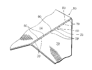
FIG. 1 shows a tongue-lid cigarette package
immediately after produced. FIG. 2 shows the cigarette
package of FIG. 1 in an open state. As clear from FIG. 2,
the cigarette package comprises a parallelepiped outer box
2 and an inner pack 4 enclosed in the outer box 2. The
inner pack 4 includes a bundle of rod-shaped smoking
articles such as filter cigarettes, which will be called a
cigarette bundle CB, and an inner wrapper 6 covering the
cigarette bundle CB.
An outer box 2 includes a box body 8, and the box body
8 is open at the upper end. The outer box 2 further
includes a tongue lid 10, and the tongue lid 10 is joined
to the box body 8 at a rear edge of the open end of the box
body 8, which functions as a hinge. The tongue lid 10 has
a top wall 12 for closing the open end of the box body 8,
and a tongue 14 extending from the top wall 12. The tongue
14 has a tapered end.
When the cigarette package is in the state shown in
FIG. 1, the top wall 12 of the tongue lid 10 covers the
open end of the box body 8, and the tongue 14 of the tongue
lid 10 overlies the front wall 30 of the box body 8.
CA 02632756 2008-06-09
8 -
The tongue lid 10 further includes inner top flaps 16
in a pair and connecting lugs 20 in a pair. The inner top
flaps 16 in a pair are bonded to the inner surface of the
top wall 12 at the opposite ends. The connecting lugs 20
in a pair are bonded to the outer surfaces of the side
walls 18 of the box body 18, beside the open end of the box
body 18, respectively.
More specifically, each side wall 18 has an outer wall
18a and an inner wall 18b. When the cigarette package is
in the state shown in FIG. 1, each inner top flap 16 is
joined to an upper edge of the inner wall 18b of the
corresponding side wall 18 by a tearable top separation
line 24, while each connecting lug 20 is joined to the
corresponding side edge of the tongue 14 by a tearable side
separation line 26. The top separation lines 24 and side
separation lines 26 each consist of a perforated line.
As will be described later, the above-described outer
box 2 is formed by folding a blank of paper, in which
process, the top separation lines 24 and side separation
lines 26 serve as fold lines.
When the tongue lid 10 of the cigarette package
produced is first opened, namely, the tongue 14 of the
tongue lid 10 is pulled up from the front wall 30 of the
box body 2 and turned around the hinge, the tongue lid 10
is separated from the box body 8 along the top separation
lines 24 and the side separation lines 26, as shown in FIG.
2.
Here, as marked with diagonal lines in FIG. 2, the
separation along the side separation lines 26 leaves break
marks 28 on the side edges of the tongue 14 as well as the
connecting lugs 20 in a pair, and the separation along the
top separations lines 24 leaves break marks 28 on the inner
walls 18b and the inner top flaps 16. Even when the tongue
CA 02632756 2008-06-09
9 -
lid 10 is closed after this, the break marks 28 on the
tongue 14 and the connecting lugs 20 are exposed, namely
visible from outside. Thus, the provision of the
separation lines leaving the break marks 28 is effective in
deterring people from tampering with the filter cigarettes.
As clear from FIG. 1, the front wall 30 of the box
body 8 has a recess 32, and the recess 32 is similar in
shape to the end portion of the tongue 14. Thus, in the
process of producing the cigarette package, when the tongue
14 is laid on the front wall 30 of the box body 8, the
recess 32 receives the end portion of the tongue 14, so
that the end portion of the tongue 14 is prevented from
protruding beyond the surface of the front wall 30.
Further, as clear from FIG. 2, the front wall 30 has a
slit 34. The slit 34 is formed between the open end of the
box body 8 and the recess 32, and has a V-shape spreading
out from the recess 32 toward the open end of the box body
8.
When the tongue lid 10 is once opened and then closed,
the tongue lid 10 is laid on the front wall 30 of the box
body 8 with its end inserted into the interior of the box
body 8 through the slit 34. Desirably, the tongue lid 10
may have a fold line 36 near the end of the tongue 14.
When the end portion of the tongue 14 is bent toward the
front wall 30 of the box body 8 along the fold line 36, the
tongue lid 10 is more easily inserted into the slit 34.
Further, as clear from FIG. 2, when the tongue lid 10
is first opened, an approximately U-shaped notch 38 is
formed in the front wall 30 of the box body, and at the
same time an approximately U-shaped notch 40, similar to
the notch 38, is formed in the inner wrapper 6 of the inner
pack 4. The notches 38, 40 are continuous with the open
end of the box body 8 and conformity with each other. Thus,
CA 02632756 2008-06-09
- 10 -
the cigarette bundle CB of the inner pack 4 is allowed to
be partly exposed in the notches 38, 40.
As shown in FIGS. 3 and 4, for the notches 38, 40 to
be formed, the front wall 30 and the inner wrapper 6 have
separation lines 42, respectively. The separation lines 42
each consist of a row of holes or slits, and define to-be-
separated portions 44, 46 corresponding to the notches 38,
40 on the front wall 30 and the inner wrapper 6,
respectively. The to-be-separated portions 44, 46 are
bonded together by an adhesive 48. Further, the to-be-
separated portion 44 is bonded to the inner surface of the
tongue 14 by an adhesive 50 and the to-be-separated portion
46 includes a top portion 46t bonded to the inner top flaps
16 in a pair by an adhesive 52.
In FIG. 3, reference sign 54 denotes an adhesive
bonding the inner top flaps 16 and the top wall 12 of the
tongue lid 10 together.
FIG. 4 clearly shows the shape of the to-be-separated
portion 46 of the inner wrapper 6 and the positions of the
adhesives 48, 52 applied on the to-be-separated portion 46.
FIG. 5 shows the inner wrapper 6 in an unfolded state.
The broken lines in FIG. 5 indicate fold lines produced on
the inner wrapper 6 when the cigarette bundle CB is wrapped
in the inner wrapper 6. In the present embodiment, the
inner wrapper 6 includes glassine paper layers forming the
outer and inner sides of the inner wrapper, and a paraffin
wax layer between the glassine paper layers. The paraffin
wax layer functions as a blocking layer, so that the inner
wrapper 6 is higher in moisture-blocking capability as well
as flavor-blocking capability, compared with aluminum-
deposited paper. Thus, this embodiment of cigarette
package does not require a film covering the outer box 2.
As mentioned above, when the tongue lid 10 is first
CA 02632756 2008-06-09
- 11 -
opened, the to-be-separated portions 44, 46 of the front
wall 30 and the inner wrapper 6 are separated from the
front wall 30 and the inner wrapper 6 along the separation
lines 42 to form separated pieces 56, 58, respectively. As
clear from FIG. 2, the separated pieces 56, 58 are kept
bonded to the inner surface of the tongue lid 10.
FIGS. 6 and 7 show the above-mentioned side separation
line 26 on an enlarged scale.
The side separation line 26 consists of a perforated
line, and the perforated line has alternating slits 59 and
fatigued joins 60. The fatigued joins 60 are formed by
applying a specified load to the side separation line 26
from the inner side of the blank.
Also the top separation line 24 consists of a
perforated line similar to the side separation line 26 and
has alternating slits and fatigued joins.
The linkage of fibers constituting the blank is broken
at the locations of the top and side separation lines 24,
26, and such breaks about the linkage of fibers develop
when the blank is folded along the top and side separation
lines 24, 26. Thus, in the outer box 2 that has been
formed from the blank, the fatigued joins 60 in the top and
side separation lines 24, 26 have strength further
decreased.
Thus, when the tongue lid 10 is first opened, a crack
infallibly runs from one end to the other end of each of
the separation lines 24, 26, breaking the fatigued joins 60,
so that the tongue lid 10 is separated from the box body 8
in a good manner. As a result, undesired breaks deviating
from the separation lines 24, 26 are not produced in the
tongue lid 10 or the box body 8.
FIG. 8 shows a blank 62 for forming the above-
described outer box 2.
CA 02632756 2008-06-09
- 12 -
The blank 62 includes a plurality of panels and flaps.
These panels and flaps form the above-described box body 8
and tongue lid 10. The panels and flaps are assigned the
same reference signs as those assigned to the corresponding
constituting parts of the box body 8 and tongue lid 10.
Reference signs 8r, 8b, 8ib in FIG. 8 denote a rear wall, a
bottom wall, and inner bottom flaps for reinforcing the
bottom wall, of the box body 8, respectively.
In FIG. 8, fold lines for the blank 62 other than the
top and side separation lines 24, 26 are indicated in
double thin lines, and reference signs (I) to (VI) indicate
the order of folding of the blank 62 along the fold lines
and separation lines 24, 26.
The above-mentioned fatigued joins 60 of the top and
side separation lines 24, 26 are formed prior to folding
the blank 62. How the fatigued joins 60 are formed will be
explained below.
FIG. 9 shows a transport path 64 along which the blank
62 is transported. The transport path 64 extends
horizontally toward a folding station. The blank 62 is
placed on the transport path 64 with its outer side up. On
the transport path 64, a first folding position P1 and a
second folding position P2 are defined. At the first
folding position P1, fatigued joins 60 are formed in the
side separation lines 26 of the blank 62, and at the second
folding position P2, fatigued joins 60 are formed in the
top separation line 24 of the blank 62.
More specifically, at the first folding position P1,
the connecting lugs 20 in a pair of the blank 62 are folded
toward the outer side of the blank 62, namely upward, along
the side separation lines 26. This folding operation
applies a load to the side separation lines 26 from the
inner side of the blank 62, so that the portions between
CA 02632756 2008-06-09
- 13 -
the slits 59 of the side separation lines 26 are formed
into the fatigued joins 60.
Then, at the second folding position P2, the inner top
flaps 16 in a pair of the blank 62 are folded upward along
the top separation lines 24. This folding operation forms
the portions between the slits 59 of the top separation
lines 24 into the fatigued joins 60.
FIG. 10 specifically shows a first folding device 66
for forming the fatigued joins 60 in the side separation
lines 26.
The first folding device 66 includes movable plates 68,
70 in a pair. The movable plates 68, 70 are disposed below
and above the transport path 64, respectively, parallel to
the transport path 64, and capable of reciprocating
vertically in a manner associated with each other.
Specifically, a side edge of the movable plate 68 extending
along the transport path and the corresponding side edge of
the movable plate 70 are joined by a vertical plate 71.
Tuckers 72a, 72b in a pair are provided below the
transport path 64. The tucker 72a is located immediately
upstream of the movable plates 68, 70, while the tucker 72b
is located immediately downstream of the movable plates 68,
70. When the movable plates 68, 70 in a pair are in a rest
position as shown in FIG. 10, the tuckers 72a, 72b in a
pair and the lower movable plate 68 are at the same height
position.
The tuckers 72a, 72b in a pair are capable of
reciprocating along the transport path 64, and by such
reciprocation, the distance between each tucker 72 and the
movable plates 68, 70 is adjusted.
Downstream of the tucker 72b, a transport guide 74 is
provided. The transport guide 74 is located immediately
below the transport path 64.
CA 02632756 2008-06-09
- 14 -
As shown in FIG. 10, at the time the blank 62 has been
transported to the first folding position P1, the part of
the blank 62 intended to form the tongue 14 of the tongue
lid 10, i.e., the tongue panel is located between the
movable plates 68, 70, and the left and right side
separation lines 26 and connecting lugs 20 of the blank 62
are located upstream and downstream of the movable plates
68, 70, respectively. Here, it is to be noted that the
side separation lines 26 extend in the direction crossing
the transport plane on which the blank 26 is transported.
When the movable plates 68, 70 in a pair are moved
down from the position shown in FIG. 10, the upper movable
plate 70 pushes down the tongue panel with the connecting
lugs 20 in a pair, in this process, the tuckers 72a, 72b in
a pair contact the connecting lugs 20, respectively,
thereby preventing the connecting lugs 20 from moving down.
Consequently, as shown in FIG. 11, the connecting lugs 20
are folded along the side separation lines 26, respectively,
so that the fatigued joins 60 are formed in the side
separation lines 26.
It is to be noted that the tongue panel is pushed down
in a manner that the blank 62 is folded along the fold line
between the panel intended to form the rear wall 8r and the
panel intended to form the top wall 12, or in other words,
along the hinge line. The angle to which the connecting
lug 20 is folded, therefore the load applied to the side
separation line 26 is determined by the distance between
the tucker 72 and the movable plate 70.
Then, as shown in FIG. 12, the movable plates 68, 70
are moved up to return to the rest position, where the
lower movable plate 68 brings the tongue panel back to the
same level as the tuckers 72a, 72b. Thus, after this, when
the blank 62 is again transported along the transport path
CA 02632756 2008-06-09
- 15 -
64, the blank 62, specifically the folded connecting lugs
20 are not obstructed by the downstream tucker 72b. Guided
by the transport guide 74, the blank 26 moves toward the
subsequent second folding position P2-
It can be arranged that the movable plate 68 in the
rest position and the tuckers 72a, 72b are located
immediately under the transport path 64. In this case, the
plate 68 and tuckers 72 serve as blank 62 transport guides.
FIG. 13 shows a second folding device 76 provided at
the second folding position P2.
The second folding device 76 includes a receiving
roller 78, and the receiving roller 78 is located
immediately below the transport path 64. The receiving
roller 78 is supported rotatably, and guides the transport
of the blank 62 with its cylindrical surface. The
cylindrical surface has a circumferential groove 80. In
FIG. 13, the one-dot chain line indicates the rotation axis
of the receiving roller 78, and reference sign 82 denotes a
guide member defining the transport path 64.
Above the receiving roller 78, a rotating drum 84 is
located. A plurality of tucker blocks 86 are attached to
the peripheral portion of the rotating drum 84. As clear
from FIG. 14, the tucker blocks 86 are arranged along the
circumference of the rotating drum 84, at specified
intervals, and projects radially outward beyond the
cylindrical surface of the rotating drum 84.
More specifically, each tucker block 86 includes a
holder 88 fixed to the rotating drum 84 and a tucker 90
held by the holder 88. The tucker 90 projects radially
outward of the rotating drum 84, beyond the holder 88. The
projection of the tucker 90 is adjustable by means of
adjusting screws 92 and slots 94. The tucker 90 has a
circular arc surface 90a at the projecting end. The
CA 02632756 2008-06-09
- 16 -
trajectory K described by the circular arc surface 90a when
the rotating drum 84 is rotated is partly under the
transport path 64.
The blank 62 is transported to the second folding
position P2, and one of the top separation lines 24 of the
blank 62 arrives right above the circumferential groove 80
in the receiving roller 78 as shown in FIG. 13. Here, it
is to be noted that the top separation lines 24 extends in
the direction of transport of the blank 62.
On the other hand, immediately before the top
separation line 24 arrives at the position of the
circumferential groove 80, intermittent rotation of the
rotating drum 84 is started, and at the same time as the
top separation line 24 arrives, the tucker 90 of one of the
tucker blocks 86 passes along the top separation line 24,
where, as shown in FIG. 15, the tucker 90 pushes the top
separation line 24 into the circumferential groove 80 of
the receiving roller 78, thereby folding the associated
inner top flap 16 upward along the top separation line 24.
Thus, a load is applied to the top separation line 24 from
the inner side of the blank 62, so that the fatigued joins
60 are formed in the top separation line 24.
Since the tucker 90 passes along the top separation
line 24 while the receiving roller 78 is guiding the
transport of the blank 62, the blank 62 does not undergo an
excessive load.
Then, the blank 62 is transported along the transport
path 64 for the distance corresponding to the distance
between the inner top flaps 16 in a pair, so that the other
top separation line 24 is positioned right above the
circumferential groove 80 in the roller 78. At the same
time as the other top separation line 24 is thus positioned,
the tucker 90 of the next tucker block 90 passes along this
CA 02632756 2008-06-09
- 17 -
top separation line 24, pushing it into the circumferential
groove 80. Consequently, the fatigued joins 60 are formed
also in this top separation line 24 in the same manner.
Then, the blank 62 is further transported along the
transport path 64 toward the folding station. At the
folding station, the blank 62 is folded around the inner
pack 4 according to the process shown in FIGS. 16 to 18.
First, as shown in FIG. 16, the inner pack 4 is
supplied onto the inner side of the blank 62. The inner
pack 4 is placed on the rear wall panel 8r of the blank 62,
and the left and right side flaps 18b are each folded
toward the corresponding side face of the inner pack 4,
together with the associated inner top flap 16 and inner
bottom flap 8ib, to overlie the corresponding side face of
the inner pack.
Then, as shown in FIG. 17, the inner top flaps 16 and
the inner bottom flaps 8ib are folded toward the inner pack
4 to overlie the top face and bottom face of the inner pack
4, respectively.
Then, together with the tongue panel 14, the top wall
panel 12 is folded toward the top face of the inner pack 4
so that the top wall panel 12 overlies the inner top flaps
16. At the same time as the top wall panel 12 is folded,
the bottom wall panel 8b with the front wall panel 30 is
folded toward the bottom face of the inner pack 4 so that
the bottom wall panel 8b overlies the inner bottom flaps
8ib.
Then, the front wall panel 30 with the left and right
side flaps 18a is folded toward the inner pack 4 so that
the front wall panel 30 overlies the front face of the
inner pack 4. Later than the front wall panel 30 is folded,
the tongue panel 14 with the left and right connecting lugs
20 is folded toward the inner pack 4 so that the tongue
CA 02632756 2008-06-09
- 18 -
panel 14 overlies the front wall panel 30 and the
connecting lugs 20 overlie the side flaps 18a, respectively,
as shown in FIG. 18.
Last, the left and right side flaps 18a with the left
and right connecting lugs 20 on are folded toward the inner
pack 4 so that the side flaps 18a with the connecting lugs
20 overlie the side flaps 18b, respectively. With this,
the production of the cigarette package is completed.
In FIGS. 16 and 17, hatching and cross-hatching are
used to indicate the areas where an adhesive is applied.
Apart from this, the tongue panel 14 is bonded to the front
wall panel 30 by an adhesive 14a allowing detachment.
In the above-described method of producing the
cigarette package, prior to folding the blank 62, the
fatigued joins 60 are formed in the top and side separation
lines 24, 26 of the blank 62 in the above-described manner.
The linkage of fibers constituting the blank 62 are broken
at the locations of the fatigued joins, so that the
fatigued joins 60 are lower in tensile strength than the
other part of the blank 62. After this, when the inner top
flaps 16 and connecting lugs 20 are folded along the top
and side separation lines 24, 26, respectively, breaks
about the linkage of fibers at the locations of the
fatigued joins 60 of the top and side separation lines 24
further develop.
The present invention is not limited to the above-
described embodiment but can be modified in various ways.
For example, the present invention is applicable not
only to the tongue-lid cigarette package but also to common
hinged-lid cigarette packages in a similar manner. Further,
it may be arranged such that before the fatigued joins 60
in the side separation lines 26 are formed, the fatigued
joins 60 in the top separation lines 24 are formed.
CA 02632756 2008-06-09
- 19 -
Further, the cigarette package according to the present
invention may be provided with only the side separation
lines 26 of the top and side separation lines 24, 26.