Note : Les descriptions sont présentées dans la langue officielle dans laquelle elles ont été soumises.
CA 02633852 2008-06-10
WO 2007/057202 PCT/EP2006/011054
Hinged partition and arrangement for closing off a room against a fluid
flowing into the room or
out of the room
The object of the invention refers to an arrangement for closing off a room
against a
fluid flowing into the room or out from the room, especially a combustible
fluid.
It is known that doors or passageways of a room, especially of a workshop or
of a storage
room can be closed off by partitions. A hinged partition is to ensure that a
fluid cannot leave a
room or enter into this room. The fluids can be water. chemicals, oils or
their mixtures. Such
fluids or fluid mixtures occur especially when water used for fire
extinguishing by the fire
department or by a sprinkling installation is pumped into the room. Moreover,
especially in the
case of hazardous material storage, there is a necessity to close off the
storage against the exit of
fluids into the surroundings.
A room is defined not only as a building or a part of a building, such as, for
example an
underground parking structure, a workshop, a storage room, etc.. but also
areas delimited by
boundaries, for example walls, that have at least one opening, for example in
the form of a
passageway which must be closed as needed.
Various embodiments of arrangements for closing off a room against a fluid
flowing into
the room or out of the room are known. Fronl t1S 5,460,462, a device for
closing off is known in
which a partition can be extended in a vertical direction. When this partition
is extended, it
forms a barrier.
Another embodiment for closing off a room is known from EP 0 586 356 Al. This
has a
flexible barrier which is formed by a tarpaulin. This tarpaulin is located in
the floor and is
connected to a pivotable tie-bar with which the tarpaulin is raised.
EP 0 754 822 A2 describes a device for closing off a room. The device has a
partition
that can be pivoted around an essentially horizontal axis and which can be
lifted up by a drive
from a recess provided in the floor of the room, as a function of a fluid
entering into the recess.
This hinged partition is designed as a float. The drive comprises at least one
weight which can
be moved essentially vertically, and which is connected to a drive that can be
pivoted with the
axis around the hinged partition. The weight causes a torque around the axis,
which is greater
than the torque acting around the axis by the gravitational force of the
hinged partition when the
1
CA 02633852 2008-06-10
WO 2007/057202 PCT/EP2006/011054
hinged partition has been deviated from its essentially horizontal position in
the recess by the
fluid entering into the recess.
The hinged partition will lie against a seal, which is arranged in a
corresponding frame
that partially surrounds the opening. It is known that such a seal has an
essentially rectangular
cross-section. This elastically designed seal is intended to ensure that a
fluid cannot enter into
the room or leave the room. The problem in such a device is that, due to the
manufacturing
tolerances, an expensive alignment of the axis or of the hinged partition is
necessary in order to
ensure that the sealing function will be reached to a sufficient extent. Due
to the large evolution
of heat that occurs during fires, the problem arises that the coniponents of
the device behave
differently thermally and the sealing function cannot be assured or can be
assured only to a
reduced extent.
A device for closing off a room against a fluid flowing into the room,
especially water, is
known from GB 2 403 254 A. The device has a pivotable hinged partition, which
can be pivoted
from a first position into a second position around an axis. The hinged
partition has a flexible
seal that has flaps protruding through an edge of the hinged partition running
transversely to the
longitudinal axis, and these flaps can be folded. The seal and the flaps are
connected to the
hinged partition through a frame, which is attached to the wall of the
building. This measure is
intended to ensure that entry of a fluid on the side between the hinged
partition and the frame
does not occur.
Based on this, the task of the present invention is to provide an arrangement
for closing
off a room against a fluid flowing into the room or out from the room,
especially a combustible
fluid, which essentially ensures that no fluid leaves the room or enters into
the room even at high
temperatures, especially in the case of a fire.
This task is solved according to the invention by an arrangement for closing
off a room
against a fluid flowing into the room or out of from the room, especially a
combustible fluid,
with the characteristics of Claim 1. Advantageous further embodiments of the
invention are the
objects of the dependent claims.
The arrangement according to the invention for closing off a room against a
fluid flowing
into the room or out from the room, especially a combustible fluid, has a
hinged partition which
can be pivoted from a first position into a second position around an axis, as
well as a frame. A
seal that is at least partially flexible is provided, which has at least one
flap protruding beyond an
2
CA 02633852 2008-06-10
WO 2007/057202 PCT/EP2006/011054
edge running transversely to the axis, and this flap is joined to the hinged
partition and to the
room. At least one screening means is provided near the at least one flap.
With this design of the arrangement according to the invention, an improved
sealing is
achieved. The flexible seal is connected on the one side to the hinged
partition and on the other
side to a frame that is present in the area of a passageway or an opening, so
that the sealing
function is always present, especially independently of the position of the
hinged partition.
The design of the arrangement according to the invention also makes simple
mounting
possible, since the sealing function now is almost independent of the position
of the axis or of the
hinged partition. Moreover, the arrangement according to the invention has the
advantage that
replacement of the seal is simplified. Thus now, in contrast to the state of
the art, a specially
trained person is not necessary for replacing the flexible seal.
The hinted partition can be pivoted around an axis from a first position into
a second
position. The second position can be a variable position. There is the
possibility that, depending
on the level of a fluid, the hinged partition will float up from a first
position into a second
position, which is dependent on the fluid level. The advantage of such an
arrangement is that the
hinged partition automatically returns to the first position when the level of
the fluid drops again.
The flexible seal is preferably a seal that is sheet-like in design.
Especially it is proposed
that the seal be made at least partly of a plastic, especially of
polytetrafluoroethylene (PTFE).
The properties of the seal can be easily adapted to the requirements. Thus,
for example it
is possible to manufacture the seal from a material that is resistant, for
example, to aggressive
media, for example acids, oils, gasoline, etc. There is also the possibility
of producing the seal
from a material that has an appropriately high melting point. Especially it is
proposed that the
seal be made of a material that is stable even at high temperatures.
Especially, it is proposed that
the seal be made of a material that has an ignition temperature of at least
150 C, preferably
220 C.
According to an advantageous embodiment of the arrangement according to the
invention, it is proposed that the seals neighboring the axis have strips that
project beyond the
hinged partition. Hereby the dimensions of the strip are such that it bridges
the gap between the
hinged partition and, for example, a frame, whereby the strip is attached to
the frame. In order to
ensure that the seal will not be damaged, for example, by vehicles or similar
when the hinged
CA 02633852 2008-06-10
WO 2007/057202 PCT/EP2006/011054
partition can be driven over, it is proposed that a drive-over protection be
arranged over the seal.
This drive-over protection can be made in the form of a pivotable cover, so
that when the hinged
partition is pivoted from a first position into a second position, the drive-
over protection is also
pivoted. As a result of this, blocking of the movement of the hinged partition
by the drive-over
protection is avoided.
Preferably it is proposed that tightening means be provided through which the
flap can be
tightened. The tightening means brings the flap into a suitable position when
the hinged partition
performs the closing function. The tightening means may have different
designs. A design is
preferred in which the tightening means is in the shape of loops. Especially
it is proposed that a
tightening means be provided in or at the edge region of the flap.
Through this arrangement according to the invention, an improved sealing
fiulction is
achieved. This is true especially when the components of the arrangement have
different thermal
behavior as a result of the evolution of heat, and so that the difference in
the thermal expansion
of the frame and of the hinged partition is compensated by the at least
partially flexible seal.
Another advantage of the device according to the invention for closing off a
room against
a fluid that flows into the room or out from the room can be regarded in the
fact that the
mounting of the device is simplified, since, through the flexible seal, the
tolerance regarding the
positioning of the axis can be compensated by the seal.
Due to the fact that near the at least one flap at least one screening means
is provided, it is
ensured that, especially upon exposure to higher temperatures, which is the
case when a fire
occurs, the flexible seal is protected, so that a fluid cannot flow out of the
room or into the room.
Hereby an embodiment is preferred in which the screening means has a wall
arranged
essentially parallel to the edge of the hinged partition with the formation of
a gap. The wall is
preferably at least partly made of a material that is thermally stable at high
temperatures,
especially above 150 C. Especially preferred here is a design in which the
wall is made at least
partly from a fire-resistant material.
In order to further increase the protection of the seal against thernlal
effects. it is
proposed that the wall preferably have a multilayered structure.
4
CA 02633852 2008-06-10
WO 2007/057202 PCT/EP2006/011054
In order to prevent, for example, the action of the flames between the wall
and the edge
of the hinged partition on the seal, according to another further advantageous
embodiment it is
proposed that the edge have at least one lip, preferably a flexible lip, that
extends at least
partially in the longitudinal direction of the edge and lies against the wall.
According to a still further advantageous embodiment, it is proposed that a
barrier be
formed between the wall and the edge, made of a material that foams when a
predetermined
limiting temperature is exceeded. The material can preferably be a plastic,
with a propellant that
converts to the gaseous state upon exceeding a predetermined temperature and
thus leads to the
foaming of the plastic. Alternatively or additionally, the material can be a
thermoplastic material
that is compressed at ambient temperature and expands upon the action of heat.
The wall and/or the edge can be coated at least partly with such a material.
According to a still further advantageous embodiment of the arrangement, it is
proposed
that the hinged partition have at least one component that is moveable in the
direction of the
wall. This component is preferably designed so that the component will lie
against the wall
when the hinged partition is pivoted from the first position into the second
position. Herebv a
triggering mechanism can be provided, which releases the component, which is
preferably under
spring tension, so that this component is moved in the direction of the wall.
Through this
measure an essentially flame-proof closure between the hinged partition and
the wall is achieved.
According to a still further advantageous embodiment of the invention, it is
proposed that
at least one essentially curved cover be provided, which covers the wall and
an edge region of
the hinged partition at least partly. Through this curved cover it is ensured
that for example
combustible fluids cannot enter into the region of the side seals of the
hinged partition.
According to a still further advantageous embodiment of the device, it is
proposed that at
least one essentially curved flame section can be provided which has at least
one flame opening.
As a result of this, flames rising under the hinged partition are guided away
by hydraulic
technology so that the thermal load on the seal is reduced.
The air flow or the direction of the flames can be influenced further by the
fact that the
flame segment is arranged below the cover. The flow of the flames can be
influenced by the
number and design of the flame openings. Additionally, flow guide bodies may
be provided in
the area of the flame opening.
CA 02633852 2008-06-10
WO 2007/057202 PCT/EP2006/011054
In order to protect especially the side seal from direct effect of flames,
according to a still
further advantageous embodiment of the arrangement, it is proposed that, in
the area of the flaps,
segments that can be pushed into one another in a fan-like manner may be
provided.
According to a still further advantageous embodiment of the invention it is
proposed that
a drive be provided with the aid of which the partition can be pivoted around
the axis. Hereby an
embodiment is especially preferred in which a locking device is provided with
the aid of which
the partition is kept in the first position. A triggering device is connected
to the locking device
by means of which the partition is released so that the partition can be
swiveled into the second
position. With the aid of this advantageous embodiment of the device, it is
achieved that the
hinged partition can be moved from a first position into a second position
only when a fluid is
present. With the aid of the locking device, manual manipulation of the
arrangement is also
prevented.
The hinged partition is preferably designed as a float. The design of the
hinged partition
as a float limits the selection of the materials to be used. Moreover, the
hinged partition must
satisfy numerous requirements, for example that heavy equipment can travel
over it, that it be
heat resistant, mechanically stable and exhibit stability towards aggressive
materials. This can
have an adverse effect on the cost. Corresponding conditions apply to the
application of
additional floats since then additional space is also required. If the hinged
partition is designed
so that it is no longer floatable, then the gravitational force of the hinged
partition must be
compensated for by the application of additional forces. Such a compensation
can be achieved,
for example, by using springs.
The application of springs to the hinged partition is advantageous especially
when the
weakening spring action is compensated by an increase of the hydrostatic
pressure. By the rotary
movement of the hinged partition, the path of the spring is altered, which
leads to a weakening of
the spring force. The hydrostatic pressure increases with increasing height of
the liquid level.
Through the rotary movement of the hinged partition from the horizontal
position into the
vertical position, the torque caused by the weight of the hinged partition
itself is reduced. In the
combination of these forces, the decreasing spring force is compensated by
suitable setection of
the springs.
6
CA 02633852 2008-06-10
WO 2007/057202 PCT/EP2006/011054
Instead of springs, at least one counterweight may also be used. For this
purpose,
optionally corresponding deflection pulleys are necessary so that the hinged
partition can be
transferred from the horizontal into the vertical position by the
gravitational force of the
counterweights. Through the resulting total course of the momentum, it is
achieved that the
hinged partition lies in the liquid for the most part at different liquid
levels and the components
lying above it are protected ideally from the flames and also the hinged
partition is cooled by the
fluid.
Application of springs directly on the surface of the hinged partition is
especially
advantageous. Tension springs and pressure springs are especially suitable for
this. No
additional complex means are needed for applying the at least one spring.
Moreover, an
essentially smooth sideways closure of the hinged partition is created. In
this way the
application of heat insulation and flame retardants is much simplified, since
no expansion for
shafts or holding elements for introducing the force is necessary. The
application of the at least
one spring is very simple and cost-effective. The spring can be applied above
the hinged
partition, as a result of which it is protected against heat and flame.
An embodiment in which at least one spring is arranged so that a tangential
course of the
spring force line occurs only after rotation of the hinged partition around
its axis is especially
advantageous. This is achieved especially when the angle between the sections
of pivot point-
force application and pivot point-spring attachment is greater than 90
degrees.
It is especially advantageous when the cross-section of the hinged partition
is essentially
wedge-shaped. In this way, a defined position of the hinged partition in a
fluid is also achieved.
The thickness of the hinged partition preferably decreases in the direction of
the rotary axis.
Moreover, the wedge-shaped design of the hinged partition has the advantage
that the total
weight of the hinged partition will be reduced. The reduction of the thickness
of the barrier in
the direction of the rotary axis has the advantage that the center of gravity
and the midpoint of
the lifting force are removed further from the pivot point. In this way better
self-adjustment of
the floating height is achieved, since the partition, when this is immersed
further into the liquid,
experiences a greater increase in the lifting force than when the barrier is
designed to have a
constant thickness. Similarly, when the partition rises further out of the
fluid, a larger decrease
of the volume available for buoyancy is achieved. Moreover, the incorporation
of the hinged
partition or of the arrangement is simplified with the aid of a pouring
method, especially a
concrete pouring method. As a result of the essentially wedge-shaped design of
the hinged
partition, essentially no air can collect under the hinged partition, which
leads to the fact that the
7
CA 02633852 2008-06-10
WO 2007/057202 PCT/EP2006/011054
hinged partition will not be flooded underneath correctly, as a result of
which the trough will not
be attached correctly. This can lead to a bowing upward of the trough in which
the hinged
partition is arranged at these locations, and therefore the hinged partition
will be pivoted away
from the actually intended position and thus will no longer lie flat on the
bottom. For example, if
a vehicle drives over the hinged partition then the areas that are bowed
upward will undergo a
greater load, which may lead to a stress of the hinged partition since
additional shifting of the
load does not occur.
If springs are used for moving the hinged partition, then it is especially
advantageous for
the springs to be chosen so that the hinged partition can be pivoted manually
with a sniall manual
force over the entire pivoting range. This simplifies the cleaning and manual
checking of the
functioning of the hinged partition. Moreover, the danger of injury to the
operator is highly
reduced in this way. It is of especially great advantage when the spring force
is adjusted so that
the hinged partition after manual operation will be stopped automatically in
the vertical position.
In this way the cleaning of the barrier is simplified even further.
Other advantages and details of the hinged partition according to the
invention as well as
the arrangement according to the invention will be explained with the aid of
the practical
examples shown in the drawing, without the object of the invention being
limited to these
practical examples.
The following are shown:
Figure 1 is a perspective view of the a hinged partition,
Figure 2 is a cross-section of the hinged partition according to Figure 1,
Figure 3 shows schematically an arrangement for the closing off of a room,
Figure 4 is a sectional view of the arrangement,
Figure 5 is a schematic and a perspective view of a hinged partition with
walls,
Figure 6 is an embodiment of an arrangement in a front view and in cross
section with a
moveable insulation.
Figure 7 shows a first practical example of an arrangement with segmented
screening means,
Figure 8 shows a second practical example of the arrangement with segmented
screening
means,
Figure 9 shows a first practical example of the arrangement with a curved
cover,
Figure 10 shows a practical example of the arrangement with a curved flame
segment,
8
CA 02633852 2008-06-10
WO 2007/057202 PCT/EP2006/011054
Figure 11 shows a practical example of the arrangement with a curved cover and
a curved flame
segment,
Figure 12 shows schematically a hinged partition with a spring suspension,
Figure 13 is an example of the variation of the momentum of the hinged
partition as a fi.inction
of the angle at the maximum possible liquid level,
Figure 14 shows the arrangement of a spring in a side view,
Figure 15 is a diagram of the course of the torque,
Figure 16 shows schematically a hinge connection of the hinged partition in a
top view, and
Figure 17 shows the hinged partition according to Figure 16 in a side view.
Figure 1 shows a perspective view of a practical example of a hinged partition
1 of an
arrangement for closing off a room against a fluid flowing into the room or
out from the room,
especially a combustible fluid. The hinged partition 1 is formed by a
prismatic body in this
representation, which can be sunk into a recess of a floor, the recess not
being shown. The
hinged partition 1 can be pivoted around an axis 2 from a first position into
a second position.
For example, the hinged partition 1 can have a metallic surface. It can be
formed by a box made
of metal in which a core is arranged that can be, for example, made of a
plastic or similar
material. A flame-retardant layer may be arranged between the core and the
outer mantle.
In the practical example shown, the hinged partition I is connected to a seal
3. The seal 3
can be made of one or several parts. The seal 3 is designed in a sheet-like
manner. Preferably it
is made of polytetrafluoroethylene.
Next to the axis 2, the seal 3 has a strip 4. The strip 4 is connected to the
hinged partition
1 through a cover strip 12. The joint is preferably constructed so that it is
separable, for
example, by having the cover strip 12 be screwed onto the hinged partition, so
that the strip 4 of
the seal 3 is clamped tightly onto the hinged partition 1, as can be seen from
Figure 2. The width
of the strip 4 is dimensioned so that the strip 4 can be attached to the frame
or floor, not shown,
of the opening, which can be closed by the hinged partition.
Next to the edges 5 of the hinged partition 1, running transversely to the
axis 2, flaps 6
are provided which form a part of the seal 3. The flaps 6 extend essentially
over the entire length
of edge 5. The blank of flaps 6 is chosen so that it is essentially in the
shape of a quarter circle.
9
CA 02633852 2008-06-10
WO 2007/057202 PCT/EP2006/011054
It can be seen from the representation in Figure 2 that. in the edge region 9
of the flaps 6,
openings 13 are provided, which form a part of the tightening means for
tightening the flaps 6.
The flaps 6 are attached to the hinged partition 1 with cover strips 14.
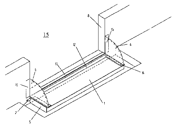
Figure 3 shows a practical example of an arrangement according to the
invention for
closing off a room against a fluid flowing into the room or out from the room,
especially a
combustible fluid. The device has a hinged partition 1, which can be pivoted
from a first
position into a second position around an axis 2. The hinged partition 1 is
sunk into a recess in
the floor, so that one can drive through or walk through a passageway 15. The
hinged partition 1
has flaps 6 on the side, which are attached to the frame 8 with fixing means
16. The frame 8 can,
be, for example, the masonry of a passageway. It is also possible for the
frame 8 to be, for
example, a steel construction.
The strip 4 is also placed on frame 8 by means of a cover strip 17.
A second embodiment of the arrangement is shown in Figure 4 in a cross-
section. The
arrangement has a hinged partition 1, which corresponds essentially to the
hinged partition I
according to Figure 1. The hinged partition 1 has a seal 3 which has a strip
4. The strip 4 is
attached by means of cover strip 12 to hinged partition 1 and by means of
cover strip 17 to the
frame 8. Over the strips and preferably over the entire width of the
passageway 15, a drive-over
protection 18 is arranged. The drive-over protection 18 can be swiveled around
an axis 19, so
that through the pivoting movement of the hinged partition 1, the drive-over
protection 18 is also
pivoted.
A wall 11 is arranged parallel to edge 5 of the hinged partition 1, which has
a side
protection of flap 6. Preferably a gap is formed between edge 5 and wall 11
that is smaller than
1 cm. Optionally, ribs can be formed on edge 5 through which the gap between
the edge 5 and
wall 11 is reduced. Rings 20 extend through the openings 13 of flap 6 and
these are guided on a guide means
10. The guide means 10 and the rings 20 form a tightening means 7 through
which the flap 6 is
tightened when the hinged partition I is transferred from the horizontal
position into a vertical
position.
In the practical examples shown, the hinged partition 1 can be pivoted around
an
essentially horizontally running axis 2. This is not absolutely necessary. The
possibility also
CA 02633852 2008-06-10
WO 2007/057202 PCT/EP2006/011054
exists for the hinged partition 1 and the axis 2 to be arranged in such a way
that pivoting around
a, for example, essentially vertical axis is made possible.
The hinged partition 1 may be made as light construction in which the core of
the hinged
partition is equipped with an extremely light and compression-resistant
material that permits
application of a high load to the hinged partition. Preferably, the hinged
partition is designed so
that, for example, even vehicles can drive over the hinged partition.
Especially, the hinged
partition is arranged in a trough, which is not shown, whereby the surface of
the hinged partition
is flush with the top side of the trough when the hinged partition is in the
first position. As a
rule, the trough is arranged in front of a passageway 15. The passageway 15
can be, for
example, a gate, a door or similar. Preferably, the hinged partition has
dimensions such that in
the second position of the hinged partition this will extend at least over the
entire width of the
passageway so that no fluid can flow through the passageway into a neighboring
room or into the
surroundings of the room.
The hinged partition can be equipped with a drive. For example this can be a
drive as is
also known from EP 0 754 822 A I.
Preferably, the hinged partition or the arrangement is designed in such a way
that a
locking device is provided with which the hinged partition is held in the
first position. A
triggering device cooperates with the locking device so that the hinged
partition is released for
pivoting it into the second position. Preferably the triggering device has a
unit with which the
level of a fluid is detected. The unit can be arranged next to the hinged
partition. However, this
is not absolutely necessary. The triggering device can also be arranged in
another location,
especially where the probability is the greatest of the fluid occurring before
it reaches the hinged
partition.
A control device is connected to the triggering device. The control device
produces some
old [literal] signals to the triggering device, so that the triggering device
can be activated or not.
The opening-oriented device is especially suitable for locations where the
danger of fire
is relatively high.
Figure 5 shows a practical example of an arrangement for closing off a room
against a
fluid flowing into the room or out from the room. The arrangement has a hinged
partition I and
11
CA 02633852 2008-06-10
WO 2007/057202 PCT/EP2006/011054
a frame 8. The flaps arranged on the side of a seal are not shown in Figure 5.
This seal is joined
to the frame and the hinged partition.
Figure 5 shows a screening means 21. The screening means 21 is formed by two
essentially parallel walls 22, 23, which are fixed in their location in the
practical example shown.
The walls 22, 23 form a multilayer wall. Wall 22 preferably consists at least
partially of a
material that is stable at high temperatures, especially above 150 C.
Especially wall 22 is made
at least partially from a fire-resistant material. The wall 23 preferably
serves as a mechanical
protection against applications of force onto wall 22.
Figure 6 shows another practical example of an arrangement for closing off a
room.
The arrangement has two walls 22, 23 that are essentially parallel to one
another and are
arranged at a distance from one another. For example, a filler may be provided
between walls
22, 23 through which the fire resistance of the screening means is increased
even further. A first
insulating element 24 is provided at the edge 5 of the hinged partition I in
the longitudinal
direction of edge 5. The first insulating element 24, with a projection 25
preferably forms a
guide 26 in which a second insulating element 27 is arranged. The second
insulating element 27
lies against wall 22. At least one spring element 28 is arranged between the
second insulating
element 27 and the hinged partition 1, so that the second insulating element
27 is pressed against
wall 22. The insulating elements 24, 27 form an additional flame protection,
so that a seal,
which is not shown, is not directly exposed to the flames.
In the embodiment shown, the insulating elements 24, 27 form at the same time
a kind of
labyrinth seal, which can be complemented by additional insulating elements.
In the practical
examples shown in Figures 5 and 6, the walls 22, 23 have a fixed location.
This is not absolutely
necessary. It is also possible for at least one of the walls, preferably wall
22, to be connected
solidly with the edge 5 of the hinged partition.
Figures 7 and 8 show additional practical examples of a screening means that
is suitable
and intended for the protection of a seal that is not shown here.
The screening means 21 according to Figure 7 is formed by segments 29, which
can be
moved relative to one another and can be slid into one another. The segments
29 in the
representation according to Figure 7 have side walls 30, which are attached to
cover walls 31.
Two side walls 30 can, in each case be present, arranged parallel to one
another, and these are
joined together by the cover wa1131. It is also possible to form each of
segments 29 by a side
12
CA 02633852 2008-06-10
WO 2007/057202 PCT/EP2006/011054
wa1130 and a cover wall 31, whereby a wall is present that is not shown and
this wall is
essentially parallel to the side walls 30, which borders cover walls 31. The
segments 29 can be
pivoted around a common axis.
Figure 8 shows another practical example of an arrangement with a screening
means.
The screening means is formed by segments 29. The segments 29 have a common
curved cover
wall 31. A wall, not shown, is essentially parallel to segment 29 and is
joined to cover wall 31.
The segments 29 can be pivoted around a common axis.
Figure 9 shows a screening means 21, which is formed by an essentially curved
cover 32.
The cover 32 can be pivoted around an axis 33 which is essentially horizontal.
The support of
cover 32 is chosen so that the cover 32 can be shifted in the axial direction,
by means of which
any tolerances, thermal expansions or similar can be compensated. The
pivotability of the cover
32 also has the advantage that access is made possible for maintenance
purposes.
According to a still further advantageous embodiment of the arrangement, this
has a
screening means 21, which has at least one essentially curved flame segment
34, as shown in
Figure 10. The flame segment 34 has flame openings 35 so that flames that may
occur
underneath the flame segment 34 can pass through the flame openings 35. In the
region of flame
openings 35, flow elements 36 are provided so that a directed flow of the
gases through the flame
openings and away from these elements is achieved.
Figure 11 shows a combination of a cover 32 in connection with a flame segment
34.
The cover 32 and the flame segment 34 are arranged at a distance from one
another, so that they
form a channe138. The channel 38 preferably has an exit orifice 37 on the
front through which
the hot gases can exit from channe138.
In order to move the hinged partition 1, preferably one spring 39 is arranged,
which is
joined to the frame 38 and the hinged partition 39. Hereby, expensive driving
means for flipping
up the hinged partition 1 can be omitted. Examples of changes of the momentum
of the hinQed
partition 1 as a function of angle at the maximum possible fluid level are
shown in Figure 13.
17
Decreasing spring action is compensated by the increase of the hydrostatic
pressure. Through
the rotary movement of the hinged partition, the spring path is changed, as a
result of which the
spring force of the spring is reduced. The hydrostatic pressure, which acts on
the hinged
partition, increases, however, with increasing fluid level. Through the rotary
movement of the
hinged partition from the horizontal position into the vertical position, the
lever arm also changes
13
CA 02633852 2008-06-10
WO 2007/057202 PCT/EP2006/011054
and thus the torque. By suitable selection of the spring, the decreasing
spring force is
compensated. Several springs may be present. The springs can also have
progressive spring
characteristics.
Figure 14 shows a second design of the arrangement for attaching a spring 39.
The
spring 39 is arranged so that the angle between the angle a of the imaginary
connecting lines
between the rotary axis and the two ends of the spring and of their attachment
points is greater
than 90 degrees. It can be seen from the representation according to Figure 15
that the resulting
momentum is almost constant as a function of the swing angle, as a result of
which when the
hinged partition is flipped up manually the force that has to be applied is
always constant as a
function of the angle.
The connection between the hinged partition 1 and the frame 8 is preferably
made with
hinges, as can be seen from Figure 16. An embodiment in which the hinges 40
are attached to
the top side of the hinged partition 1 is especially advantageous. Such a type
of attachment has
the advantage that the bottom side of the hinged partition is free from
joining means, which
simplifies the application of the fire resistant insulation materials, since
otherwise they would
have to have a bore or a recess or similar in order to provide a jointed
connection between the
hinged partition and the frame. Especially preferred hereby is a design in
which the hinges are
arranged so that free longitudinal expansion of the hinged partition is
possible.
An embodiment is preferred in which, for the protection of seal 3 in the
region between
the hinged partition and the frame, a cover is provided, which is preferably
attached to the hinged
partition and protrudes beyond the hinged partition far enough so that an even
and continuous
transition to the frame is ensured. This embodiment also opens up a drive-over
protection.
Driving over the hinged partition is thus possible without any differences in
height, which is also
advantageous at high speeds, especially for vehicles without spring action. A
low-noise or noise-
free travel over the hinged partition is achieved.
For even greater safety against leakage, it is proposed that the sealing with
the sheet-like
seal be combined with a sealing cord. For this purpose, in the lower range of
a possible liquid
level a sheet-like seal is used. In the upper range a sealing cord is used. In
this way the space
required for the side flaps is greatly reduced. In the case of pure sealing
with sheet, the space
requirement next to the hinge body is at least equal to the height of the
closing.
14
CA 02633852 2008-06-10
WO 2007/057202 PCT/EP2006/011054
If the arrangement according to the invention is used outside, especially
where water, for
example rain water can flow into the trough in which the hinged partition is
arranged, a problem
arises that an unintended floating up of the hinged partition may occur. In
this case it is
advantageous that the water, especially rain water, be collected in front of
the device with the aid
of a gutter and be led away before the liquid enters into the area of the
hinged partition. Liquid
can get all the way to the hinged partition only when this gutter is
overloaded and thus floods
over.
CA 02633852 2008-06-10
WO 2007/057202 PCT/EP2006/011054
List of reference numbers
1 hinged partition
2 axis
3 seal
4 strip
edge
6 flap
7 tightening means
8 frame
9 edge region
guide means
11 wall
12 side
13 opening
14 cover strip
passageway
16 fixing means
17 strip
18 drive-over protection
19 axis
ring
21 screening means
22 wall
23 wall
24 first insulating element
projection
26 guide
27 second insulating element
28 spring element
29 segment
side wall
31 cover wall
32 covering
33 axis
16
CA 02633852 2008-06-10
WO 2007/057202 PCT/EP2006/011054
34 flame segment
35 flame segments
36 flow element
37 exit opening
38 gutter
39 spring
17