Note : Les descriptions sont présentées dans la langue officielle dans laquelle elles ont été soumises.
CA 02635502 2008-06-20
1
2007P05583US (OSR 9838)
METAL HALIDE LAMP BALLAST CONTROLLED BY REMOTE ENABLE
SWITCHED BIAS SUPPLY
BACKGROUND
[0001] Metal halide lamps are preferred over halogen lamps in vehicle lighting
systems
(e.g., automotive headlight systems) because they emit more visible light per
watt and have a
longer life expectancy. Metal halide lamps can also be designed to emit
visible light with a
frequency profile similar to sunlight which improves visibility for a given
amount of light.
However, unlike halogen lamps, metal halide lamps cannot be driven directly
from a vehicle
power supply (i.e., a vehicle's charging system) and require the use of a
ballast. The ballast,
strikes the lamp, and adjusts the frequency and current applied to the lamp
such that the lamp
emits light of the proper intensity to achieve its design life.
[0002] Electronic ballasts include a controller which controls operation of a
power stage
for driving the metal halide lamp. The controller can be placed in a sleep
state such that the
ballast does not power the lamp which allows a low power switch or electronic
signal (e.g. a
signal provided by a vehicle's electronic control module) to turn the lamp on
and off.
However, in the sleep statc a relatively simple and inexpensive bias circuit
which provides
bias power to the controller draws a current large enough to drain the power
supply of the
vehicle over a relatively short period of time. For example, an electronic
ballast with the
controller in the sleep state can drain an automobile's battery over a weekend
such that the
vehicle's owner could not start the car at the beginning of the week without
providing
additional power to thc battery. A bias circuit and controller (e.g.,
microcontroller) which
reduce this sleep state bias power drain to an acceptable level can be
designed into the
electronic ballast, but are relatively complex and expensive.
[0003] Generally, there are three types of lighting control modules used in
vehicles that
may be used to control an electronic ballast. The first type is a relatively
bulky and expensive
high power switch, actuated by the vehicle operator, which provides power
directly from the
vehicle power supply to a lamp. The second type is a cheaper and smaller low
power switch,
actuated by the vehicle operator, which provides power from the power supply
to an
electromechanical relay. The low power switch can only provide enough power to
the relay
to actuate the relay; the relay provides substantially more power from the
vehicle power
supply to the lamp.
[0004] The third type of lighting control module is electronic. The electronic
lighting
control module receives user input and/or input from sensors (e.g., ambient
light sensors) and
CA 02635502 2008-06-20
2
2007P05583US (OSR 9838)
other sources to determine when to light a lamp. When the electronic lighting
control module
dctcrmincs that a lamp should be lit (e.g., the vehicle engine is running, the
transmission is in
drive, and there is little ambient light), it either provides power directly
to the ballast or
energizes an electromechanical relay which provides power from the vehicle
power supply to
the lamp ballast. Thus, the electronic lighting control module can be built
into an existing
electrical component of the vehicle such as an electronic control module.
However, the
electronic lighting control module must either be designed with the capacity
to provide a
relatively high source current required to power the ballast directly or must
utilize an
electromechanical relay to provide power to the ballast. Either solution (high
current
electronic lighting control module or the addition of an electromechanical
relay), adds a cost
to the vehicle lighting system.
[0005] FIG. 1 shows an example of a vehicle lighting using a vehicle lighting
control
module (e.g. a low power switch, a high power switch, or an electronic
control) to control a
relay which provides power to an electronic ballast as is known in the prior
art. Referring to
FIG. 1, a prior art electronic ballast 102 of a vehicle lighting system 100
provides power to a
lamp 104 in response to receiving power from a relay 106. In this prior art
system, a power
supply 108 (i.e., a vehicle charging system) of a vehicle comprises a battery
and an alternator
for providing power to electrical systems of the vehicle, including the
vehicle lighting system
100. In operation, an operator of the vehicle provides input to a vehicle
lighting control
module 110 (e.g., a headlight switch of the vehicle). Based on the operator
provided input,
the vehicle lighting control module 110 selectively energizes the relay 106.
That is, the
vehicle lighting control module 110 receives power from the vehicle power
supply 108 and
provides the received power to the relay 106 when the operator turns the
headlight switch on.
Conversely, the vehicle lighting control module 110 receives power from the
vehicle power
supply 108 but does not energize the relay 106 when the operator turns the
headlight switch
off.
[0006] When the vehicle lighting control module 110 energizes thc relay 106,
the relay
106 provides a supply voltage from the vehicle power supply 108 to an input
filter 112 of the
ballast 102. The input filter 112 filters noise from the supply voltage
provided by the relay
106 and provides the filtered supply voltage to a bias regulator 114 and a
power stage 116 of
the ballast 102. The bias regulator 114 receives the filtered supply voltage
and generates a
first bias voltage for a controller 118 of the ballast 102, and a second bias
voltage for the
power stage 116 of the ballast 102. The controller 118 controls the power
stage 116 to
CA 02635502 2016-01-20
=
3
provide power to the lamp 104. Thus, the ballast 102 provides power to the
lamp 104 in response to
receiving a supply voltage from the power supply 108 via the relay 106.
SUMMARY
[0007] In one embodiment, a vehicle lighting system includes a lamp, a
lighting control module,
and a ballast having a bias control circuit. The bias control circuit
energizes a bias regulator of the
ballast with power from a power supply as a function of a remote enable signal
provided by the
lighting control module. When the bias regulator receives power from the bias
control circuit, it
provides a first bias voltage to a controller of the ballast. The controller
controls a power stage of the
ballast to provide power to the lamp from the vehicle power supply. The bias
control circuit includes a
first switch and resistive pathways from an input of the first switch to
ground and a low side of the
first switch to ground. The first switch selectively energizes a first portion
of the bias regulator which
generates the first bias voltage for the controller. The bias control circuit
may also include a second
switch and resistive pathways from an input of the second switch to ground and
a low side of the
second switch to ground. The second switch selectively energizes a second
portion of the bias
regulator which generates a second bias voltage which is provided to the power
stage.
[0008] In another embodiment, there is provided a method of selectively
providing power from a
power supply to a lamp as a function of a remote enable signal. A bias control
circuit selectively
energizes a bias regulator in response to the remote enable signal provided in
an enable state. The bias
regulator provides a first bias voltage and a second bias voltage when
energized by the bias control
circuit. The generated first bias voltage is received at a controller which
controls operation of a power
stage. The generated second bias voltage is received at the power stage along
with a supply voltage
from the power supply, and the power stage is controlled by the controller to
provide power to the
lamp.
[0008a] According to an aspect, there is provided a ballast for providing
power to a lamp from a
power supply providing a supply voltage, the ballast responsive to a remote
enable signal from a
lighting control module, the ballast comprising: a bias regulator circuit for
selectively generating a
first bias voltage, wherein the bias regulator circuit selectively generates a
second bias voltage,
wherein a power stage receives the second bias voltage from the bias regulator
circuit, and wherein the
bias regulator circuit, when energized by a bias control circuit, generates
the second bias voltage to
enable the power stage; a controller for receiving the generated first bias
voltage from the bias
regulator circuit; the power stage controlled by the controller for receiving
the supply voltage from the
power supply and providing power to the lamp; and the bias control circuit for
receiving the remote
CA 2635502 2017-03-02
3a
enable signal and energizing the bias regulator circuit in response to the
received remote enable signal,
wherein the bias regulator circuit, when energized by the bias control
circuit, generates the first bias
voltage to energize the controller.
[0008b] According to another aspect, there is provided a method of selectively
providing power to
a lamp from a power supply as a function of a remote enable signal, the power
supply providing a
supply voltage, the method comprising: selectively energizing a bias regulator
circuit via a bias control
circuit in response to the remote enable signal; generating by the bias
regulator circuit a first bias
voltage when the bias regulator circuit is energized by the bias control
circuit; receiving the generated
first bias voltage at a controller to energize the controller, the controller
controlling a power stage, the
power stage receiving the supply voltage from the power supply and providing
power to the lamp;
generating a second bias voltage when the bias regulator circuit is energized
by the bias control circuit
and wherein the power stage receives the second bias voltage from the bias
regulator.
[0008c] According to another aspect, there is provided a vehicle lighting
system for selectively
providing light as a function of an input, the vehicle lighting system
comprising: a lamp for providing
light in response to receiving power; a vehicle power supply for providing a
supply voltage; a vehicle
lighting control module for receiving the input and selectively providing a
remote enable signal as a
function of the received input; a ballast for receiving the remote enable
signal and the supply voltage
and selectively providing power to the lamp from the vehicle power supply in
response to the remote
enable signal, the ballast comprising: a bias regulator circuit for
selectively generating a first bias
voltage and; a controller for receiving the generated first bias voltage from
the bias regulator circuit; a
power stage controlled by the controller for receiving the supply voltage from
the vehicle power
supply and providing power to the lamp; a bias control circuit for receiving
the remote enable signal
and energizing the bias regulator circuit in response to the received remote
enable signal, wherein the
bias regulator circuit, when energized by the bias control circuit, generates
the first bias voltage to
energize the controller; and wherein the bias regulator circuit, when
energized by the bias control
circuit, generates the first bias voltage to energize the controller; and
wherein the bias regulator circuit
selectively generates a second bias voltage, wherein the power stage receives
the second bias voltage
from the bias regulator circuit, and wherein the bias regulator circuit, when
energized by the bias
control circuit, generates the second bias voltage to enable the power stage.
[0009] This summary is provided to introduce a selection of concepts in a
simplified form that are
further described below in the Detailed Description. This Summary is not
intended to identify key
features or essential features of the claimed subject matter, nor is it
intended to be used as an aid in
determining the scope of the claimed subject matter.
[0010] Other features will be in part apparent and in part pointed out
hereinafter.
CA 02635502 2008-06-20
4
2007P05583US (OSR 9838)
BRIEF DESCRIPTION OF THE DRAWINGS
[0011] FIG. 1 is a block diagram of a vehicle lighting system configured to
selectively
provide power from a power supply to a ballast as known is in the PRIOR ART.
[0012] FIG. 2 is a block diagram of a vehicle lighting system configured to
selectively
enable a ballast receiving a supply voltage from a power supply according to
one
embodiment of the invention.
[0013] FIG. 3 is a schematic diagram of a bias control circuit of the ballast
shown in FIG.
2 according to one embodiment of the invention.
[0014] FIG. 4 is a flow chart of a method for selectively providing power to a
lamp from a
power supply as a function of a remote enable signal according to one
embodiment of the
invention.
[0015] Corresponding reference characters indicate corresponding parts
throughout the
drawings.
DETAILED DESCRIPTION
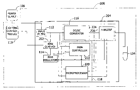
[0016] Referring to FIG. 2, a ballast 204 includes a bias control circuit 202
for energizing
a bias regulator 114 (e.g., a bias regulator circuit) in response to receiving
a remote enable
signal from the lighting control module 110 according to one embodiment of the
invention.
A vehicle operated by an operator has a vehicle lighting system 208 including
the ballast 204,
a lamp 104 and the lighting control module 110. In operation, a power supply
108 provides a
continuous supply voltage to the lighting control module 110 and the ballast
204. An input
filter 112 of the ballast 204 receives the supply voltage provided by the
power supply 108 to
the ballast 204 and filters noise from the supply voltage. The input filter
112 continuously
provides the filtered supply voltage to the bias control circuit 202 and a
power stage 116 of
the ballast 204. Thus, the input filter 112, power stage 116, and bias control
circuit 202
continuously receive power from the vehicle power supply 108, independent of
whether the
ballast 204 is providing power to the lamp 104. In one embodiment, the supply
voltage is a
9-16 volt DC voltage, and the input filter 112 comprises a capacitive and
inductive network
for providing power to the bias control circuit 202 and to the power stage
116.
[0017] The vehicle lighting control module 110 receives an input and provides
a remote
enable signal to the bias control circuit 202 of the ballast 204 as a function
of the received
input. The input may be a sensor signal and/or input from the operator. For
example, in one
embodiment, the vehicle lighting control module 110 provides the remote enable
signal to the
ballast 204 if a signal from an ambient light sensor indicates a low light
condition, or if the
CA 02635502 2008-06-20
2007P05583US (OSR 9838)
operator turns a headlight switch of the vehicle to an on position. In one
embodiment, the
remote enable signal is a digital signal having two states and is continuously
provided to the
ballast 204. In an enable state, the remote enable signal is a 12 volts direct
current (DC)
voltage, and in a disable state, the remote enable signal is a 0 volts DC
voltage. It is
contemplated that in other embodiments of the invention, the enable state may
be 0 volts DC
while the disable state is 12 volts DC if the bias control circuit 202 is
configured accordingly.
Additionally, the lighting control module l 10 may be a high power switch, a
low power
switch, or implemented in an integrated circuit.
[0018] The bias control circuit 202 energizes a bias regulator 114 (e.g., a
bias regulator
circuit) in response to receiving the remote enable signal from the lighting
control module
110. When energized, the bias regulator 114 generates a first bias voltage and
a second bias
voltage from the filtered supply voltage provided by the input filter 112. The
first bias
voltage (e.g., 8.5 volts DC) energizes a controller 118 of the ballast, and
the second bias
voltage (e.g., 12 volts DC) enables the power stage 116. The controller 118
controls the
power stage 116 to provide power from the power supply 108 to the lamp 104. In
one
embodiment, the power stage 116 supplies the lamp 104 with a square wave 500
Hertz
nominal signal at about 35 watts of power, and the lamp 104 is a type D3 metal
halide lamp.
In another embodiment of the invention, the bias regulator 114 generates a
bias voltage that
energizes both the controller 118 and enables the power stagc 116.
[0019] The power stage 116 comprises a DC to DC converter 224 and an H bridge
226.
The DC to DC converter 224 receives the filtered supply voltage from the input
filter 112 and
provides a stepped up DC voltage to the H bridge 226 in accordance with a
control signal
from the controller 118. In operation, the DC to DC converter 224 only
provides the stepped
up DC voltage to the H bridge 226 when the bias regulator 114 is energized by
the bias
control circuit 202 (i.e., when the ballast 204 is providing power to the lamp
104). The
control signal dictates the voltage of the stepped up DC voltage provided to
the H Bridge 226
by the DC to DC converter 224. The H bridge 226 switches the stepped up DC
voltage
provided by the DC to DC converter 224 in accordance with a reference
frequency provided
by the controller 118. Thus, the H bridge 226 provides the lamp 104 with a
relatively high
voltage square wave alternating current power signal.
[0020] The controller 118 comprises a microprocessor 220 and a pulse width
modulation
(PWM) controller 222. The microprocessor 220 and PWM controller 222 cooperate
to sense
the voltage and current provided by the input filter 112 and the voltage and
current of the
stepped-up DC voltage provided to the H bridge 226 by the DC to DC converter
224. Based
CA 02635502 2008-06-20
6 2007P05583US
(OSR 9838)
on these sensed inputs, the PWM controller 222 adjusts the control signal
provided to the DC
to DC converter 224 in order to adjust the voltage of the waveform supplied to
the lamp 104
and the microprocessor 220 adjusts the reference frequency provided to the H
bridge 226 in
order to adjust the frequency of the waveform provided to the lamp 104. In
steady-state
operation, the waveform provided to the lamp 104 is a square wave 40-90 volt
AC signal at
500 hertz nominal. One skilled in the art will recognize that the frequency
and voltage of the
waveform will vary in order to control the amount of power provided to the
lamp 104 and to
achieve striking and warm-up of the lamp 104.
[0021] Referring to FIG. 3, one embodiment of the bias control circuit 202 is
shown. In
the illustrated embodiment, the bias control circuit 202 receives a drain
voltage Vim from a
switching transistor of the DC to DC converter 224 in addition to the supply
voltage VsuppLy
via the input filter 112. When the supply voltage VSUPPLY is low, diode D15
and capacitor
C5 cooperate to provide a voltage higher than VSUPPLY (i.e., the drain voltage
VDS) to a
buffer circuit 302 of the bias control circuit 202 such that the bias control
circuit 202 operates
properly. The buffer circuit 302 receives the remote enable signal at jumper
310 from the
lighting control module 110 and selectively enables a first switch 304 and a
second switch
306. That is, when the remote enable signal is in the enable state, the buffer
circuit 302
enables the first switch 304 and the second switch 306 to conduct electricity,
and when the
remote enable signal is in the disable state, the buffer circuit 302 disables
the first switch 304
and the second switch 306 such that the first switch 304 and the second switch
306 do not
conduct electricity. The first switch 304 has a high side 312 connected to the
supply voltage
VSUPPLY from the input filter 112, an input 314 connected to the buffer
circuit 302, and a lovv
side 316 connected to a first portion of the bias regulator 114 which
generates the first bias
voltage when receiving electricity from the first switch 304. An output from
the bias control
circuit 202 to the first portion of the bias regulator is shown at Vcc. The
second switch 306
has a high side 322 connected to the rectified drain voltage \rips from the
switching transistor
of the DC to DC converter 224, an input 324 connected to the buffer circuit
302, and a low
side 326 connected to a second portion of the bias regulator 114 which
generates the second
bias voltage when receiving electricity from the second switch 306. An output
from the bias
control circuit 202 to the second portion of the bias regulator is shown at
VOUT.
[0022] In one embodiment of the invention, the controller 118, when receiving
the first
bias voltage (e.g., 8.5 volts DC), provides the first bias voltage to bias
voltage to the PWM
controller 222 and regulates the first bias voltage down to a third voltage
(e.g., 5 volts DC)
for the microprocessor 220. The first bias voltage is also used by the
controller 118 to drive a
CA 02635502 2008-06-20
7 2007P05583US
(OSR 9838)
gate of the switching transistor of the DC to DC converter 224. The second
bias voltage is
provided to the Fl drive of the power stage. The bias control circuit 202 is
also configured
such that the second bias voltage (e.g., 12 volts DC) back-feeds the first
bias voltage (e.g., 8.5
volts DC) when the first bias voltage droops by a predetermined amount. This
may be
accomplished, for example, by connecting a zener diode between the bias
control circuit 202
outputs Vcc and Vow- in the appropriate orientation as known by those skilled
in the art.
[0023] An input resistance of the buffer circuit 302 and the voltage of the
remote enable
signal determine a source current capacity required of the lighting control
module 110 to
enable the bias control circuit 202. In the embodiment shown in FIG. 3, the
total resistance
of input resistors R103, R15, and R104 is 8.8kOhms which means that the source
current
capacity for a 12 volt remote enable signal is less than 1.25 milliamperes.
The relatively low
source current requirement on the lighting control module 110 means that any
type of lighting
control module 110 may be used to generate the remote enable signal including
a direct
digital output from an integrated circuit (e.g., an electronic control module
of the vehicle).
[0024] In operation, when the remote enable signal is in the disable state,
the bias control
circuit 202 draws a current substantially equal to zero amperes. Resistors R94
and R97
provide a resistive pathway from the low side 316 of the first switch 304 to
ground and from
the input 314 of the first switch 304 to ground. These resistive pathways
prevent charge
accumulation at the input 314 and low side 316 of the first switch 304, which
prevents the
first switch 304 from conducting electricity when the remote enable signal is
in the disable
state. Similarly, resistors R96 and R95 provide a resistive pathway from the
low side 326 of
the second switch 306 to ground and from the input 324 of the second switch
306 to ground.
These resistive pathways prevent charge accumulation at the input 324 and low
side 326 of
the second switch 306, which prevents the second switch 306 from conducting
electricity
when the remote enable signal is in the disable state. Thus, the bias control
circuit 202 draws
a minimal current when the remote enable signal is in the disable state,
allowing the ballast
204 to be continuously connected to the power supply 108, eliminating the need
for a high
power capacity device to selectively connect the ballast 204 to the power
supply 108 such as
relay 106 as shown in prior art FIG. 1.
[0025] In one embodiment of the invention, the first switch 304 and the second
switch 306
are dual bipolar transistors, and the second portion of the bias regulator 114
is a capacitive
network for reducing transients at the output VouT of the second switch 306.
In another
embodiment of the invention, the second portion of the bias regulator 114 is
an integrated
circuit regulator. One skilled in the art will recognize that the first and
second switches
CA 02635502 2008-06-20
8 2007P05583US
(OSR 9838)
304,306 may be any type of switch, and that the first portion and second
portion of the bias
regulator 114 may be any type of regulators. For example, the first and second
switches may
be mosFETs, and the second portion of the bias regulator 114 may be an
integrated circuit
regulator while the first portion of the bias regulator 114 is a capacitive
network.
Additionally, other embodiments of the bias control circuit 202 may receive
only the supply
voltage, or may receive voltages from sources within the vehicle lighting
system other than
the drain of the switching transistor in the DC to DC converter 224.
[0026] Referring to FIG. 4, a method for selectively providing power to a lamp
from a
power supply as a function of a remote enable signal is illustrated. The
method starts at 402
with a power supply providing a supply voltage. At 404, a remote enable signal
in an enable
state is received at a bias control circuit, and at 406, the bias control
circuit energizes a bias
regulator. At 408, the bias regulator generates a first bias voltage and a
second bias voltage.
The first bias voltage is received at a controller at 410, and the second bias
voltage is received
at a power stage along with the supply voltage at 412. At 414, the controller
controls the
power stage to provide power to a lamp.
[0027] The order of execution or performance of the operations in embodiments
of the
invention illustrated and described herein is not essential, unless otherwise
specified. That is,
the operations may be performed in any order, unless otherwise specified, and
embodiments
of the invention may include additional or fewer operations than those
disclosed herein. For
example, it is contemplated that executing or performing a particular
operation before,
contemporaneously with, or after another operation is within the scope of
aspects of the
invention.
[0028] Embodiments of the invention may be implemented with computer-
executable
instructions. The computer-executable instructions may be organized into one
or more
computer-executable components or modules. Aspects of the invention may be
implemented
with any number and organization of such components or modules. For example,
aspects of
the invention are not limited to the specific computer-executable instructions
or the specific
components or modules illustrated in the figures and described herein. Other
embodiments of
the invention may include different computer-executable instructions or
components having
more or less functionality than illustrated and described herein.
[0029] When introducing elements of aspects of the invention or the
embodiments thereof,
the articles "a," "an," "the," and "said" are intended to mean that there are
one or more of the
elements. The terms "comprising," "including," and "having" are intended to be
inclusive
and mean that there may be additional elements other than the listed elements.
CA 02635502 2008-06-20
9 2007P05583US
(OSR 9838)
[0030] Having described aspects of the invention in detail, it will be
apparent that
modifications and variations are possible without departing from the scope of
aspects of the
invention as defined in the appended claims. As various changes could be made
in the above
constructions, products, and methods without departing from the scope of
aspects of the
invention, it is intended that all matter contained in the above description
and shown in the
accompanying drawings shall be interpreted as illustrative and not in a
limiting sense.