Note : Les descriptions sont présentées dans la langue officielle dans laquelle elles ont été soumises.
CA 02637956 2008-07-22
WO 2007/087598
PCT/US2007/061044
. . ....... _ _ _ .
A DEVICE AND METHOD FOR ADJUSTING THE PRESSURE BETWEEN A
FLOOR CLEANING IMPLEMENT AND A FLOOR
BACKGROUND OF THE INVENTION
[0001] The present invention relates to a device for adjusting the
pressure between a floor
cleaning implement of a floor cleaning machine and a floor. The floor cleaning
machine can
be one of many types of floor cleaning and treating machines, such as
scrubbers, sweepers,
and the like.. These types of machines can be used for the cleaning of hard
surfaces of large
floor areas in hotels, factories, office buildings, shopping centers and the
like.
[0002] In general such machines comprise a movable body supported by a
pair of drive
wheels and one or more caster wheels. With a scrubber, the body carries a
scrubbing device,
reservoirs for storing fresh and spent cleaning liquid, a device for dosing
fresh cleaning liquid
onto the floor, and a squeegee/vacuum pickup system for recovering spent
cleaning liquid
from the floor.
[00031 The scrubbing device normally comprises one or more brushes or
scrubbing pads,
a motor for driving the brushes, and a device for lifting the brushes off the
floor when large
areas are traversed without any cleaning action being required.
[0004] A typical conventional floor cleaning machine has the problem
in that a force for
pressing the pad against the floor-surface is changed during operation, due to
various causes
such as wear of the pad, reduced voltage of the batteries, state of the floor-
surface, and the
like, and as a result, the quality level of the polishing job for the floor-
surface is changed. If
the pad pressure is too strong, there is a possibility that the wax applied to
the floor-surface
comes off and the floor-surface may be scratched. In contrast, if the pad
pressure is too
weak, a sufficient polishing effect can not be obtained.
[0005] Conventional devices regulate brush/pad pressure many different
ways. For
example, some devices monitor the current within the scrubbing motors to
determine the
brush pressure and adjust the brush pressure actuating the lifting device for
the scrubbing
assembly.
[0006] The present invention has been designed to overcome some of the
complications
and/or problems inherent in the conventional devices.
1
CA 02637956 2008-07-22
WO 2007/087598
PCT/US2007/061044
SUMMARY OF THE INVENTION
[0007] The present invention relates to a cleaning implement pressure
regulating system
for a floor cleaning machine:
[0008] One particular embodiment of the present invention provides a
floor cleaning
machine comprising a motor-driven movable body carrying a cleaning implement
assembly
which comprises a housing having one or more cleaning implements coupled to
the housing.
A motor is coupled to the housing and the cleaning implements for driving the
cleaning
implements. An actuator, such as linear motor, is coupled to the housing for
lifting and =
lowering the housing. An elastically deformable cantilevered arm is coupled to
the body and
the actuator. A sensor is coupled to the cantilevered arm to sense or measure
deformation of
the cantilevered arm. A controller is coupled to the sensor and the actuator.
The controller
actuates the actuator in response to signals from the sensor indicating
deformation of the
cantilevered arm. Actuation of the actuator adjusts the pressure of th e
cleaning implern.' ents
against a floor.
[0009] Another embodiment is directed toward a device for regulating the
pressure
between a floor cleaning implement and a floor, wherein the floor cleaning
implement is
coupled to a floor cleaning machine. The device comprises a cantilevered arm
coupled to the
floor cleaning machine and a sensor coupled to the cantilevered arm and
positioned to sense
deflection or other deformation of the cantilevered arm. An actuator is
coupled between the
cantilevered arm and cleaning implements. The actuator is also coupled to the
sensor and
adapted to receive signals from the sensor to cause actuation of the actuator.
When pressure
other than a predetermined amount between the floor cleaning implement and the
floor
causes the cantilevered arm to deform, the sensor senses this deformation and
cause the
actuator to actuate in a direction that allows the cantilevered arm to return
to a position in
which the pressure is within the predetermined amount. In some embodiments,
the allowable
predetermined pressure is a range of pressures.
[0010] Another embodiment is directed toward a device for regulating
the pressure
between a floor cleaning implement and a floor, wherein the floor cleaning
implement is
coupled to a floor cleaning machine. The device includes a flexible
cantilevered ann coupled
between to the frame of the floor cleaning machine and the floor cleaning
implements. The
flexible cantilevered arm is adapted to elastically deform when the pressure
between the floor
2 =
CA 02637956 2013-06-28
=
=
cleaning implement and the floor is other than a predetermined amount. This
deformation of
the cantilevered arm returns the pressure between the floor cleaning
implements and the floor
to the predetermined amount.
[0011] A yet further embodiment pertains to a method for regulating the
pressure between a
floor cleaning implement and a floor, wherein the floor cleaning implement is
coupled to a
floor cleaning machine. The method comprises providing a cantilevered arm
coupled to the
floor cleaning machine and a sensor coupled to the cantilevered arm and
positioned to sense
deflection or other deformation of the cantilevered arm, providing an actuator
coupled to and
extending between the cantilevered arm and cleaning implement, the actuator
being coupled to
the sensor and adapted to receive signals from the sensor to cause actuation
of the actuator,
operating the floor cleaning machine, sensing deformation of the cantilevered
arm greater than
a predetermined amount, and actuating the actuator in a direction that allows
the cantilevered
arm to return to a position in which the deformation of the cantilevered arm
is less than the
predetermined amount.
[0012] Further aspects of the present invention, together with the
organization and operation
thereof, will become apparent from the following detailed description of the
invention when
taken in conjunction with the accompanying drawings.
BRIEF DESCRIPTION OF THE DRAWINGS
[0013] FIG. 1 is a perspective view of a floor scrubbing machine embodying
aspects of the
present invention.
[0014] FIG. 2 in a schematic representation of a presence regulation device
embodying
aspects of the present invention.
[00151 FIG. 3 is perspective view of a cantilevered arm incorporated in one
embodiment of
the present invention.
3
CA 02637956 2013-06-28
=
=
[0016] FIG. 4 is a perspective view of the cantilevered arm shown in FIG. 3,
wherein the
cantilevered arm is coupled to the frame of a floor cleaning machine and an
actuator is
coupled to the cantilevered arm.
[00171 FIG. 5 is another perspective view of the cantilevered arm shown in
FIG. 3,
wherein the cantilevered arm is coupled to the frame of a floor cleaning
machine and an
actuator is coupled to the cantilevered arm.
[0018] FIG. 6 is another perspective view of the cantilevered arm shown in
FIG. 3, with
this figure showing the sensor coupled to the cantilevered arm.
[0019] FIG. 7 is another perspective view of the cantilevered arm shown in
FIG. 3, with
this figure showing the sensor coupled to the cantilevered arm.
[00201 FIG. 8 is a perspective view of the actuator shown in FIGs. 4-7 coupled
to the
housing of a scrubbing assembly.
3a
CA 02637956 2008-07-22
WO 2007/087598
PCT/US2007/061044
[0021]
DETAILED DESCRIPTION
[0022] Before any embodiments of the invention are explained in
detail, it is to be
understood that the invention is not limited in its application to the details
of construction and
the arrangement of components set forth in the following description or
illustrated in the
. = following drawings. The invention is capable of other embodiments and
of being practiced
. . = or of being carried out in various ways. Also, it is to be understood
that the phraseology and
= terminology used herein is for the purpose of description and should not
be regarded as .
:limited: The use of "including," "comprising," or "having" and variations
thereof herein is
= meant to encompass the items listed thereafter and equivalents thereof as
well as additional
= items. The terms "mounted," "connected," and "coupled" are used broadly
and encompass
both direct and indirect mounting, connecting and coupling. Further,
"connected" and
"coupled" are not restricted to physical or mechanical connections or
couplings, and can
include electrical connections or couplings, whether direct or indirect.
Finally, as described
in subsequent paragraphs, the specific mechanical configurations illustrated
in the drawings
are intended to exemplify embodiments of the invention. Accordingly, other
alternative
mechanical configurations are possible, and fall within the spirit and scope
of the present
invention.
[0023] Referring now to FIG. 1, a floor cleaning machine 10 is shown,
comprising a
housing 11, an operator control assembly 12, a scrubbing assembly 13 and a
squeegee 14.
The cleaning machine 10 is supported on main drive wheels 16 and one or more
caster
wheels 18. Although it is not illustrated, several items such as a tank,
batteries, pumps,
motors, and other parts can be housed within the housing 11.
[0024] Although one particular embodiment of the invention will be
described in
connection with a scrubber, it should be clear that the invention has
application to other types
of floor maintenance vehicles, such as sweepers and the like. Accordingly, the
present
invention should not be limited to a scrubber.
[0025] The scrubbing assembly 13 includes a head or housing 20 having
one or more
cleaning implements 22, such as rotating, orbiting, or reciprocating brushes
or pads. A motor
24 is coupled to the housing 20 and the cleaning implements 22 to drive the
cleaning
implements 22 in a cleaning motion.
4
CA 02637956 2008-07-22
WO 2007/087598
PCT/US2007/061044
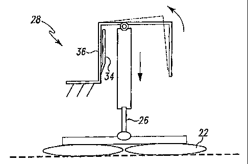
[0026] An actuator 26 is also coupled to the housing 20th lift and
lower the heusing 20
. and cleaning implements 22 relative to the floor. In the illustrated
embodiment, a linear
motor is used as the actuator 26. HoWever, in other embodiments, other
actuators 26 can be
used, such as a motor having a rack and pinion gear assembly and the like. The
actuator 26
. = :5 can be used to lift the housing.20 and implements entirely off of
the floor. Further; the
= actuator 26 can be used to place the implements 22 on the .floor and
adjust the pressure of the
=
=
= : implements 22 on the floor. =- =
=
. .
.10027] 'The actuator 26 is coubled to a Cantilevered arm 28, which
is coupled to the body,
frame, or housing of the floor cleaning machine '10. As illustrated, the
'cantilevered. arm 28
has two ends. One end is coupled to the frathe of the floor cleaning machine
10. The other
end is cantilevered. In the illustrated embodiment, the cantilevered arm 28 is
configured in a
substantially C-shaped configuration. However, in other embodiments, the
cantilevered arm
28 can have other configurations, such as more linear configurations, L-shaped
configurations, and the like. Other devices, other than the actuator or linear
motor can be
coupled to the cantilevered arm 28, which can affect the shape of the
cantilevered arm 28.
[0028] Due to the connection of the cantilevered arm 28 to the
scrubbing assembly 13,
increased pressure or force between the cleaning implements 22 and the floor
(caused by
imperfections in the floor for example) will cause a force to be applied to
the cantilevered
arm 28 via the actuator 26 extending between the cantilevered arm 28 and the
scrubbing
assembly 13. This force applied to the cantilevered arm 28 will cause the
cantilevered arm
28 to bend or deform elastically. This elastic deformation can help to reduce
undesirable
levels of pressure between the cleaning implements 22 and the floor caused
suddenly by
iniperfections in the floor. Once the imperfection is no longer in contact
with the cleaning
implements 22 (due to translation of the cleaning machine over the floor), the
cantilevered
aim 28 can return to a non-deflected or non-deformed condition (or to a normal
deflection
condition) due to elastic forces. As such, the originally desired pressure
between the cleaning
implements 22 and the floor can. be restored.
[0029] In some situations, however, the change in pressure between
the cleaning
implements 22 and the floor may not be a temporary condition. In such
situations, a sensor
30 that is coupled to the cantilevered arm 28 can sense or measure the
deformation of the
cantilevered arm 28 and cause the actuator 26 to actuate to change the
pressure to the desired
pressure, which can be a range of pressures. The sensor 30 can be any variety
of
5
CA 02637956 2008-07-22
WO 2007/087598
PCT/US2007/061044
=
deflection/deformation sensors. For example, a strain gauge can be used to
measure or sense
. the deformation of the cantilevered arrn, as well as Hall-effect
sensors, load sensors, optical
. sensors, ultrasOnic sensors, laser sensors, inductive sensors, capacitive
sensors', and the like.
=
. . In some embodiments, contact switches such as microswitches
and the.like zambe- used:as =
.5 = . we11. In such an embodiment, sufficient deformation-can cause the.
aim to: contact a switch. -
[0030] Intheillustrated embodiment, a hall-sensor is shown coupled to
the cantilevered
arm 28. :Specifically, as shown, one portion of the sensor 30 is coupled to a
portion 34 of the
= :cantileVered win 28 that is generally not Stressed, strained; or
otherWise deformed by forced
. . applied-to the cantilevered end of the arm during normaLoperation.
sedondbortion 36 of
= 10 the sensor 30 is coupled to a portion of the cantilevered arm 28:that
is deformed:by forced'
= : =. applied to the cantilevered end of the arm during operation.
Accordingly, forces applied to
. the cantilevered arm during operation, will cause relative, movement between
the two
= . portions of the sensor 30. As such, the forces applied to the
cantilevered arm 28 can. be
determined. =
= 15 [0031] In some embodiments, the sensor 30 is in communication
with a controller 32, and
the controller 32 is coupled to the actuator 26. Accordingly, the controller
32 can actuate the
actuator 26 in response to signals from the sensor indicating deformation of
the cantilevered.
arm 28. This actuation of the actuator 26 adjusts the pressure of the cleaning
implements 22
against the floor.
20 [00321 In operation, the actuator 26 can be used to raise and lower
the scrubbing or
cleaning assembly 13 relative to the floor. For example, when the floor
cleaning machine 10
is being transported from one cleaning location to another, the actuator 26
can be actuated to
lift the cleaning assembly 13 off of the floor. Once the cleaning assembly 13
reaches a
desired location, the actuator 26 can be actuated again to lower the cleaning
asse-inbly13 into
25 contact with the floor. Furthermore, the actuator 26 can continue to
actuate to place the
cleaning assembly 13 into proper contact with floor. In other words, the
actuator 26 can
place the cleaning assembly 13 into the desired pressure with the floor.
[0033] During operation, the scrubbing assembly 13 may contact
imperfections or other
variations in the floor surface, These imperfections or variations may cause a
sudden
30 increase in pressure between the cleaning implements 22 and the floor.
As previously
discussed, such sudden increases in pressure can cause damage to the floor if
not promptly
6
CA 02637956 2008-07-22
WO 2007/087598
PCT/US2007/061044
addressed. In some situations, the sudden increase in pressure is relieved by
the deformation
of the cantilevered arm 28. This situation may occur when the imperfection is
small and
quickly passed over by the floor cleaning machine. In such a situation, the
cantilevered arm
28 would return to the non-defleeted condition and the correct pressure would
be achieved
.once the imperfection is passed. . . .
[00341 In other situations, the imperfection may be so great, large, or
prolonged that
= elastic deformation of the cantilevered arm 28 may not be sufficient to
relieve the pressure.
In such situations, the sensor 30 on the cantilevered arm 28 mould sense the
deflection of the = =
cantilevered arm 28 and cause the actuator 26 to actuate, and thus, reduce the
pressure. = =.
[0035] In some situations, the change in pressure may be caused by wear and
tear on the
=
cleaning implements 22. In such situations, the cantilevered arm 28 may deform
in the
=
opposite direction due the pressure between the cleaning implements 22 and the
floor being
too low. Accordingly, the sensor 30 would sense a deflection or deformation of
the arm 28
and cause the actuator 2610 actuate in a direction that would increase the
pressure. The
sensor 30 would sense when the pressure is correct and stop the actuator 26
from actuating.
The sensor 30 would sense such a condition when the cantilevered arm 28 is
stressed,
deformed, or deflected a predetermined amount associated with the proper
pressure or force.
[0036] The embodiments described above and illustrated in the figures
are presented by
way of example only and are not intended as a limitation upon the concepts and
principles of
the present invention. As such, it will be appreciated by one having ordinary
skill in the art
that various changes in the elements and their configuration and. arrangement
are possible
without departing from. the spirit and scope of the present invention. For
example, various
alternatives to the certain features and elements of the present invention are
described with
reference to specific embodiments of the present invention. With the exception
of features,
elements, and manners of operation that are mutually exclusive of or are
inconsistent with
each embodiment described above, it should be noted that the alternative
features, elements,
and manners of operation described with reference to one particular embodiment
are
applicable to the other embodiments.
10031 Various features of the invention are set forth in the following
claims.