Note : Les descriptions sont présentées dans la langue officielle dans laquelle elles ont été soumises.
CA 02638059 2008-07-17
Thermocouple Head Unit
The present invention is concerned with thermocouple units.
In particular, it is concerned with the mounting terminal head
of a thermocouple unit.
Thermocouples typically comprise two wires of different metals
joined at their ends to form a loop. A temperature difference
between the joined ends causes a current to flow around the
loop, or a potential difference to be created. The difference
in temperature between the two ends (the hot and cold ends)
can be determined by measuring the potential difference (or
electromotive force - emf) set up when the circuit is open.
If the temperature of the cold end is known, one can then
determine the temperature of the hot end (or vice versa).
A thermocouple unit consists of one, two or more thermocouple
elements. A thermocouple element may be mineral insulated and
protected by a metal sheath. The measuring end of the
thermocouple element is placed in the location which
temperature is to be measured (e.g. a gas stream in a gas
turbine), while the other end is placed in a thermocouple head
with the non-measuring (typically cold) ends of the wires
connected to a measuring circuit. When two or more elements
are used, they are normally connected in parallel to provide
average temperature measurements. The elements' wires are
connected together inside the thermocouple head and then
connected to two output terminals made from the same material
as the wires. Several thermocouple units can be connected
together using a harness connected to the unit terminals.
The thermocouple head has to fulfil the following functions:
- to protect fragile thermocouple wires
- to house additional components such as ballast resistors
- to provide mounting for the thermocouple unit.
- to provide connection to the harness using terminals
1
CA 02638059 2015-08-11
As discussed above, the loop is typically enclosed within a
protective tube or sheath. The sensing (typically hot) end
of the loop is placed in the location where temperature is to
be measured (e.g. a gas stream in an aircraft engine or a gas
turbine). The other remote or measuring end of the loop is
held within a thermocouple head unit which includes means for
connecting the wire ends to measuring circuitry. Typically
the head is mounted on the outside of the element enclosing
the location which temperature is being measured or monitored
(e.g. the outside of the casing of an aero engine or gas
turbine).
Known thermocouple heads are made from metal. The known
thermocouple heads typically include a high number of
separate parts and their production or manufacture is multi-
operation with vacuum brazing and TIG (Tungsten Inert Gas)
welding. They are therefore relatively difficult and
expensive to make.
In an embodiment, there is provided a thermocouple head unit
for connecting a thermocouple to measurement or monitoring
apparatus or circuits, comprising: a metal casing for an end
of a thermocouple wire; the casing including a mounting
portion for mounting onto a surface to support the
thermocouple head unit, and having a port or ports for
receiving one or more thermocouple signal terminal elements
one or more conductive thermocouple signal terminals having a
portion passing through the port or ports, the signal
terminals each having a first portion within the casing for
connection to a thermocouple wire and a second
2
CA 02638059 2015-08-11
portion, outside the casing and electrically connected to the
first portion, for connection to the measurement or mounting
apparatus or circuits; the thermocouple head unit further
including an insulating support member for supporting the
thermocouple signal terminal or terminals in or through the
port or ports in the casing, the insulating support member
extending around an outside circumference of the metal casing
and including a port or ports through which a portion of the
thermocouple signal terminal or terminals passes.
In another embodiment, there is provided a thermocouple head
unit for connecting a thermocouple to measurement or
monitoring apparatus or circuits, comprising: a metal casing
for an end of a thermocouple wire; the casing including a
mounting portion for mounting onto a surface to support the
thermocouple head unit, and having two ports, each port being
for receiving one thermocouple signal terminal element one or
more conductive thermocouple signal terminals having a
portion passing through the respective port, the signal
terminals each having a first portion within the casing for
connection to a thermocouple wire and a second portion,
outside the casing and electrically connected to the first
portion, for connection to the measurement or mounting
apparatus or circuits; the thermocouple head unit further
including a ceramic insulating support member for supporting
the thermocouple signal terminal or terminals in or through
the respective port in the casing, the insulating support
member extending around the outside circumference of the
metal casing and including two ports through which a portion
of the thermocouple signal terminal or terminals passes, each
insulating support member port supporting one thermocouple
signal terminal element.
3
CA 02638059 2015-08-11
A preferred embodiment will be described, by way of example
only, with reference to the attached figures. The figures
and accompanying description are only for the purposes of
illustrating one or more preferred embodiments of the
invention and are not to be construed as unifying the
invention, limiting the invention or limiting the appending
claims. The skilled man will readily and easily envisage
alternative embodiments of the invention.
In the figures:
Figure 1 is a diagram illustrating a system for monitoring
temperature using a thermocouple having a pair of
thermocouple elements;
Figure 2 is a perspective view of an end of a known
thermocouple head;
Figure 3 is a cross-sectional illustration of the
thermocouple head unit construction of figure 2;
3a
CA 02638059 2008-07-17
Figure 4 is an illustration of a detail of the head unit of
figures 2 and 3;
Figure 5 is a perspective view of an end of a thermocouple
head unit embodying the invention;
Figure 6 is a cross-sectional illustration of the thermocouple
head unit of figure 5; and
Figure 7 is an illustration of a detail of the thermocouple
head unit of figures 5 and 6.
Referring to figure 1, this shows in schematic form a
thermocouple unit 1 having two thermocouple elements 2 of, for
example, type K.
In use, a pair of thermocouple elements is housed in a probe
12. The probe 12 is mounted, for example, in an aero engine
or gas turbine such that the tip 13 constitutes a hot junction
located inside the gas stream in the engine or turbine to
measure the gas temperature in the engine or turbine. For an
aero engine the temperature might typically be of the order of
8002C to 12002C.
At the other end, the thermocouple wires terminate in a head 1
mounted on the exterior of the, e.g., aero engine or gas
turbine. For an aero engine, the outside is typically at a
much lower temperature (of the order of 3002C to 6002C) to the
inside.
The thermocouple wires 14 are connected to thermocouple
terminals 4 in the thermocouple head 1. Wires 15 are
connected to the terminals to connect the thermocouple wires
to measuring circuitry 7. The measuring circuitry determines
the temperature difference between the tip 13 and the cold
junctions of the thermocouple from the voltage or potential
difference between the thermocouple wires. The measuring
circuitry has a temperature sensor to determine the
temperature of the cold junction and can therefore determine
the temperature of the hot junction or tip 13.
4
CA 02638059 2008-07-17
A number of thermocouple units may be connected in parallel in
the manner described in GB 2,344,892.
The known thermocouple heads (see figures 2 and 3) comprise a
metal (e.g. stainless steel) body or housing 2 welded to a
metal (e.g. stainless steel) flange 3. The thermocouple
signal terminals 4 are vacuum brazed metal/ceramic assemblies
welded into ports on the metal body 2. The ceramic components
8 surrounding the terminal assemblies 4 insulate the
respective terminals from the body (earth).
The vacuum brazed signal terminal subassemblies for providing
connections to wires and hence to the analytical circuitry are
located and TIG welded into ports in the head 1. The terminal
connection bushes are each insulated from the metal
thermocouple head body using a ceramic collar 8.
As shown in figure 4, the known ceramic insulators or collars
8 have two metallised areas 10 which are brazed to the metal
body 2 and to the respective terminal 4. The insulating
ceramic collars are small and therefore the insulating parts
between the two metallised parts 10 (which form part of the
brazed points) is short and subject to easy contamination
resulting in low insulation resistance and failure of the
thermocouple. This is a potentially serious problem in at
least aero engines where contamination can be caught in the
cavity 11 between the ceramic collar 8 and the metal body 2.
The insulating parts cannot be made longer in the known design
illustrated in figures 2 to 4 because that would require much
longer ceramic insulators. The ceramic insulators cannot
simply be made longer because that would increase the overall
size of the thermocouple head unit. The head unit cannot be
increased in size without also changing the dimensions of the
mounting harness. This is not possible in at least aero
engines which the mounting dimension is fixed for a give space
CA 02638059 2008-07-17
envelope of the engine. Furthermore simply lengthening the
ceramic insulators whiles leaving the rest of the head unit
unchanged would weaken the unit and make it more prone to
failure when subjected to high levels of vibration.
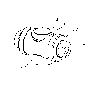
A thermocouple head embodying the present invention is shown
in figures 5 to 7. Where appropriate, the same reference
numerals to those of figures 2 to 4, are used to denote the
equivalent elements. The head unit of figures 5 to 7 has a
cylindrical metal (made from a low thermal expansion
coefficient alloy such as the chrome-iron NILO K (trade mark)
(Kovar) alloy so as to reduce differential expansion of
housing and ceramic components) lower housing or casing
portion 16 including a flange portion 3 for fixing onto a
surface (e.g. the outside of a turbine casing). The bottom of
the housing includes holes 17 through which two'sets of
mineral insulated thermocouple wires 14 comprising
thermocouples pass. A tubular metal upper housing portion 18
is welded to the lower housing portion 16 and includes two
holes or ports each for receiving an end of a metal
thermocouple terminal 4. A single ceramic insulating element
8 is brazed to supporting projections 19 on the metal upper
housing 18. The ceramic insulating element 8 supports the
thermocouple terminal units 4. A metal ferrule 20 is brazed
to the ceramic insulating unit 8 and welded to a respective
terminal 4.
The top or end of upper housing portion 18 is sealed by a
removable end cap 21.
The ceramic insulating element 8 is made from a ceramic
suitable for high temperature operation such as high purity
Alumina or Alumina and Zirconia.
The terminals 4 are made from the same material as the
thermocouple wires 14 to which they are joined. For a type K
thermocouple element (K and ic"), one terminal is made from e.g.
6
CA 02638059 2008-07-17
AlumelTM (Alumel is a metal based alloy containing about 5 per
cent Aluminium - Alumel is a trade mark of Concept Alloys LLC)
and has the AlumelTM wire(s) connected thereto while the other
is made from, e.g. ChromelTM and has the Chromel " (Chromel is a
nickel-based alloy containing about 10% chromium - Chromel is
a trade mark of Concept Alloys LLC) wire(s) connected,
thereto. The ferrule 20 is made the same material as the
terminals 4.
A portion 10 of the ceramic element 8 is metallised using, for
example, the well known molybdenum manganese process. The
ferrule 20 is then brazed to this metallised portion 10 and
welded to the terminal 4. The ferrule 20 is flexible to
accommodate different thermal expansion of the metal and
ceramic elements of the unit.
As discussed above the conductive materials which make up the
two thermocouple wires (e.g. Chromel and Alumel) are each used
to make terminals 4. Each terminal is one half of a
male/female connection. A terminal 4 could be in the form of a
bolt or a threaded socket (hole). For bolt terminals a harness
is attached using nuts, for socket terminals a harness is
attached using bolts. In the embodiment of figure 5, the
terminals 4 are female and are capable of receiving male
(bolt) connectors. In an alternative embodiment, they could
be male and for insertion into female connectors.
A protective sheath surrounds the different wires 14 of a K-
type thermocouple element 6. The wires of the thermocouple
element 6 pass through the surface on which the head 1 is
mounted and finish at the sensing tip 13 (not shown in figure
5) at the location which temperature is being monitored. The
wires of the two thermocouple elements are connected in
parallel to respective thermocouple terminals 4.
The head design of figures 5 to 7 uses one large ceramic
insulation block 8 serving two terminals 4. The ceramic part
7
CA 02638059 2008-07-17
has a much longer and exposed insulation path than the known
design illustrated in figures 2 to 4 and is easily accessible
from outside enabling its cleaning and therefore reducing the
risk of contamination and low insulation resistance. At the
same time the space envelope is not changed. The second
benefit of the design is increased mechanical strength of the
ceramic block offering higher tightening torque for the
attaching mating harness. A higher tightening torque helps
ensure that the mounting harness to which the head is
connected will not become detached from the head as a result
of vibrations.
8